Using the other interior features
Other interior features
|
|
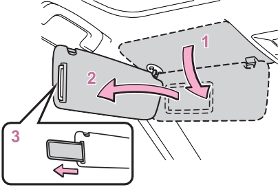
Slide the cover to open.
The light turns on when the cover is opened.
If the vanity lights remain on when
the engine switch is turned to OFF, the lights will go off automatically after 20 minutes.
|
|
|
To prevent battery discharge
Do not leave the vanity lights on for extended periods while the engine is off. |
 NOTICE
|
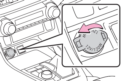
Power outlet |
12 V: Accessories that run on less than 10 A.
120 VAC: Accessories that use less than 100 W.
’ Front Open the lid.
|
|
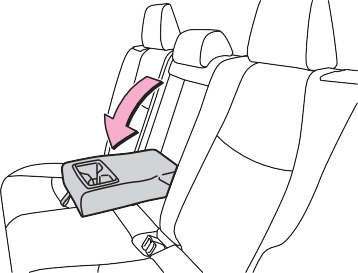
’ Console box (if equipped)
Open the console box and open the lid.
’ Luggage compartment (if equipped)
Open the lid.
Open the lid.
’ 12 V
The engine switch is in ACC or ON.
’ 120 VAC
The engine switch is in ON.
Disconnect electrical devices with charging functions, such as mobile battery packs.
If such devices are left connected, the engine switch may not be turned off normally.
|
|
|
120 VAC
Do not use a 120 VAC appliance that requires more than 100 W. If a 120 VAC appliance that con- sumes more than 100 W is used, the protection circuit will cut the power supply. To prevent battery discharge
Do not use the power outlet lon- ger than necessary when the engine is not running. Appliances that may not operate properly (120 VAC)
The following 120 VAC appliances may not operate properly even if their power consumption is under 100 W. Appliances with high initial peak wattage
Measuring devices that pro- cess precise data
Other appliances that require an extremely stable power supply
|
 NOTICE
The USB charging ports are for charging only. They are not designed for data transfer or other purposes.
Depending on the external device, it may not charge prop- erly. Refer to the manual included with the device before using a USB charging port.
’ Console box
Open the console box and open the lid.
’ Rear Open the lid.
|
|
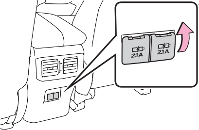
The engine switch is in ACC or ON.
cle has been parked in the sun
Depending on the connected exter- nal device, charging may occasion- ally be suspended and then start again. This is not a malfunction.
|
Wireless charger (if equipped) |
This function cannot be used with portable devices that are larger than the charging area. Also, depending on the portable device, it may not operate as normal. Please read the opera- tion manual for portable devices to be used.
The “Qi” symbol is a trademark of the Wireless Power Consor- tium.
Power supply switch Operation indicator light Charge area
Switches on and off with each press of the power supply switch.
When turned on, the operation indi- cator light (green) comes on.
Even with the engine off, the on/off state of the power supply switch is memorized.
When charging, the operation indi-
cator light (orange) comes on.
If charging is not occurring, try plac- ing the portable device as close to the center of the charging area as possible.
When charging is complete, the operation indicator light (green) comes on.
|
Operation indicator light |
Conditions |
|
Turning off |
When the Wireless charger power supply is off |
|
Green (comes on) |
On Standby (charging possible state) |
|
When charging is com- plete* |
*: Depending on the portable device, there are cases where the operation indicator light will con- tinue being lit up orange even after the charging is complete.
When an error occurs, the oper- ation indicator light flashes an orange color.
Handle the error based on the following tables.
|
Suspected causes |
Handling method |
|
Vehicle to char- ger communica- tion failure. |
Contact your Toyota dealer. |
|
Suspected causes |
Handling method |
|
Temperature ris- ing within the wireless charger. |
Stop charging at once and start charging again after for a while. |
The engine switch is in ACC or ON.
Qi standard wireless charge stan- dard can be used on compatible devices.
However, not all Qi standard devices and compatibility are guar- anteed.
Starting with mobile phones and smartphones, it is aimed for low power electrically supplied portable devices of no more than 5W.
Do not charge in situations where cover and accessories not able to handle Qi are attached to the porta- ble device. Depending on the type of cover and accessory, it may not be possible to charge. When charging is not performed even with the portable device placed on the charge area, remove the cover and accessories.
Turn off the wireless charger and confirm that the noise has decreased. If the noise decreases, continuously pushing the power supply switch of the wireless char- ger for 2 seconds, the frequency of the charger can be changed and the noise can be reduced.Also, on that occasion, the operation indicator light will flash orange 2 times.
When a portable device gets warm while charging, charging may stop due to the protection function on the portable device side. In this case, when the tem- perature of the portable device drops significantly, charge again.
When the power supply is turned on, while searching for the portable device a sound will be produced, however this is not a malfunction.
|
|
|
|
|
To prevent damage to the armrest
Do not apply too much load on the armrest. |
 NOTICE
|
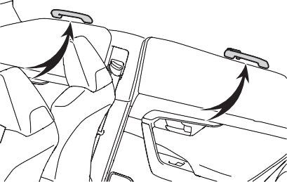
Assist grips |
An assist grip installed on the ceiling can be used to support your body while sitting on the seat.
|
|

*: If equipped
|
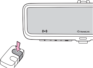
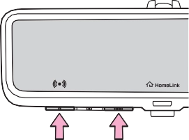
System components |
’ Vehicles with auto anti-glare inside rear view mirror
HomeLink® indicator light
Garage door operation indi- cators
HomeLink® icon
Illuminates while HomeLink® is
operating.
’ Vehicles with Digital Rear- view Mirror
HomeLink® logo
Appears while HomeLink® is oper- ating.
When the menu/enter button (P.147) is pressed, the logo dis-
appears even while the HomeLink® is operating.
HomeLink® indicator light
Illuminates above each button selected.
’ For vehicles sold in the U.S. mainland, Hawaii, Guam, Saipan, American Samoa and Puerto Rico
 ’ For vehicles sold in Canada
Visit on the web at www.home- link.com/toyota or call 1-800-355- 3515.
|
|
|
When programming a garage door or other remote control device
The garage door or other device may operate, so ensure people and objects are out of danger to prevent potential harm. Conforming to federal safety standards
Do not use the HomeLink® com- patible transceiver with any garage door opener or device that lacks safety stop and reverse fea- tures as required by federal safety standards. This includes any garage door that cannot detect an interfering object. A door or device without these features increases the risk of death or serious injury. |
 WARNING
|
When operating or program- ming HomeLink®
Never allow a child to operate or play with the HomeLink® buttons. |
|
Programming HomeLink® |
Steps 1 through 3 must be per- formed within 60 seconds, oth- erwise the HomeLink® indicator light will stop flashing and pro- gramming will not be success- fully completed.
Keep the HomeLink® indicator light in view while programming.
|
|
’ Programming a device other than an entry gate (for U.S.A. owners)
Press and hold the remote con- trol transmitter button until the HomeLink® indicator light changes from slowly flashing orange to rapidly flashing green (rolling code) or continuously lit green (fixed code), then release the button.
’ Programming an entry gate (for U.S.A. owners)/Program- ming a device in the Cana- dian market
Press and release the remote control transmitter button at 2 second intervals, repeatedly, until the HomeLink® indicator light changes from slowly flash- ing orange to rapidly flashing (green) (rolling code) or continu- ously lit (green) (fixed code).
Two or more people may be needed to complete rolling code programming.
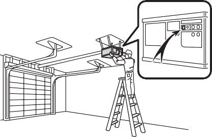
1 Locate the “Learn” or “Smart” button on the garage door opener motor in the garage.
This button can usually be found where the hanging antenna wire is attached to the unit. The name and color of the button may vary by manufacturer. Refer to the owner’s manual supplied with the garage
door opener motor for details.
|
|
Perform 3 within 30 seconds after
performing 2.
If the garage door opener motor operates when the HomeLink® button is pressed, the garage door opener motor recognizes the HomeLink® signal.
When enabled, 2-way communi- cation allows you to check the status of the opening and clos- ing of a garage door through indicators in your vehicle.
2-way communication is only available if the garage door opener motor used is a compati- ble device. (To check device compatibility, refer to www.homelink.com.)
1 Within 5 seconds after pro- gramming the garage door opener has been completed, if the garage door opener motor is trained to Home- Link®, both garage door operation indicators will flash rapidly (green) and the light on the garage door opener motor will blink twice, indicat- ing that 2-way communica- tion is enabled.
If the indicators do not flash, per-
form 2 and 3 within the first 10
pleted.
When the following procedure is performed, buttons which already have devices registered to them can be overwritten:
®
presses of the HomeLink® button after programming has been com-
The status of the opening and closing of a garage door is shown by the garage door oper- ation indicators.
’ Vehicles with auto anti-glare inside rear view mirror
Opening Closing
’ Vehicles with Digital Rear- view Mirror
Opening Closing
This function is only available if the
garage door opener motor used is a compatible device. (To check device compatibility, refer to www.homelink.com.)
|
Color |
Status |
|
Orange (flash- ing) |
Currently open- ing/closing |
|
Green |
Opening/closing has completed |
|
Red (flashing) |
Feedback sig- nals cannot be received |
 To recall the previous door oper- ation status, press and release either HomeLink® buttons
 and
and  or
or  and (vehicles with auto anti-glare inside rear
view mirror), and
or and (vehicles with Digital Rear-view Mirror) simultaneously. The last recorded status will be dis- played for 3 seconds.
|
Erasing the entire Home- Link® memory (all three codes) |
Press and hold the 2 outside buttons for 10 seconds until the HomeLink® indicator light changes from continuously lit (orange) to rapidly flashing (green).
If you sell your vehicle, be sure to erase the programs stored in the HomeLink® memory.
|
|
Maintenance and care 7
.................................. 556
Wiper insert replacement
.................................. 591
Wireless remote con- trol/electronic key battery
.................................. 594
Checking and replacing fuses 597
Light bulbs 599
549
7
Download Manual