Refueling
|
Before refueling the vehi- cle |
P.669
To help prevent incorrect fueling, your vehicle has a fuel tank opening that only accommodates the spe- cial nozzle on unleaded fuel pumps.
The malfunction indicator lamp may illuminate erroneously if refueling is performed repeatedly when the fuel tank is nearly full.
222 4-4. Refueling
|
|
|
When refueling
Observe the following precautions to prevent fuel overflowing from the fuel tank: Securely insert the fuel nozzle into the fuel filler neck.
Stop filling the tank after the fuel nozzle automatically clicks off.
Do not top off the fuel tank.
|
 WARNING
|
|
|
Refueling
Do not spill fuel during refueling. Doing so may damage the vehi- cle, such as causing the emission control system to operate abnor- mally or damaging fuel system components or the vehicle’s painted surface. |
 NOTICE
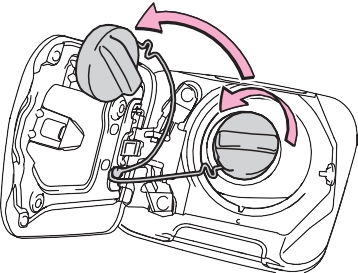
2 Turn the fuel tank cap slowly to open it and put it into the holder on the fuel filler door.
|
|
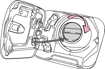
After refueling, turn the fuel tank cap until you hear a click. Once the cap is released, it will turn slightly in the opposite direction.
|
|
The fuel tank cap may be unfas- tened or loose. Turn the engine switch off, check the cap and tighten it securely. If the message remains, wait a few seconds and then turn the engine switch off once again.
|
|
|
When replacing the fuel tank cap
Do not use anything but a genu- ine Toyota fuel tank cap designed for your vehicle. Doing so may cause a fire or other incident which may result in death or seri- ous injury. |
 WARNING
|
Driving assist system |
P.238
P.212
P.249
P.251
|
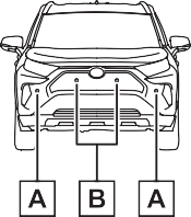
Sensors |
Two types of sensors, located behind the front grille and wind- shield, detect information neces- sary to operate the drive assist systems.
|
|
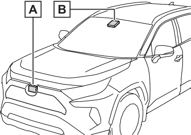
Radar sensor Front camera
Observe the following precau- tions.
Otherwise, the radar sensor may not operate properly, possibly leading to an accident resulting in death or serious injury.
If the front of the radar sensor or the front or back of the grille cover is dirty or covered with water droplets, snow, etc., clean it.
Clean the radar sensor and grille cover with a soft cloth to avoid damaging them.
If the radar sensor, front grille, or front bumper has been sub- jected to a strong impact, have the vehicle inspected by your Toyota dealer.
’ For vehicles sold in the U.S.A., Hawaii, American Samoa, Guam, Saipan and Puerto Rico
’ For vehicles sold in Canada
A system may be temporarily unavailable or there may be a mal- function in the system.
If the message does not disappear, contact your Toyota dealer.
|
Situation |
Actions |
|
To clean the part |
|
|
When the area |
of the wind- |
|
around a sensor |
shield in front of |
|
is covered with |
the front camera, |
|
dirt, moisture |
use the wind- |
|
(fogged up, cov- |
shield wipers or |
|
ered with con- |
the windshield |
|
densation, ice, |
defogger of the |
|
etc.), or other |
air conditioning |
|
foreign matter |
system (P.505, |
|
512). |
If the message does not disappear, contact your Toyota dealer.
|
Detectable objects |
|
System functions |
When the system determines that the possibility of a frontal collision is high, a buzzer will sound and a warning message will be displayed on the multi- information display to urge the driver to take evasive action.
When the system determines that the possibility of a frontal collision is high, the system applies greater braking force in relation to how strongly the brake pedal is depressed.
If the system determines that the possibility of a frontal colli- sion is extremely high, the brakes are automatically applied to help avoid the collision or reduce the impact of the colli- sion.
enabled/disabled on the  screen (P.94) of the multi- information display.
The system is automatically enabled each time the engine switch is turned to ON.
The pre-collision warning timing
can be changed on the  screen (P.94) of the multi- information display.
The warning timing setting is retained when the engine switch is turned to OFF. However, if the pre- collision system is disabled and re- enabled, the operation timing will return to the default setting (mid- dle).
|
|
This is the default setting.
The pre-collision system is enabled and the system determines that the pos- sibility of a frontal collision with a detected object is high.
Each function is operational at the following speed
|
Detectable objects |
Vehicle speed |
Relative speed between your vehicle and object |
|
Vehicles |
Approx. 7 to 110 mph (10 to 180 km/h) |
Approx. 7 to 110 mph (10 to 180 km/h) |
|
Bicyclists and pedestri- ans |
Approx. 7 to 50 mph (10 to 80 km/h) |
Approx. 7 to 50 mph (10 to 80 km/h) |
|
Detectable objects |
Vehicle speed |
Relative speed between your vehicle and object |
|
Vehicles |
Approx. 20 to 110 mph (30 to 180 km/h) |
Approx. 20 to 110 mph (30 to 180 km/h) |
|
Bicyclists and pedestri- ans |
Approx. 20 to 50 mph (30 to 80 km/h) |
Approx. 20 to 50 mph (30 to 80 km/h) |
|
Detectable objects |
Vehicle speed |
Relative speed between your vehicle and object |
|
Vehicles |
Approx. 7 to 110 mph (10 to 180 km/h) |
Approx. 7 to 110 mph (10 to 180 km/h) |
|
Bicyclists and pedestri- ans |
Approx. 7 to 50 mph (10 to 80 km/h) |
Approx. 7 to 50 mph (10 to 80 km/h) |
The system may not operate in the following situations:
The system detects objects based on their size, profile, motion, etc. However, an object may not be detected depending on the sur- rounding brightness and the motion, posture, and angle of the detected object, preventing the system from operating properly. (P.236)
The illustration shows an image of detectable objects.
braking
If either of the following occur while
the pre-collision braking function is operating, it will be canceled:
in front of your vehicle that may be mistaken for a detectable object
smoke
pressure, etc.)

|
Functions included in LTA system |
from its lane or course*, a warn- ing is displayed on the multi- information display, and a warn- ing buzzer will sound to alert the driver.
When the warning buzzer sounds, check the area around your vehicle and carefully operate the steering wheel to move the vehicle back to the center of the lane.
Vehicles with Blind Spot Monitor: When the system determines that the vehicle might depart from its lane and that the possibility of a col- lision with an overtaking vehicle in the adjacent lane is high, the lane departure alert will operate even if the turn signals are operating.
*: Boundary between asphalt and the side of the road, such as grass, soil, or a curb
from its lane or course*, the sys- tem provides assistance as nec- essary by operating the steering wheel in small amounts for a short period of time to keep the vehicle in its lane.
If the system detects that the steer- ing wheel has not been operated for a fixed amount of time or the steering wheel is not being firmly gripped, a warning is displayed on the multi-information display and the function is temporarily can- celed.
Vehicles with Blind Spot Monitor: When the system determines that the vehicle might depart from its lane and that the possibility of a col- lision with an overtaking vehicle in the adjacent lane is high, the steer- ing assist function will operate even if the turn signals are operating.
*: Boundary between asphalt and the side of the road, such as grass, soil, or a curb
This function is linked with dynamic radar cruise control with full-speed range and pro- vides the required assistance by operating the steering wheel to keep the vehicle in its current lane.
When dynamic radar cruise control with full-speed range is not operat- ing, the lane centering function does not operate.
In situations where the white (yel- low) lane lines are difficult to see or are not visible, such as when in a traffic jam, this function will operate to help follow a preceding vehicle by monitoring the position of the preceding vehicle.
If the system detects that the steer- ing wheel has not been operated for a fixed amount of time or the steering wheel is not being firmly gripped, a warning is displayed on
the multi-information display and the function is temporarily can- celed.
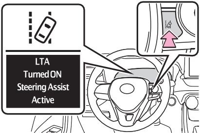
The LTA indicator illuminates and a message is displayed on the multi- information display.
When the LTA system is turned on or off, operation of the LTA system continues in the same condition the next time the engine is started.
|
|
|
Indications on multi-infor- mation display |
The illumination condition of the indicator informs the driver of the system operation status.
Illuminated in white: LTA system is operating.
Illuminated in green: Steering wheel assistance of the steering assist function or lane centering function is operating.
Flashing in orange: Lane departure alert function is operating.
Displayed when the multi-informa- tion display is switched to the driv- ing support system information display.
Indicates that steering wheel assis- tance of the steering assist function
or lane centering function is operat- ing.
Both outer sides of the lane are dis- played: Indicates that steering wheel assist of the lane centering function is operating.
One outer side of the lane is dis- played: Indicates that steering wheel assist of the steering assist function is operating.
Both outer sides of the lane are flashing: Alerts the driver that their input is necessary to stay in the center of the lane (lane centering function).
Displayed when the multi-informa- tion display is switched to the driv- ing support system information display.
Indicates that steering assist of the lane centering function is operating by monitoring the position of a pre- ceding vehicle.
When the follow-up cruising display is displayed, if the preceding vehi- cle moves, your vehicle may move in the same way. Always pay care- ful attention to your surroundings and operate the steering wheel as necessary to correct the path of the vehicle and ensure safety.
Displayed when the multi-informa- tion display is switched to the driv-
|
|
Indicates that the system is recog- nizing white (yellow) lines or a course*. When the vehicle departs from its lane, the white line dis- played on the side the vehicle departs from flashes orange.
|
|
Indicates that the system is not able to recognize white (yellow) lines or a course* or is temporarily can- celed.
*: Boundary between asphalt and the side of the road, such as grass, soil, or a curb
ing support system information
display.
lane lines or a course*2. (When a white [yellow] line or course*2 is recognized on only one side, the system will operate only for the recognized side.)
*1: The function operates even if the vehicle speed is less than approximately 32 mph (50 km/h) when the lane centering function is operating.
*2: Boundary between asphalt and the side of the road, such as grass, soil, or a curb
This function operates when all of the following conditions are met in addition to the operation conditions for the lane departure alert function.
screen of the multi-information display is set to “ON”. (P.89)
This function operates when all of the following conditions are met.
screen of the multi-information display is set to “ON”. (P.89)
This function operates when all of the following conditions are met.
“Lane Center” in the screen of the multi-information display are set to “ON”. (P.89)
*: Boundary between asphalt and the side of the road, such as grass, soil, or a curb
In the following situations, a warning message urging the driver to hold the steering wheel and the symbol shown in the illustration are dis- played on the multi-information dis- play to warn the driver. The warning stops when the system determines that the driver holds the steering wheel. Always keep your hands on the steering wheel when using this system, regardless of warnings.
If the driver continues to keep their hands off of the steering wheel, the buzzer sounds, the driver is warned and the function is temporarily can- celed. This warning also operates in the same way when the driver con- tinuously operates the steering wheel only a small amount.
Depending on the vehicle condition and road conditions, the warning may not operate. Also, if the system determines that the vehicle is driv- ing around a curve, warnings will occur earlier than during straight- lane driving.
steering wheel assist of the steer- ing assist function is operating.
If the driver continues to keep their hands off of the steering wheel and the steering wheel assist is operat- ing, the buzzer sounds and the driver is warned. Each time the buzzer sounds, the continuing time of the buzzer becomes longer.
When the system determines that the vehicle is swaying while the vehicle sway warning function is operating, a buzzer sounds and a warning message urging the driver to rest and the symbol shown in the illustration are simultaneously dis- played on the multi-information dis- play.
Depending on the vehicle and road conditions, the warning may not operate.
If the following warning message is displayed on the multi-information display and the LTA indicator illumi- nates in orange, follow the appropri- ate troubleshooting procedure. Also, if a different warning message is displayed, follow the instructions displayed on the screen.
The system may not be operating properly. Have the vehicle inspected by your Toyota dealer.
The system is temporarily canceled
due to a malfunction in a sensor other than the front camera. Turn the LTA system off, wait for a little while, and then turn the LTA system back on.
The function cannot be used as the vehicle speed exceeds the LTA operation range. Drive slower.
Function settings can be changed. (P.94)
*: If equipped
nizes a sign, the sign will be dis- played on the multi-information display.
If signs other than speed limit signs are recognized, they will be displayed in an overlapping stack under the current speed limit sign.
The following types of road signs are recognized.
A non-official or a recently intro- duced traffic sign may not be recog- nized.
 Speed limit
 Do Not Enter
 Stop
Stop
 Yield
Yield
Depending on the situation, traf- fic environment (traffic direction,
speed unit) may be detected incorrectly and a warning dis- play may not operate properly.
P.94
In the following situations, a dis- played speed limit sign will stop being displayed automatically:
In the following situations, do not enter, stop and yield signs will stop being displayed automatically:
In the following situations, RSA does not operate normally and may not recognize signs, display the incorrect sign, etc. However, this does not indicate a malfunction.
camera for a short amount of time.
If the engine switch was last turned to OFF while a speed limit sign was displayed on the multi-information display, the same sign displays again when the engine switch is turned to ON.
The system may be malfunctioning. Have the vehicle inspected by your Toyota dealer.
Some functions can be customized. (P.94)
|
System Components |
Indicators 
Vehicle-to-vehicle distance switch
“+RES” switch
Cruise control main switch Cancel switch
“-SET” switch
|
|
|
Before using dynamic radar cruise control with full-speed range
Driving safely is the sole responsibility of the driver. Do not rely solely on the system, and drive safely by always pay- ing careful attention to your sur- roundings.
|
 WARNING
|
When weather conditions are bad enough that they may pre- vent the sensors from detecting correctly (fog, snow, sand- storm, heavy rain, etc.)
When there is rain, snow, etc. on the front surface of the radar or front camera
In traffic conditions that require frequent repeated acceleration and deceleration
When your vehicle is towing a trailer or during emergency tow- ing
When an approach warning buzzer is heard often
|
When driving on downhill slopes, the vehicle-to-vehicle distance may become shorter.
When there are no vehicles ahead
The vehicle travels at the speed set by the driver.
When a vehicle is detected running ahead of you, the system automatically decelerates your vehicle. When a greater reduction in vehicle speed is nec- essary, the system applies the brakes (the stop lights will come on at this time). The system will respond to changes in the speed of the vehicle ahead in order to maintain the vehicle-to-vehicle distance set by the driver. Approach warning warns you when the system cannot decelerate suffi- ciently to prevent your vehicle from closing in on the vehicle ahead.
When the vehicle ahead of you stops, your vehicle will also stop (vehicle is stopped by system control). After the vehicle ahead starts off, pressing the “+RES” switch or depressing the accelerator pedal (start-off operation) will resume follow-up cruising. If the start-off operation is not performed, system control continues to keep your vehicle stopped.
When the turn signal lever is operated and your vehicle moves to a left lane while driving at 50 mph (80 km/h) or more, the vehicle will quickly acceler- ate to help to overtake a passing vehicle.
When there are no longer any preceding vehicles driving slower than the set speed
The system accelerates until the set speed is reached. The system then returns to constant speed cruising.
constant speed control mode. (P.258)
Dynamic radar cruise control indi- cator will come on and a message will be displayed on the multi-infor- mation display. Press the switch again to deactivate the cruise con- trol.
If the cruise control main switch is pressed and held for 1.5 seconds or more, the system turns on in
mately 20 mph [30 km/h]) and press the “-SET” switch to set the speed.
Cruise control “SET” indicator will come on.
The vehicle speed at the moment the switch is released becomes the set speed.
Fine adjustment: Press the switch. Large adjustment: Press and hold the switch to change the speed,
and release when the desired speed is reached.
’ For the U.S. mainland and Hawaii
Fine adjustment: By 1 mph (1.6 km/h)*1 or 1 km/h (0.6 mph)*2 each time the switch is pressed
Large adjustment: Increases or decreases in 1 mph (1.6 km/h)*1 or 1 km/h (0.6 mph)*2 increments for as long as the switch is held
Fine adjustment: By 1 mph (1.6 km/h)*1 or 1 km/h (0.6 mph)*2 each time the switch is pressed
Large adjustment: Increases or decreases in 5 mph (8 km/h)*1 or 5 km/h (3.1 mph)*2 increments for as long as the switch is held
Fine adjustment: By 1 mph (1.6 km/h)*1 or 1 km/h (0.6 mph)*2 each time the switch is pressed
Large adjustment: The speed will continue to change while the switch is held.
*1: When the set speed is shown in “MPH”
*2: When the set speed is shown in “km/h”
The vehicle-to-vehicle distance is set automatically to long mode when the engine switch is turned to ON.
If a vehicle is running ahead of you,
the preceding vehicle mark will also be displayed.
Vehicle-to-vehicle distance increases/decreases in accor-
dance with vehicle speed. When the vehicle is stopped by system control, the vehicle stops at a certain vehicle-to-vehicle dis- tance depending on the situa- tion.
|
Distance options |
Vehicle-to-vehi- cle distance |
|
Long |
Approximately 160 ft. (50 m) |
|
Medium |
Approximately 130 ft. (40 m) |
|
Short |
Approximately 100 ft. (30 m) |
|
Resuming follow-up cruising when the vehicle has been stopped by sys- tem control (vehicle-to- vehicle distance control mode) |
After the vehicle ahead of you starts off, press the “+RES” switch.
Your vehicle will also resume follow-up cruising if the acceler- ator pedal is depressed after the vehicle ahead of you starts off.
The speed control is also canceled when the brake pedal is depressed. (When the vehicle has been stopped by system control, depressing the brake pedal does not cancel the setting.)
When your vehicle is too close to a vehicle ahead, and suffi- cient automatic deceleration via the cruise control is not possi- ble, the display will flash and the buzzer will sound to alert the driver. An example of this would be if another driver cuts in front of you while you are following a vehicle. Depress the brake pedal to ensure an appropriate vehicle-to-vehicle distance.
In the following instances, warn- ings may not occur even when the vehicle-to-vehicle distance is small.
|
Selecting constant speed control mode |
When constant speed control mode is selected, your vehicle will maintain a set speed without controlling the vehicle-to-vehi- cle distance. Select this mode only when vehicle-to-vehicle dis- tance control mode does not function correctly due to a dirty radar, etc.
Immediately after the switch is pressed, the dynamic radar cruise control indicator will come on. After- wards, it switches to the cruise con- trol indicator.
Switching to constant speed control mode is only possible when operat- ing the switch with the cruise con- trol off.
Cruise control “SET” indicator will come on.
The vehicle speed at the moment the switch is released becomes the set speed.
Adjusting the speed setting:
P.256
Canceling and resuming the speed
setting: P.258
The vehicle can accelerate by oper- ating the accelerator pedal. After accelerating, the set speed resumes. However, during vehicle- to-vehicle distance control mode, the vehicle speed may decrease below the set speed in order to maintain the distance to the preced- ing vehicle.
Vehicle-to-vehicle distance control mode is automatically canceled in the following situations.
If vehicle-to-vehicle distance control mode is automatically canceled for any reasons other than the above, there may be a malfunction in the system. Contact your Toyota dealer.
Constant speed control mode is automatically canceled in the follow- ing situations:
A brake operation sound may be heard and the brake pedal response may change, but these are not mal- functions.
Warning messages and buzzers are used to indicate a system malfunc- tion or to inform the driver of the need for caution while driving. If a warning message is shown on the multi-information display, read the message and follow the instructions. (P.228, 633)
In the case of the following and depending on the conditions, oper- ate the brake pedal when decelera- tion of the system is insufficient or operate the accelerator pedal when acceleration is required.
As the sensor may not be able to correctly detect these types of vehi- cles, the approach warning (P.258) may not be activated.
In the case of the following condi- tions, operate the brake pedal (or accelerator pedal, depending on the situation) as necessary.
As the sensor may not be able to correctly detect vehicles ahead, the system may not operate properly.
*: If equipped
|
System components |
Turning the BSM function/RCTA function on/off.
cators
BSM function:
When a vehicle is detected in a blind spot of the outside rear view mirrors or approaching rapidly from behind into a blind spot, the outside rear view mirror indicator on the detected side will illuminate. If the turn signal lever is operated toward the detected side, the outside rear view mirror indicator will flash.
RCTA function:
When a vehicle approaching from the right or left at the rear of the vehicle is detected, both outside rear view mirror indicators will flash.
When the Blind Spot Monitor is enabled, the BSM indicator illumi- nates.
When the RCTA function is dis- abled, the RCTA OFF indicator illu- minates.
If a vehicle approaching from the right or left at the rear of the vehicle is detected, the RCTA icon (P.268) for the detected side will be displayed.
If a vehicle approaching from the right or left at the rear of the vehicle is detected, a buzzer will sound from behind the rear seat.
|
Turning the BSM func- tion/RCTA function on/off |
enabled/disabled on  screen of the multi-information display. (P.94)
In strong sunlight, the outside rear view mirror indicator may be difficult to see.
The RCTA buzzer may be difficult to hear over loud noises such as high audio volume.
The sensor voltage has become abnormal, or water, snow, mud, etc., may be built up in the vicinity of the sensor area of the rear bumper. (P.265)
Removing the water, snow, mud, etc., from the vicinity of the sensor area should return it to normal.
Also, the sensor may not function normally when used in extremely hot or cold weather.
There may be a sensor malfunction or misaligned. Have the vehicle inspected at a Toyota dealer.
Some functions can be customized. (P.94)
’ For vehicles sold in the U.S.A., Hawaii, American Samoa, Guam, Saipan and Puerto Rico
’ For vehicles sold in Canada
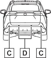
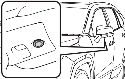
Blind Spot Monitor sensors are installed inside the left and right sides of the rear bumper respec- tively. Observe the following to ensure the Blind Spot Monitor can function correctly.
If a sensor or its surrounding area on the rear bumper is dirty or covered with snow, the Blind Spot Monitor may not operate and a warning message (P.263) will be displayed. In this situation, clear off the dirt or snow and drive the vehicle with the operation conditions of the BSM function (P.267) satis- fied for approximately 10 min- utes. If the warning message does not disappear, have the vehicle inspected by your Toy- ota dealer.
If a sensor is moved even slightly off position, the system may malfunction and vehicles may not be detected correctly. In the following situations, have your vehicle inspected by your Toyota dealer.
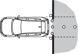
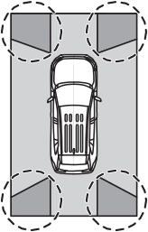
Vehicles that are traveling in areas that are not visible using the outside rear view mirrors (the blind spots)
Vehicles that are approaching rapidly from behind in areas that are not visible using the outside rear view mirrors (the blind spots)
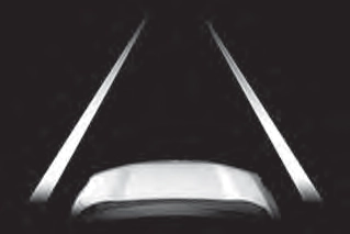
The areas that vehicles can be detected in are outlined below.
The range of each detection area is:
The area between the side of the vehicle and 1.6 ft. (0.5 m) from the side of the vehicle cannot be detected.
Approximately 9.8 ft. (3 m) to 197 ft. (60 m) from the rear bumper
The greater the difference in speed between your vehicle and the detected vehicle is, the farther away the vehicle will be detected, causing the outside rear view mirror indicator to illuminate or flash.
taken rapidly by your vehicle
The BSM function is operational when all of the following conditions are met:
The BSM function will detect a vehi- cle present in the detection area in the following situations:
The BSM function is not designed to detect the following types of vehi- cles and/or objects:
*: Depending on the conditions, detection of a vehicle and/or object may occur.
when driving on the edge of a lane, and the vehicle in an adja- cent lane is far away from your vehicle
|
The Rear Cross Traffic Alert function (if equipped) |
|
|
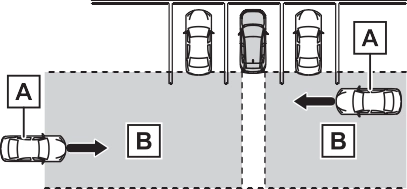
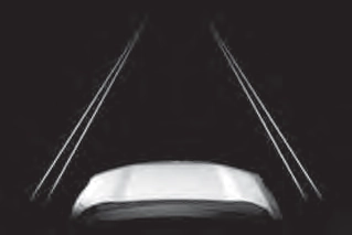
Approaching vehicles Detection areas
equipped)
When a vehicle approaching from the right or left at the rear of the vehicle is detected, the following will be displayed on the navigation system (if equipped) or multimedia sys- tem (if equipped) screen.
monitor (if equipped) is dis-
played
 : The RCTA function is mal- functioning (P.263)
The areas that vehicles can be detected in are outlined below.
The buzzer can alert the driver of faster vehicles approaching from farther away.
The RCTA function operates when all of the following conditions are met:
The buzzer volume can be adjusted on the multi-information display. (P.94)
The RCTA function is not designed to detect the following types of vehi- cles and/or objects.
*: Depending on conditions, detec- tion of a vehicle and/or object may occur.
*: If equipped
|
System components |
|
|
display)
When the sensors detect an object, such as a wall, a graphic
is shown on the multi-informa- tion display depending on the position and distance to the object.
Front corner sensor detection
Front center sensor detec- tion*1
Rear corner sensor detec- tion*2
Rear center sensor detec- tion*2
*1: Displayed when the shift lever is in a driving position
*2: Displayed when the shift lever is in R
A simplified image is displayed on the upper corner of the screen when an obstacle is detected.
’ Panoramic view*
A graphic is shown when the panoramic view monitor is dis- played.
*: A simplified image is displayed on the upper corner of the screen when an obstacle is detected while magnified display is shown.
A simplified image is displayed on the upper corner of the screen when an obstacle is detected.
|
Turning intuitive parking assist on/off |
The Intuitive parking assist can
be enabled/disabled on  screen of the multi-information display. (P.94)
When the intuitive parking assist function is disabled, the intuitive parking assist OFF indicator (P.79) illuminates on the multi- information display.
To re-enable the system, select  on the multi-information display,
select  and turn it on.
If the system is disabled, it will remain off even if the engine switch is turned to ON after the engine switch has been turned off.
|
|
|
Notes when washing the vehi- cle
Do not apply intensive bursts of water or steam to the sensor area. Doing so may result in the sensor malfunctioning. When using a high pressure washer to wash the vehicle, do not spray the sensors directly, as doing so may cause a sensor to malfunction.
When using steam to clean the vehicle, do not direct steam too close to the sensors as doing so may cause a sensor to malfunc- tion.
|
 WARNING
A sensor may be covered with ice, snow, dirt, etc. Remove the ice, snow, dirt, etc., from the sensor to return the system to normal.
Also, due to ice forming on a sensor at low temperatures, a warning message may be displayed or the sensor may not be able to detect an object. Once the ice melts, the sys- tem will return to normal.
If a warning message is displayed even if the sensor is clean, there may be a sensor malfunction. Have the vehicle inspected by your Toyota
dealer.
Certain vehicle conditions and the surrounding environment may affect the ability of a sensor to correctly detect objects. Particular instances where this may occur are listed below.
play may be displayed abnormally, or objects, such as a wall, may not be detected.
a sensor is extremely hot or cold.
The shape of the object may pre- vent the sensor from detecting it. Pay particular attention to the follow- ing objects:
People may not be detected if they are wearing certain types of cloth- ing.
This ISM device complies with Canadian ICES-001.
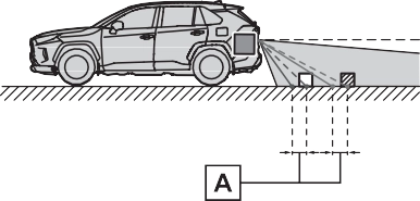
Approximately 4.9 ft. (150 cm)
Approximately 2.1 ft. (63 cm)
The diagram shows the detection range of the sensors. Note that the sensors cannot detect objects that are extremely close to the vehicle.
The range of the sensors may change depending on the shape of the object, etc.
The images may differ from that shown in the illustrations.
|
Multi-information display |
Navigation or multimedia system screen |
|
|
|
Multi-information display |
Navigation or multimedia system screen |
|
|
|
Multi-information display |
Navigation or multimedia system screen |
|
|
|
Multi-information display* |
Navigation or multimedia system screen |
|
|
*: The distance segments will blink slowly.
|
Multi-information display* |
Navigation or multimedia system screen |
|
|
*: The distance segments will blink rapidly.
When the vehicle comes within approximately 1.1 ft. (34 cm) of the object, the
buzzer sounds continuously.
However, if another object is detected or the situation changes while the buzzer is muted, the buzzer begins sounding again.
muted by pressing of the meter con-
trol switches while a suggestion that says mute is available is shown on the multi-information display.
Mute will be automatically canceled in the following situations.
The buzzer volume can be adjusted on the multi-information display. (P.94)
*: If equipped
|
PKSB (Parking Support Brake) system |
P.289
|
|
|
If “Parking Support Brake Unavailable” is displayed on the multi-information display and the PKSB OFF indicator is flashing
If this message is displayed immediately after the engine switch is changed to ON, operate the vehicle carefully, paying atten- tion to your surroundings. It may be necessary to drive the vehicle for a certain amount of time before the system returns to nor- mal. (If the system is not return to normal after driving for a while, clean the sensors and their sur- rounding area on the bumpers.) |
 NOTICE
|
Enabling/Disabling the Parking Support Brake |
 The Parking Support Brake can be enabled/disabled on
screen of the multi-information display. All of the Parking Sup- port Brake functions (static objects and rear-crossing vehi- cles) are enabled/disabled simultaneously. (P.94)
When the Parking Support Brake is disabled, the PKSB OFF indicator (P.79) illuminates on the multi- information display.
To re-enable the system, select  on the multi-information display,
select  and turn it on.
If the system is disabled, it will remain off even if the engine switch is turned to ON after the engine switch has been turned off.
Depending on the situation, engine output restriction control will oper- ate to either limit acceleration or restrict output as much as possible.
Acceleration greater than a certain amount is restricted by the system.
Navigation system (if equipped) or multimedia system (if equipped) screen: No warning displayed
Multi-information display: “Object Detected Acceleration Reduced”
PKSB OFF indicator: Not illumi- nated
Buzzer: Does not sound
The system has determined that stronger-than-normal brake opera- tion is necessary.
Navigation system (if equipped) or multimedia system (if equipped) screen: “BRAKE!”
Multi-information display: “BRAKE!”
PKSB OFF indicator: Not illumi- nated
Buzzer: Short beep
The system determined that emer- gency braking is necessary.
Navigation system (if equipped) or multimedia system (if equipped) screen: “BRAKE!”
Multi-information display: “BRAKE!”
PKSB OFF indicator: Not illumi- nated
Buzzer: Short beep
The vehicle has been stopped by brake control operation.
Navigation system (if equipped) or multimedia system (if equipped) screen: “Press Brake Pedal”
Multi-information display: “Switch to Brake” (If the accelerator pedal is not depressed, “Brake” will be dis- played.)
PKSB OFF indicator: Illuminated Buzzer: Short beep
restrain any increase in the vehicle speed. (Engine output restriction control: See figure 2.)
Additionally, if the accelerator pedal continues to be depressed, the brakes will be applied automatically to reduce the vehicle speed. (Brake control: See figure 3.)
Engine output Braking force Time
put restriction control oper- ates
Engine output Braking force Time
Engine output restriction con- trol begins operating (System
determines that possibility of collision with detected object is high)
Engine output Braking force Time
Engine output restriction con- trol begins operating (System determines that possibility of collision with detected object is high)
Brake control begins operat- ing (System determines that possibility of collision with detected object is extremely high)
If the vehicle is stopped due to oper- ation of the Parking Support Brake, the Parking Support Brake will be
disabled and the PKSB OFF indica- tor will illuminate. If the Parking Sup- port Brake operates unnecessarily, brake control can be canceled by depressing the brake pedal or wait- ing for approximately 2 seconds for it to automatically be canceled.
Then, the vehicle can be operated by depressing the accelerator pedal.
To re-enable the Parking Support Brake when it is disabled due to operation of the Parking Support Brake, either enable the system again (P.279), or turn the engine switch off and then back to ON. Additionally, if the object becomes no longer in the traveling direction of the vehicle or if the traveling direc- tion of the vehicle changes (such as changing from moving forward to backing up, or from backing up to moving forward), the system will be re-enabled automatically.
If the vehicle is stopped due to oper- ation of the Parking Support Brake, the Parking Support Brake will be disabled and the PKSB OFF indica- tor will illuminate.
ing over the sensor surface, such as in a heavy rain. When the sys- tem determines that it is normal, the system will return to normal.
If this message continues to be displayed even after initialization, have the vehicle inspected by your Toyota dealer.
The system needs to be initialized. To initialize the system, drive the vehicle straight ahead for 5 seconds or more at a speed of approximately 22 mph (35 km/h) or more.
*: If equipped
 When traveling at a low speed and the brake pedal is not depressed, or is depressed late
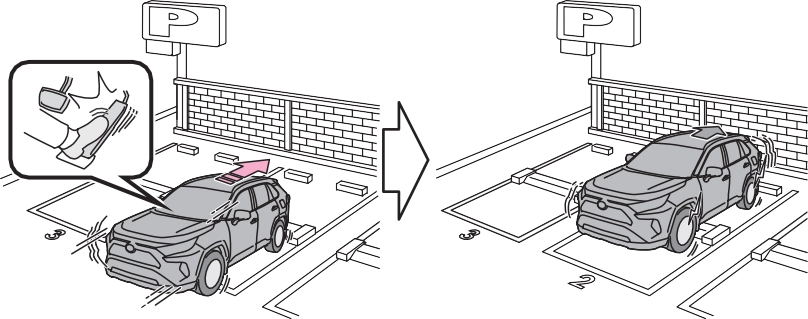 When the accelerator pedal is depressed excessively
|
Types of sensors |
P.271
The function will operate when the PKSB OFF indicator is not illumi- nated or flashing (P.77, 79) and all of the following conditions are met:
The function will stop operating if any of the following conditions are met:
brake control.
The detection range of the Parking Support Brake function (static objects) differs from the detection range of the intuitive parking assist. (P.276) Therefore, even if the intu- itive parking assist detects an object and provides a warning, the Parking Support Brake function (static objects) may not start operating.
The sensors may not be able to detect certain objects, such as the following:
Regardless of whether the intuitive parking assist system is enabled or not (P.273), if the Parking Support Brake function (static objects) is enabled (P.279), the front or rear sensors detect an object and brake
control and engine output restric- tion control are performed, the intui- tive parking assist buzzer will sound to notify the driver of the approxi- mate distance to the object.
In some situations, such as the fol- lowing, the Parking Support Brake function (static objects) may operate even though there is no possibility of a collision.
drainage ditches
been changed due to a collision or other impact
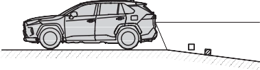
In some situations, such as the fol- lowing, this function may not oper- ate properly.
an incline, on gravel, or on grass.
*: If equipped
|
Types of sensors |
P.265
|
|
|
Do not modify, disassemble or paint the sensors.
Do not replace a rear radar sen- sor with a part other than a gen- uine part.
Do not damage the rear radar sensors, and always keep the radar sensors and their sur- rounding area on the bumper clean.
If the area around a rear radar sensor is subjected to an impact, the system may not operate properly due to a sen- sor malfunction. Have the vehi- cle inspected by your Toyota dealer.
Observe the rear radar sensor handling precautions. (P.265)
|
 WARNING
The function will operate when the PKSB OFF indicator is not illumi- nated or flashing (P.77, 79) and all of the following conditions are met:
The function will stop operating if any of the following conditions are met:
The detection area of the Parking Support Brake function (rear-cross- ing vehicles) differs from the detec- tion area of the RCTA function (P.269). Therefore, even if the RCTA function detects a vehicle and provides an alert, the Parking Sup- port Brake function (rear-crossing vehicles) may not start operating.
The Parking Support Brake function (rear-crossing vehicles) is not designed to detect the following
types of vehicles and/or objects:
*: Depending on the conditions, detection of a vehicle and/or object may occur.
In some situations such as the fol- lowing, the Parking Support Brake function (rear-crossing vehicles) may operate even though there is no possibility of a collision.
 When the parking space faces a street and vehicles are being driven on the street
In some situations, such as the fol- lowing, the radar sensors may not detect an object and this function may not operate properly
antenna is installed near a radar sensor
 When turning while backing up
*: If equipped
|
Driving precautions |
Pay attention to the following precautions when using the rear view monitor system.

|
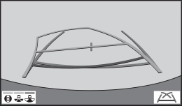
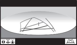
Screen description |
Vehicle width guide line
Displays a guide path when the vehicle is being backed straight up.
This line indicates the estimated vehicle center on the ground.
Shows distance behind the vehicle.
1.5 ft. (0.5 m) (red) from the edge of the bumper.
Shows distance behind the vehicle.
The rear view monitor system displays an image of the view from the bumper of the rear area of the vehicle.
Corners of bumper
monitor system is located as shown in the illustration.
If dirt or foreign matter (such as water droplets, snow, mud, etc.) is adhering to the camera, it cannot transmit a clear image. In this case, flush it with a large quantity of water and wipe the camera lens clean with a soft and wet cloth.
|
|
|
The rear view monitor system may not operate properly in the following cases.
If the back of the vehicle is hit, the position and mounting angle of the camera may change.
As the camera has a water proof construction, do not detach, disassemble or modify it. This may cause incorrect operation.
When cleaning the camera lens, flush the camera with a large quantity of water and wipe it with a soft and wet cloth. Strongly rubbing the camera lens may cause the camera lens to be scratched and unable to transmit a clear image.
Do not allow organic solvent, car wax, window cleaner or a glass coating to adhere to the camera. If this happens, wipe it off as soon as possible.
If the temperature changes rap- idly, such as when hot water is poured on the vehicle in cold weather, the system may not operate normally.
When washing the vehicle, do not apply intensive bursts of water to the camera or camera area. Doing so may result in the camera malfunctioning.
Do not expose the camera to strong impact as this could cause a malfunction. If this hap- pens, have the vehicle inspected by your Toyota dealer as soon as possible.
|
 NOTICE
may not actually be parallel with the dividing lines of the parking space, even when they appear to be so. Be sure to check visually.
The distance guide lines will appear to be closer to the vehi- cle than the actual distance.
Because of this, objects will appear to be farther away than they actually are. In the same way, there will be a margin of error between the fixed guide lines and the actual dis- tance/course on the road.
The distance guide lines will appear to be farther from the vehicle than the actual distance. Because of this, objects will appear to be closer than they actually are. In the same way, there will be a margin of error between the guide lines and the actual distance/course on the road.
When any part of the vehicle sags due to the number of pas- sengers or the distribution of the load, there is a margin of error between the fixed guide lines on the screen and the actual dis- tance/course on the road.
A margin of error
The distance guide lines are dis- played according to flat surfaced objects (such as the road). It is not possible to determine the position of three-dimensional objects (such as vehicles) using the vehicle width guide lines and distance guide lines. When approaching a three-dimen- sional object that extends out- ward (such as the flatbed of a truck), be careful of the follow- ing.
Visually check the surroundings and the area behind the vehicle. In the case shown below, the truck appears to be outside of the vehicle width guide lines and the vehicle does not look as if it hits the truck. However, the rear body of the truck may actually cross over the vehicle width guide lines. In reality if you back up as guided by the vehicle width guide lines, the vehicle may hit the truck.
up to point , you will hit the
Vehicle width guide lines
Visually check the surroundings and the area behind the vehicle. On the screen, it appears that a
truck is parking at point . However, in reality if you back
truck. On the screen, it appears
that is closest and is far- thest away. However, in reality,
the distance to and is the same, and is farther than and .
If you notice any of the following symptoms, refer to the likely cause and the solution, and re-check.
If the symptom is not resolved by the solution, have the vehicle inspected by your Toyota dealer.
|
Symptom |
Likely cause |
Solution |
|
The image is difficult to see |
The vehicle is in a dark area
The temperature around the lens is either high or low
The outside tempera-
ture is low There are water drop- lets on the camera
It is raining or humid
Foreign matter (mud etc.) is adhering to the camera
Sunlight or headlights
are shining directly into the camera The vehicle is under fluorescent lights, sodium lights, mer- cury lights etc.
|
Back up while visually checking the vehicle’s surroundings. (Use the monitor again once con- ditions have been improved.) The procedure for adjusting the picture quality of the rear view monitor system is the same as the procedure for adjusting the screen. (P.390) |
|
The image is blurry |
Dirt or foreign matter (such as water droplets, snow, mud etc.) is adhering to the camera. |
Flush the camera with a large quantity of water and wipe the camera lens clean with a soft and wet cloth. |
|
The image is out of alignment |
The camera or sur- rounding area has received a strong impact. |
Have the vehicle inspected by your Toy- ota dealer. |
|
The camera position is out of alignment. |
Have the vehicle inspected by your Toy- ota dealer. |
|
|
The fixed guide lines are very far out of alignment |
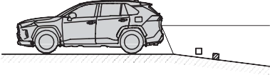
The vehicle is tilted (there is a heavy load on the vehicle, tire pressure is low due to a tire puncture, etc.)
The vehicle is used on an incline.
|
If this happens due to these causes, it does not indicate a malfunc- tion. |
|
Back up while visually checking the vehicle’s surroundings. |
*: If equipped
|
Driving precautions |
Pay attention to the following precautions when using the parking assist monitor.
The parking assist monitor screen will be displayed if the shift lever is shifted to the “R” while the engine switch is in ON.
Each time the display mode switching button is selected, the mode will change as follows:
’ Rear view
Displays the rear view of the vehi- cle.
Each time the button is selected, the rear view mode and the wide rear view mode are switched.
Select to switch the guide line mode. (P.303)
Estimated course line display mode
Parking assist guide line display mode Distance guide line display mode.
When a sensor detects a vehicle approaching from the rear, the direction of the vehicle approaching from the rear is displayed and the buzzer sounds.
When a sensor detects a stationary object, the direction of and the approximate distance to the a sta- tionary object are displayed and the buzzer sounds.
*: If equipped
Displays a near 180° image from the rear view camera.
Each time the button is selected, the rear view mode and the wide rear view mode are switched.
Select to switch the guide line mode. (P.303)
Estimated course line display mode
Parking assist guide line display mode Distance guide line display mode.
When a sensor detects a stationary object, the direction of stationary object is displayed and the buzzer sounds.
When a sensor detects an obstacle, the direction of and the approxi- mate distance to the obstacle are displayed and the buzzer sounds.
*: If equipped
|
Using the system |
Use any of the following modes.
|
|
’ Estimated course line display mode (P.304)
Estimated course lines are dis- played which move in accor- dance with the operation of the steering wheel.
’ Parking assist guide line dis- play mode (P.305)
The steering wheel return points (parking assist guide lines) are displayed.
This mode is recommended for
those who are comfortable with parking the vehicle without the aid of the estimated course lines.
’ Distance guide line display mode (P.306)
Distance guide lines only are displayed.
This mode is recommended for those who are comfortable with parking the vehicle without the aid of the guide lines.
|
Estimated course line dis- play mode |
’ Rear view
Vehicle width guide line
Displays a guide path when the vehicle is being backed straight up.
Show an estimated course when the steering wheel is turned.
Show distance behind the vehicle when the steering wheel is turned.
Shows distance behind the vehicle.
Indicates the estimated vehicle center on the ground.
Vehicle width guide line
Displays a guide path when the vehicle is being backed straight up.
Show an estimated course when the steering wheel is turned.
Show distance behind the vehicle when the steering wheel is turned.
Shows distance behind the vehicle.
1.5 ft. (0.5 m) (blue) from the edge of the bumper.
Indicates the estimated vehicle center on the ground.
|
|
|
If the steering wheel is straight and the vehicle width guide lines and the estimated course lines are not in alignment, have the vehicle inspected by your Toyota dealer.
|
 WARNING
|
Parking assist guide line display mode |
Vehicle width guide line
Displays a guide path when the vehicle is being backed straight up.
Show the path of the smallest turn possible behind the vehicle.
Shows distance behind the vehicle.
Indicates the estimated vehicle center on the ground.
Vehicle width guide line
Displays a guide path when the vehicle is being backed straight up.
Show the path of the smallest turn possible behind the vehicle.
Shows distance behind the vehicle.
Indicates the estimated vehicle center on the ground.
|
Distance guide line dis- play mode |
Distance guide lines
Shows distance behind the vehicle.
Distance guide lines
Shows distance behind the vehicle.
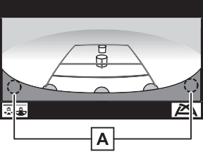
’ Rear view
Corners of bumper
The area around both corners of the bumper will not be displayed.
|
|
Corners of bumper
The area around both corners of the bumper will not be displayed.
If dirt or foreign matter (such as water droplets, snow, mud, etc.) is adhering to the camera, it cannot transmit a clear image. In this case, flush it with a large quantity of water and wipe the camera lens clean with a soft and wet cloth.
may not actually be parallel with the dividing lines of the parking space, even when they appear to be so. Be sure to check visually.
The distance guide lines will appear to be closer to the vehi- cle than the actual distance.
Because of this, objects will appear to be farther away than they actually are. In the same way, there will be a margin of error between the guidelines and the actual distance/course on the road.
The distance guide lines will appear to be farther from the vehicle than the actual distance. Because of this, objects will appear to be closer than they actually are. In the same way, there will be a margin of error between the guidelines and the actual distance/course on the road.
When any part of the vehicle sags due to the number of pas- sengers or the distribution of the load, there is a margin of error between the guide lines on the screen and the actual dis- tance/course on the road.
A margin of error
The estimated course lines tar- get flat surfaced objects (such as the road). It is not possible to determine the position of three- dimensional objects (such as vehicles) using the estimated course lines and distance guide lines. When approaching a three-dimensional object that extends outward (such as the flatbed of a truck), be careful of the following.
Visually check the surroundings and the area behind the vehicle. In the case shown below, the truck appears to be outside of the estimated course lines and the vehicle does not look as if it hits the truck. However, the rear body of the truck may actually cross over the estimated course lines. In reality if you back up as guided by the estimated course lines, the vehicle may hit the truck.
up to point , you will hit the
Estimated course lines
Visually check the surroundings and the area behind the vehicle. On the screen, it appears that a
truck is parking at point . However, in reality if you back
truck. On the screen, it appears
that is closest and is far- thest away. However, in reality,
the distance to and is the same, and is farther than and .
If you notice any of the following symptoms, refer to the likely cause and the solution, and re-check.
If the symptom is not resolved by the solution, have the vehicle inspected by your Toyota dealer.
|
Symptom |
Likely cause |
Solution |
|
The image is difficult to see |
The vehicle is in a dark area
The temperature around the lens is either high or low
The outside tempera-
ture is low There are water drop- lets on the camera
It is raining or humid
Foreign matter (mud etc.) is adhering to the camera
Sunlight or headlights
are shining directly into the camera The vehicle is under fluorescent lights, sodium lights, mer- cury lights etc.
|
Back up while visually checking the vehicle’s surroundings. (Use the monitor again once con- ditions have been improved.) The procedure for adjusting the picture quality of the parking assist monitor is the same as the procedure for adjusting the screen display. (P.390) |
|
The image is blurry |
Dirt or foreign matter (such as water droplets, snow, mud etc.) is adhering to the camera. |
Flush the camera with a large quantity of water and wipe the camera lens clean with a soft and wet cloth. |
|
The image is out of alignment |
The camera or sur- rounding area has received a strong impact. |
Have the vehicle inspected by your Toy- ota dealer. |
|
The camera position is out of alignment. |
Have the vehicle inspected by your Toy- ota dealer. |
|
|
The guide lines are very far out of align- ment |
The vehicle is tilted (there is a heavy load on the vehicle, tire pressure is low due to a tire puncture, etc.)
The vehicle is used on an incline.
|
If this happens due to these causes, it does not indicate a malfunc- tion. |
|
Back up while visually checking the vehicle’s surroundings. |
|
Symptom |
Likely cause |
Solution |
|
The estimated course lines move even though the steering wheel is straight |
There is a malfunction in the signals being output by the steering sensor. |
Have the vehicle inspected by your Toy- ota dealer. |
|
Close the back door. |
||
|
Guide lines are not dis- played |
The back door is open. |
If this does not resolve the symptom, have the vehicle inspected by your Toyota dealer. |
|
The estimated course lines are not displayed |
Battery has been rein- stalled.
The steering wheel has been moved while the battery was being reinstalled.
Battery power is low.
The steering sensor has been reinstalled.
There is a malfunction in the signals being output by the steering sensor.
|
Stop the vehicle, and turn the steering wheel as far as it will go to the left and right. If this does not resolve the symptom, have the vehicle inspected by your Toyota dealer. |
*: If equipped
may hit another vehicle or possi- bly cause an accident.
Pay attention to the following precautions when using the panoramic view monitor.
|
|
|
Never depend on the panoramic view monitor entirely. The image and the position of the guide lines displayed on the screen may differ from the actual state. Use caution just as you would when driving any other vehicle.
Always make sure to check all around the vehicle with your own eyes when driving.
Never drive while looking only at the screen as the image on the screen is different from actual conditions. If you are driving while looking only at the screen, you may hit a person or an object, resulting in an accident. When driving, be sure to check the vehicle’s surroundings with your own eyes and the vehicle’s mirrors.
Depending on the circum- stances of the vehicle (number of passengers, amount of lug- gage, etc.), the position of the guide lines displayed on the screen may change. Be sure to check visually around the vehi- cle before proceeding.
|
 WARNING
|
Display |
’ Moving view
’ Rear view & panoramic view
’ Wide front view & side views
’ Side views
’ Rear view & side views
When you press the camera switch or shift the shift lever to the “R” position while the engine switch is in ON, the panoramic view moni- tor operates.
The monitor displays various views of the position of the vehicle. (The following is an example)


Map screen, audio screen, etc. Moving view


 See-through view
Map screen, audio screen, etc. Wide front view & panoramic view Side views


 Rear view & panoramic view Wide rear view
 Rear view
The moving view screen and the see-through view screen pro- vide support when checking the areas of around the vehicle while parking. These screens display an image of the vicinity of the vehicle combined from the 4 cameras. The screen will dis- play a 360° view around the vehicle from either inside the vehicle or from a birds-eye view at an angle.
To display the moving view/see- through view screen, press the camera switch when the shift lever is in the “P” position and the intuitive parking assist is
enabled.
’ Moving view
Display mode switching but- ton
Select to change the display mode between the moving view and the see-through view.
Select to pause the rotation of the
screen.
To resume rotation, select  .
.
Select to display the body color set- ting screen and change the color of the vehicle displayed on the pan- oramic view monitor. (P.333)
Display mode switching but-
ton
Select to change the display mode between the moving view and the see-through view.
Select to pause the rotation of the screen.
To resume rotation, select  .
.
Select to display the body color set- ting screen and change the color of the vehicle displayed on the pan- oramic view monitor. (P.333)
To display the screen, press the camera switch when the shift lever is in the “N” or “D” position with the vehicle moving approximately 7 mph (12 km/h) or less.
This screen will be displayed if the intuitive parking assist detects an object in front of your vehicle (intuitive parking assist linked display).
’ Wide front view & panoramic view
Distance guide lines
Shows distance in front of the vehicle.
When a sensor detects an obstacle, the direction of and the approximate distance to the obstacle are displayed and the buzzer sounds.
Shows an estimated course when the steering wheel is turned.
Select to change the guide line mode between the distance guide line mode and the estimated course line mode. (P.322)
Select to turn automatic display mode on/off. The indicator on the button illuminates during automatic display mode. (P.322)
When the system determines that the possibility of a frontal collision with a detected object is high, a warning message is displayed.
’ Distance guide line
’ Estimated course line
In addition to screen switching by operating the camera switch, automatic display mode is avail- able. In this mode, the screen is switched automatically in response to vehicle speed.
In automatic display mode, the monitor will automatically dis- play images in the following situ- ations:
The side view screen displays images from the cameras installed on each outside rear view mirror. This screen is designed to support the
driver in safe driving in situations such as when driving on a narrow road, by allowing them to check the areas around the sides of the vehicle.
To display the screen, press the camera switch when the shift lever is in the “D”, or “N” position with the vehicle moving approximately 7 mph (12 km/h) or less.
’ Side view
Distance guide lines
Show distance in front of the vehicle.
Shows guide lines of the vehicle’s width including the outside rear view mir- rors.
Shows guide lines of where the front tire touches the ground.
Select to turn automatic display mode on/off. The indicator on the button illuminates during automatic display mode. (P.324)
When a sensor detects an obstacle, the direction of and the approximate distance to the obstacle are displayed and the buzzer sounds.
In automatic display mode, the monitor will automatically dis- play images in the following situ- ations:
’ Side View
|
|
target object.
The rear view & panoramic view screen, the wide rear view screen and the rear view screen provide support when checking the areas of behind the vehicle and around the vehicle while backing up, for example while parking.
The screens will be displayed when the shift lever is in the “R” posi- tion.
Each time the display mode switching button is selected, the mode will change as follows:
’ Rear view & panoramic view
Intuitive parking assist
When a sensor detects an obstacle, the direction of and the approximate distance to the obstacle are displayed and the buzzer sounds.
When a sensor detects an obstacle, the direction of obstacle is displayed and the buzzer sounds.
Select to switch the guide line mode. (P.328)
Each time the display mode switching button is selected, the mode will change between the rear view & panoramic view mode and the wide rear view & panoramic view mode.
When the system determines that the possibility of a collision with a detected object is high, a warning message is displayed.
’ Estimated course line
Estimated course lines are displayed which move in accordance with the operation of the steering wheel.
Distance guide lines
Shows distance in front of the vehicle.
Shows an estimated course when the steering wheel is turned.
Shows the distance behind the vehicle when the steering wheel is turned.
Shows the distance behind the vehicle.
Displays a guide path when the vehicle is being backed straight up.
Indicates the estimated vehicle center on the ground.
The steering wheel return points (parking assist guide lines) are dis- played.
This mode is recommended for those who are comfortable with park- ing the vehicle without the aid of the estimated course lines.
Distance guide lines
Shows distance in front of the vehicle.
Shows the distance behind the vehicle.
Indicates the estimated vehicle center on the ground.
Displays a guide path when the vehicle is being backed straight up.
Shows the path of the smallest turn possible behind the vehicle.
Only distance guide line is displayed.
This mode is recommended for those who are comfortable with park- ing the vehicle without the aid of the guide lines.
Distance guide lines
Shows distance in front of the vehicle.
Shows the distance behind the vehicle.
width guide lines are within the left and right dividing lines of the parking space.
Vehicle width guide line
Parking space Estimated course lines
vehicle has entered the park- ing space, turn the steering wheel so that the vehicle
When parking in a space which is in the reverse direction to the space described in the proce- dure below, the steering direc- tions will be reversed.
Parking assist guide line Parking space dividing line
the way to the left, and back up slowly.
|
When folding the outside rear view mirrors |
Even when outside rear view mirrors are stored, the monitor can display various images of the vicinity of the vehicle and assist the operation in the con- firming safe conditions in a nar- row places, parking, etc.
’ Wide front view & side views
’ Rear view & side views
Intuitive parking assist
When a sensor detects an obstacle, the direction of and the approxi- mate distance to the obstacle are displayed and the buzzer sounds.
|
|
|
When a sensor indicator on the intuitive parking assist display illuminates in red or a buzzer sounds continuously, be sure to check the area around the vehi- cle immediately and do not pro- ceed any further until safety has been ensured, otherwise an unexpected accident may occur.
|
 WARNING
|
|

touch the panoramic view dis- play again.
|
Customizing the pan- oramic view monitor |
 .
.Displays the next page
The panoramic view monitor displays an image of the surrounding view of the vehicle.
Since the panoramic view processes and displays images based on flat road surfaces, it cannot depict the position of three-dimension objects (such as vehicle bumpers, etc.) that are in positions higher than the surface of the road. Even if there is room between the bum- pers of the vehicles and it seems not likely to collide in the image, in reality, the both vehicles are on a collision course.
Check the safety of the surroundings directly.
Objects located in the shaded areas will not be displayed on the screen.
Parts of objects which extend above a certain height cannot be displayed on the screen.
|
|
’ Side view
’ Rear view
displayed.
’ Wide rear view
The area around both cor- ners of the bumper will not be
The cameras for the panoramic view monitor are located as shown in the illustrations.
’ Front camera
|
|

’ Side cameras
|
|
’ Rear camera
If dirt or foreign matter (such as water droplets, snow, mud, etc.) is adhering to the camera, it cannot transmit a clear image. In this case, flush it with a large quantity of water and wipe the camera lens clean with a soft and wet cloth.
|
|
|
The panoramic view monitor may not operate properly in the following cases.
If the camera is hit, the position and mounting angle of the cam- era may change.
As the camera has a water proof construction, do not detach, disassemble or modify it. This may cause incorrect operation.
When cleaning the camera lens, flush the camera with a large quantity of water and wipe it with a soft and wet cloth. Strongly rubbing the camera lens may cause the camera lens to be scratched and unable to transmit a clear image.
Do not allow an organic solvent, car wax, window cleaner or a glass coating to adhere to the camera. If this happens, wipe it off as soon as possible.
If the temperature changes rap- idly, such as when hot water is poured on the vehicle in cold weather, the system may not operate normally.
When washing the vehicle, do not apply intensive bursts of water to the camera or camera area. Doing so may result in the camera malfunctioning.
Do not expose the camera to strong impacts as this could cause a malfunction. If this hap- pens, have the vehicle inspected by your Toyota dealer as soon as possible.
|
 NOTICE
may not actually be parallel with the dividing lines of the parking space, even when they appear to be so. Be sure to check visually.
The distance guide lines will appear to be closer to the vehi- cle than the actual distance.
Because of this, objects will appear to be farther away than they actually are. In the same way, there will be a margin of error between the guidelines and the actual distance/course on the road.
The distance guide lines will appear to be farther from the vehicle than the actual distance. Because of this, objects will appear to be closer than they actually are. In the same way, there will be a margin of error between the guidelines and the actual distance/course on the road.
When any part of the vehicle sags due to the number of pas- sengers or the distribution of the load, there is a margin of error between the guide lines on the screen and the actual dis- tance/course on the road.
|
|
A margin of error
When there are three-dimensional objects (such as vehicle bum- pers, etc.) nearby in positions higher than the surface of the road, take extra care when using the following.
Since the panoramic view processes and displays images based on flat road surfaces, it cannot depict the position of three-dimension objects (such as vehicle bumpers, etc.) that are in positions higher than the surface of the road. For example, even though it appears that there is space between the bumpers of the two vehicles in the illustration below and they are not likely to collide, in reality, a colli- sion is about to occur.
The estimated course lines target flat surfaced objects (such as the road). It is not possible to determine the position of three-dimen- sional objects (such as vehicles) using the estimated course lines and distance guide lines. When approaching a three-dimensional object that extends outward (such as the flatbed of a truck), be care- ful of the following.
Since the estimated course line is displayed for a flat road sur- face, it cannot depict the posi- tion of three-dimensional objects (such as vehicle bumpers, etc.) that are in positions higher than
the surface of the road. Even if the bumpers of the vehicle is on the outside of the estimated course line in the image, in real- ity, the vehicles are on a colli- sion course.
(such as the overhang of a wall or loading platform of a truck) in high positions may not be pro- jected on the screen. Check the safety of the surroundings directly.
Visually check the surroundings and the area behind the vehicle. In the case shown below, the truck appears to be outside of the estimated course lines and the vehicle does not look as if it hits the truck. However, the rear body of the truck may actually cross over the estimated course lines. In reality if you back up as guided by the estimated course lines, the vehicle may hit the truck.
up to point , you will hit the
Estimated course lines
Visually check the surroundings and the area behind the vehicle. On the screen, it appears that a
truck is parking at point . However, in reality if you back
truck. On the screen, it appears
that is closest and is far- thest away. However, in reality,
the distance to and is the same, and is farther than and .
If you notice any of the following symptoms, refer to the likely cause and the solution, and re-check.
If the symptom is not resolved by the solution, have the vehicle inspected by your Toyota dealer.
|
Symptom |
Likely cause |
Solution |
|
The image is difficult to see |
The vehicle is in a dark area
The temperature around the lens is either high or low
The outside tempera-
ture is low There are water drop- lets on the camera
It is raining or humid
Foreign matter (mud, etc.) is adhering to the camera
Sunlight or headlights
are shining directly into the camera The vehicle is under fluorescent lights, sodium lights, mer- cury lights, etc.
|
Back up while visually checking the vehicle’s surroundings. (Use the monitor again once con- ditions have been improved.) The procedure for adjusting the picture quality of the pan- oramic view monitor system is the same as the procedure for adjusting the screen dis- play. (P.390) |
|
The image is blurry |
Dirt or foreign matter (such as water drop- lets, snow, mud, etc.) is adhering to the camera. |
Flush the camera with a large quantity of water and wipe the camera lens clean with a soft and wet cloth. |
|
The image is out of alignment |
The camera or sur- rounding area has received a strong impact. |
Have the vehicle inspected by your Toy- ota dealer. |
|
The guide lines are very far out of alignment |
The camera position is out of alignment. |
Have the vehicle inspected by your Toy- ota dealer. |
|
The vehicle is tilted. (There is a heavy load on the vehicle, tire pressure is low due to a tire puncture, etc.)
The vehicle is used on an incline.
|
If this happens due to these causes, it does not indicate a malfunc- tion. Back up while visually checking the vehicle’s surroundings. |
|
Symptom |
Likely cause |
Solution |
|
The estimated course lines move even though the steering wheel is straight |
There is a malfunction in the signals being out- put by the steering sen- sor. |
Have the vehicle inspected by your Toy- ota dealer. |
|
Guide lines are not dis- played |
The back door is open. |
Close the back door. If this does not resolve the symptom, have the vehicle inspected by your Toyota dealer. |
|
The estimated course lines are not displayed |
Battery has been rein- stalled.
The steering wheel has been moved while the battery was being reinstalled.
Battery power is low.
The steering sensor has been reinstalled.
There is a malfunction in the signals being output by the steering sensor.
|
Have the vehicle inspected by your Toy- ota dealer. |
|
The panoramic view dis- play cannot be magni- fied |
The intuitive parking assist may be malfunc- tioning or dirty. |
Follow the correction procedures for malfunc- tions of the intuitive parking assist. (P.271) |
|
The see-through view/moving view can- not be displayed |
*: If equipped
When the engine stops, the Stop & Start indicator will illuminate.
When the engine starts, the Stop & Start indicator will turn off.
stop by the dynamic radar cruise control with full-speed range, the controlled stop will continue.
Press the Stop & Start cancel switch to disable the Stop & Start system.
The Stop & Start cancel indica- tor will illuminate.
Pressing the switch again will enable the Stop & Start system and the Stop & Start cancel indicator will turn off.
|
|
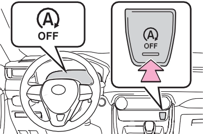
If the Stop & Start system is dis- abled using the Stop & Start cancel switch, it will be automatically re- enabled once the engine switch is turned off and then the engine is started.
rarily maintained to prevent the vehicle from rolling backwards before the engine is restarted and drive force is generated.
When drive force is generated, the maintained brake force is automatically canceled.
ing wheel may temporarily feel heavy.
(To enable the engine to be stopped by the Stop & Start sys- tem again, drive the vehicle.)
the Stop & Start system, the engine may restart automatically in the following situations: (To enable the engine to be stopped by the Stop & Start system again, drive the vehicle.)
Vehicles with an automatic air con- ditioning system: When the air con- ditioning is in automatic mode and the engine is stopped by the Stop & Start system, the fan may operate at a low speed in order to prevent the temperature in the cabin from increasing or decreasing or may be stopped.
To prioritize air conditioning system performance when the vehicle is stopped, disable the Stop & Start system by pressing the Stop & Start cancel switch.
(P.505, 505)
If the windshield fogs up frequently, press the Stop & Start cancel switch to disable the Stop & Start system.
If the idling stop time setting is set to “Extended”, change it to “Stan- dard”. If an odor is emitted when the idling stop time setting is set to “Standard”, press the Stop & Start cancel switch to deactivate the Stop & Start system.
Press the Stop & Start cancel switch to deactivate the Stop & Start system.
The length of time the Stop & Start system will operate when the air conditioning system is on can be
changed in of the multi-informa- tion display (P.94). (The length of time the Stop & Start system will operate when the air conditioning system is off cannot be changed.)
After Start:
Displays the cumulative time that the engine is stopped by the Stop & Start system from when the engine is started until the engine is stopped.
This item is reset each time the engine stops.
If the following situations,
and a message may be displayed on the multi-information display.
 “Press Brake More to Acti- vate”
If the brake pedal is depressed further, the system will operate.
 “Non-Dedicated Battery”
Have the vehicle inspected by your Toyota dealer.
 “Battery Charging”
Stopping of the engine is tempo- rarily prohibited to prioritize charging of the battery. After the engine runs for a certain amount of time, the sys- tem will be enabled.
After a refresh charge of approxi- mately 5 to 60 minutes completes, the system can be operated.
The battery may be deteriorated. Contact your Toyota dealer for details.
 “Stop & Start System Unavailable”
rarily disabled.
Allow the engine to run for some time.
Close the hood, turn the engine switch off, wait for 30 seconds or more, and then start the engine.
 “In Preparation”
When the brake booster vacuum reaches a predetermined level, the system will be enabled.
 “For Climate Control”
If the difference between the set temperature and cabin temperature becomes small, the system will be enabled.
 “In Preparation”
The system will be enabled after the engine runs and the brake booster vacuum reaches a predeter- mined level.
 “For Climate Control”
 “Battery Charging”
The engine is restarted to priori- tize battery charging. After the engine runs for a certain amount of time, the system will be enabled.
If the driver’s door is opened when the engine is stopped by the Stop & Start system and the shift lever is in D, a buzzer will sound and the Stop & Start system indicator will flash. To stop the buzzer, close the driver’s door.
P.651
The system may be malfunctioning. Have the vehicle inspected by your Toyota dealer.
The system may be malfunctioning. Have the vehicle inspected by your Toyota dealer.
|
|
|
When the Stop & Start system is operating
Make sure to disable the Stop & Start system while the vehicle is in a poorly ventilated area. If not disabled, the engine may be automatically restarted unexpect- edly, causing exhaust gases to collect and enter the vehicle, pos- sibly resulting in death or a seri- ous health hazard. Do not leave the vehicle while the engine is stopped by the Stop & Start system (while the Stop & Start indicator is on). An accident may occur due to the automatic engine start function.
Depress the brake pedal and apply the parking brake when necessary while the engine is stopped by the Stop & Start sys- tem (while the Stop & Start indi- cator is on).
|
 WARNING
|
|
|
To ensure the system oper- ates correctly
If any of the following situations occur, the Stop & Start system may not operate correctly. Have your vehicle inspected by your Toyota dealer. While the driver’s seat belt is fastened, the driver’s and front passenger’s seat belt reminder light flashes.
|
 NOTICE
|
|
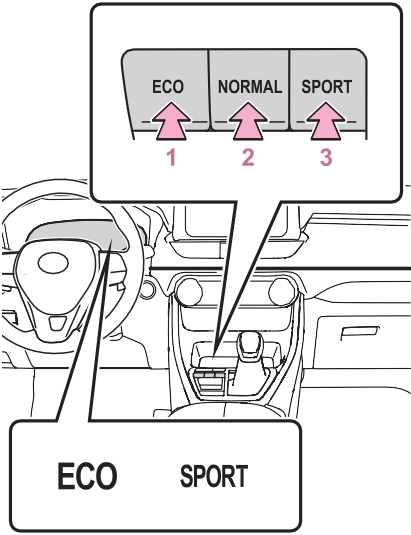
Suitable for driving to improve fuel economy by more smoothly gener- ating torque in response to acceler- ator pedal operations compared to normal mode and restraining air conditioning system operations (heating/cooling).
When the switch is pressed while not in Eco drive mode, the system switches to Eco drive mode and the
Eco drive mode indicator illumi- nates on the multi-information dis- play.
Suitable for normal driving.
The driving mode returns to normal mode if the switch is pressed while in Eco drive mode or sport mode.
Controls the steering feeling and engine to create an acceleration response that is suitable for sporty driving. Suitable for when crisp handling is desired, such as when driving on mountainous roads.
When the switch is pressed while not in sport mode, the system switches to sport mode and the sport mode indicator illuminates on the multi-information display.
Suitable for driving to improve fuel
economy by more smoothly gener- ating torque in response to acceler- ator pedal operations compared to normal mode and restraining air conditioning system operations (heating/cooling).
When the switch is pressed while not in Eco drive mode, the system switches to Eco drive mode and the Eco drive mode indicator illumi- nates on the multi-information dis- play.
Suitable for normal driving.
The driving mode returns to normal mode if the switch is pressed while in Eco drive mode or sport mode.
Controls the steering feeling and engine to create an acceleration response that is suitable for sporty driving. Suitable for when crisp handling is desired, such as when driving on mountainous roads.
When the switch is pressed while not in sport mode, the system switches to sport mode and the sport mode indicator illuminates on the multi-information display.
In Eco drive mode, heating/cooling operations and the fan speed is con- trolled to improve fuel efficiency.
Perform the following procedures to increase the air conditioning perfor- mance.
|
Changing the mode |
|
Guidelines for selecting each mode |
Suitable for driving on roads with increased driving resis- tance such as sandy roads, muddy roads, etc.
Suitable for driving in bumpy road conditions, such as on unpaved forest roads.
When the switch is pressed while not in Mud & Sand mode, the sys- tem switches to Mud & Sand mode and the Mud & Sand mode indica- tor, VSC OFF indicator and PCS warning light illuminate on the multi-information display.
Mode that performs AWD, brake and drive force control suitable for driving on general roads. Use nor- mal mode when not driving off- road.
The driving mode returns to normal mode if the switch is pressed while in Mud & Sand mode or Rock & Dirt mode.
When the switch is pressed while
not in Rock & Dirt mode, the sys- tem switches to Rock & Dirt mode and the Rock & Dirt mode indicator illuminates on the multi-information display.
When the switch is turned to the left while not in Mud & Sand mode, the system switches to Mud & Sand mode and the Mud & Sand mode indicator, VSC OFF indicator and PCS warning light illuminate on the multi-information display.
Mode that performs AWD, brake and drive force control suitable for driving on general roads. Use nor- mal mode when not driving off- road.
The driving mode returns to normal mode if the switch is pressed while in Mud & Sand mode or Rock & Dirt mode.
When the switch is turned to the right while not in Rock & Dirt mode, the system switches to Rock & Dirt mode and the Rock & Dirt mode indicator illuminates on the multi- information display.
If the vehicle speed exceeds the speeds listed below, 4WD control is performed similar to that performed in Normal mode, even if Mud & Sand or Rock & Dirt mode is selected.
If the vehicle speed drops below the above speeds, the system automati- cally switches to the 4WD control suitable for each mode.
If Mud & Sand or Rock & Dirt mode is continuously used for a long period of time, the brakes may over- heat, and Multi-terrain Select brake control may temporarily stop operat- ing.
*: After stopping the vehicle, do not stop the engine until the display message has turned off.
In the following situations, Mud & Sand mode or Rock & Dirt mode are automatically canceled even if they are selected.
The following types of situations may occur, but they are not malfunc- tions.
In the following situations, the sys- tem may be malfunctioning. Have the vehicle inspected by your Toyota dealer immediately.
*: If equipped
Press the snow mode switch.
When the switch is pressed, the system switches to snow mode and the snow mode indicator illuminates on the multi-information display.
When the switch is pressed again, the snow mode indicator turns off.
Press the snow mode switch.
When the switch is pressed, the system switches to snow mode and the snow mode indicator illuminates on the multi-information display.
When the switch is pressed again, the snow mode indicator turns off.
|
|
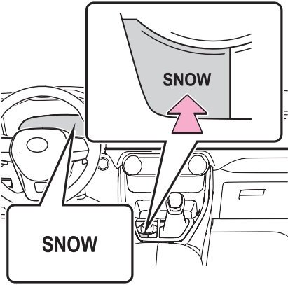
The background of the multi-infor- mation display changes.
Snow mode is automatically can- celed when the engine switch is turned off or Mud & Sand or Rock & Dirt mode is selected for Multi-ter- rain Select.
*: If equipped

The downhill assist control system indicator will come on and the sys- tem will operate.
When the system is in operation, the slip indicator light will flash, and the stop lights/high mounted stop lights will be lit. A sound may also occur during the operation. This does not indicated a malfunction.
|
Turning off the system |
The downhill assist control system indicator will flash as the system gradually ceases operation, and will turn off when the system is fully off. Press the “DAC” switch while the downhill assist control system indi- cator is flashing to start the system again.
The system will operate when the shift lever is in D or 1 range of S mode or R.
The system will gradually ceases
 operation. The indicator will flash during operation, and then go off when the system is fully off.
This may cause the brake actuator to overheat. In this case, the down- hill assist control system will stop operating, a buzzer will sound and the downhill assist control system indicator will start flashing. Refrain from using the system until the downhill assist control system indi- cator stays on and the message goes off. (The vehicle can be driven normally during this time.)
In the following cases, have your vehicle checked by your Toyota dealer.
Generates an increased level of braking force after the brake pedal is depressed when the system detects a panic stop sit- uation
Helps the driver to control skid- ding when swerving suddenly or turning on slippery road sur- faces.
Provides cooperative control of the ABS, TRAC, VSC and EPS.
Helps to maintain directional stability when swerving on slip- pery road surfaces by con- trolling steering performance.
Helps the driver to control trailer sway by selectively applying brake pressure for individual wheels and reducing driving torque when trailer sway is detected.
When the airbag sensor detects a collision, the brakes and brake lights are automatically con- trolled to reduce the vehicle speed and that helps reduce the possibility of further damage due to a secondary collision.
Helps to maintain drive power and prevent the drive wheels from spinning when starting the vehicle or accelerating on slip- pery roads
Helps to prevent the vehicle from drifting to the outer side by performing inner wheel brake control when attempting to accelerate during cornering
Helps to reduce the backward movement of the vehicle when starting on an uphill
Employs an electric motor to reduce the amount of effort needed to turn the steering wheel
Automatically switches from front-wheel drive to all-wheel drive (AWD) according to the driving conditions, helping to ensure reliable handling and stability. Examples of conditions where the system will switch to AWD are when cornering, going uphill, starting off or accelerat- ing, and when the road surface is slippery due to snow, rain, etc.
Automatically switches from front wheel drive to all-wheel drive (AWD) according to the driving conditions, helping to ensure reliable handling and stability. Examples of conditions where the system will switch to AWD are when cornering, going uphill, starting off or accelerat- ing, and when the road surface is slippery due to snow, rain, etc.
Also, when the vehicle is corner- ing, the drive torque distribution
between the front and rear wheels and between the rear left and right wheels is precisely controlled to improve drivability and stability.
The slip indicator light will flash while the TRAC/VSC/Trailer Sway Control systems are operating.
If the vehicle gets stuck in mud, dirt or snow, the TRAC system may reduce power from the engine to the wheels.
Pressing  to turn the system off may make it easier for you to rock the vehicle in order to free it.
To turn the TRAC system off, quickly press and release .
“Traction Control Turned OFF” will be shown on the multi-information display.
Press  again to turn the system back on.
To turn the TRAC/VSC/Trailer Sway Control systems off, press and hold
 for more than 3 seconds while the vehicle is stopped.
The VSC OFF indicator light will come on and the “Traction Control Turned OFF” will be shown on the multi-information display.*
Press  again to turn the systems back on.
*: PCS will also be disabled (only Pre-Collision warning is avail- able). The PCS warning light will come on and a message will be displayed on the multi-information display. (P.238)
been disabled even if has not been pressed
TRAC is temporary deactivated. If the information continues to show, contact your Toyota dealer.
When the following four conditions are met, the hill-start assist control will operate:
The hill-start assist control will turn off in any of the following situations:
After turning the TRAC, Trailer Sway Control and VSC systems off, the systems will be automatically re- enabled in the following situations:
If both the TRAC and VSC sys- tems are turned off, automatic re- enabling will not occur when vehi- cle speed increases.
When Active Cornering Assist is operated, operation sounds and vibrations may be generated from the brake system, but this is not a malfunction.
When the vehicle switches from AWD to front wheel drive and vice versa, operation sounds and vibra- tions may be generated, but this is not a malfunction.
When the steering wheel is oper- ated, a motor sound (whirring sound) may be heard. This does not indicate a malfunction.
The effectiveness of the EPS sys- tem is reduced to prevent the sys- tem from overheating when there is frequent steering input over an extended period of time. The steer- ing wheel may feel heavy as a result. Should this occur, refrain from excessive steering input or stop the vehicle and turn the engine off. The EPS system should return to normal within 10 minutes.
The vehicle speed is approximately 6 mph (10 km/h) or more and the airbag sensor detects a collision. (The Secondary Collision Brake will not operate when the vehicle speed is below approximately 6 mph [10 km/h].)
The Secondary Collision Brake is automatically canceled in the follow- ing situations:
approximately 6 mph (10 km/h)
The system operates in the follow- ing situations.
Perform the following actions.
|
Message |
Details/Actions |
|
“AWD System Over- heated Switching to 2WD Mode” |
AWD system is overheating. Perform the following actions. Reduce the vehicle speed until the message disappears.
Stop the vehicle in a safe place and let the engine idle.*
Once the display message on the multi-informa- tion display turns off, there is no problem continu- ing to drive. If the message does not disappear, have your vehicle checked by your Toyota dealer immedi- ately. |
|
“AWD System Over- heated 2WD Mode Engaged” |
The vehicle switched from all-wheel drive (AWD) to front wheel drive due to overheating. Perform the following actions. Reduce the vehicle speed until the message disappears.
Stop the vehicle in a safe place and let the engine idle.*
Once the display message on the multi-informa- tion display turns off, the AWD system returns to normal. If the message does not disappear, have your vehicle checked by your Toyota dealer immedi- ately. |
|
“AWD System Malfunc- tion 2WD Mode Engaged Visit Your Dealer” |
A malfunction occurred in the AWD system. Have your vehicle checked by your Toyota dealer immediately. |
*: Dynamic Torque Control AWD vehicles only. After stopping the vehicle, do not stop the engine until the display message has turned off.
|
Pre-winter preparations |
Ensure that all tires are the same size and brand, and that chains match the size of the tires.
*: Tire chains cannot be mounted on vehicles with 235/55R19 101V tires.
Download Manual