Do-it-yourself maintenance
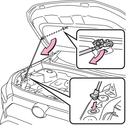
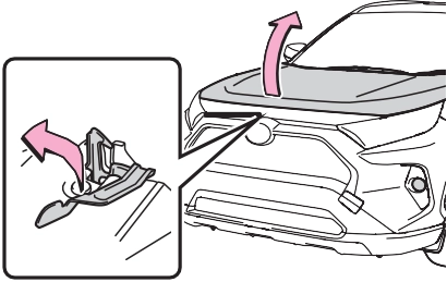
The hood will pop up slightly.
|
|
|
|
|
|
|
When closing the hood
Be sure to return the support rod to its clip before closing the hood. Closing the hood without return- ing the support rod properly could cause the hood to bend. |
 NOTICE
|
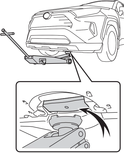
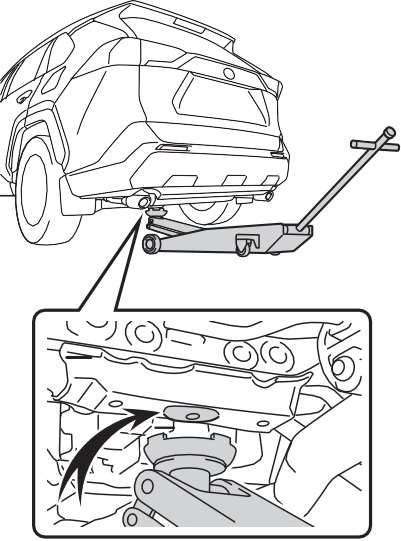
Location of the jack point |
|
|
|
|
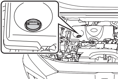
Engine compartment
Fuse box (if equipped) (P.597) Engine oil filler cap (P.566) Engine oil level dipstick (P.566) Battery (P.571)
Brake fluid reservoir (P.569) Radiator (P.569)
Electric cooling fan Condenser (P.569) Washer fluid tank (P.572)
Engine coolant reservoir (P.568)
check the oil level on the dip- stick.
With the engine at operating temperature and turned off,
Low Normal Excessive
The shape of the dipstick may differ depending on the type of vehicle or engine.
Make sure to check the oil type and prepare the items needed before adding oil.
P.660
1.6 qt. (1.5 L, 1.3 lmp.qt.)
Clean funnel
|
|
A certain amount of engine oil will be consumed while driving. In the following situations, oil consump-
tion may increase, and engine oil may need to be refilled in between oil maintenance intervals.
|
|
|
Used engine oil
Used engine oil contains poten- tially harmful contaminants which may cause skin disorders such as inflammation and skin cancer, so care should be taken to avoid prolonged and repeated contact. To remove used engine oil from your skin, wash thoroughly with soap and water.
Dispose of used oil and filters only in a safe and acceptable manner. Do not dispose of used oil and filters in household trash, in sewers or onto the ground. Call your Toyota dealer, service station or auto parts store for information concerning recy- cling or disposal.
Do not leave used engine oil within the reach of children.
|
 WARNING

|
When replacing the engine oil
Be careful not to spill engine oil on the vehicle components.
Avoid overfilling, or the engine could be damaged.
Check the oil level on the dip- stick every time you refill the vehicle.
Be sure the engine oil filler cap is properly tightened.
If oil is spilled on the engine cover
To prevent the engine cover from being damaged, remove any engine oil from the engine cover as soon as possible using a neu- tral detergent. Do not use an organic solvent such as brake cleaner. |
|
Checking the coolant |
|
|
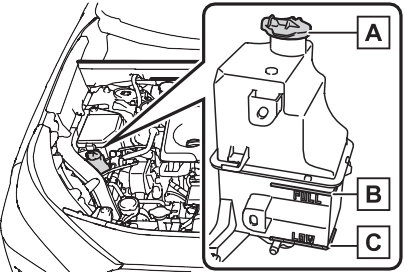
Reservoir cap “FULL” line “LOW” line
If the level is on or below the “LOW” line, add coolant up to the “FULL” line. (P.653)
Only use “Toyota Super Long Life Coolant” or a similar high quality ethylene glycol based non-silicate, non-amine, non-nitrite, and non- borate coolant with long-life hybrid organic acid technology.
U.S.A.:
“Toyota Super Long Life Coolant” is a mixture of 50% coolant and 50% deionized water. (Minimum tem- perature: -31°F [-35°C])
Canada:
“Toyota Super Long Life Coolant” is a mixture of 55% coolant and 45% deionized water. (Minimum tem- perature: -44°F [-42°C])
For more details about coolant, con- tact your Toyota dealer.
Visually check the radiators, hoses, engine/power control unit coolant reservoir caps, drain cock and water pump.
If you cannot find a leak, have your Toyota dealer, test the cap and check for leaks in the cooling sys- tem.
|
|
|
When the engine is hot
Do not remove the engine coolant reservoir cap. The cooling system may be under pressure and may spray hot cool- ant if the cap is removed, causing serious injuries, such as burns. |
 WARNING
|
Checking the radiator and condenser |
 If either of the above parts is extremely dirty or you are not sure of their condition, have your vehicle inspected by your Toyota dealer.
The brake fluid level should be between the “MAX” and “MIN” lines on the tank.
Make sure to check the fluid type and prepare the necessary item.
|
Fluid type |
FMVSS No.116 DOT 3 or SAE J1703 brake fluid FMVSS No.116 DOT 4 or SAE J1704 |
|
Item |
Clean funnel |
Excess moisture in the brake fluid can cause a dangerous loss of brak- ing efficiency. Use only newly opened brake fluid.
|
|
|
When filling the reservoir
Take care as brake fluid can harm your hands and eyes and damage painted surfaces. If fluid gets on your hands or in your eyes, flush the affected area with clean water immediately. If you still experience discomfort, see a doctor. |
 WARNING

Make sure that the battery termi- nals are not corroded and that there are no loose connections, cracks, or loose clamps.
Terminals
Hold-down clamp
When recharging, the battery pro- duces hydrogen gas which is flam- mable and explosive. Therefore, observe the following precautions before recharging:
cables to the battery.
The engine may not start. Follow the procedure below to initialize the sys- tem.
If the engine will not start even after multiple attempts, contact your Toy- ota dealer.

|
|
|
When recharging the battery
Never recharge the battery while the engine is running. Also, be sure all accessories are turned off. |
 NOTICE
|
Adding the washer fluid |
Tires
|
Checking tires |
 Check if the treadwear indica- tors are showing on the tires. Also check the tires for uneven wear, such as excessive wear on one side of the tread.
Check the spare tire condition and pressure if not rotated.
|
|
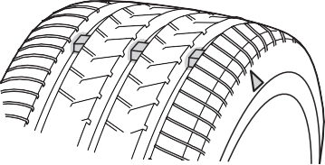
New tread Worn tread
Treadwear indicator
The location of treadwear indicators is shown by a “TWI” or “ ” mark,
etc., molded into the sidewall of each tire.
Replace the tires if the treadwear indicators are showing on a tire.
Summer tires are high-speed perfor- mance tires best suited to highway driving under dry conditions. Since summer tires do not have the same
traction performance as snow tires,
Tires should be replaced if:
If you are not sure, consult with your Toyota dealer.
Any tire over 6 years old must be checked by a qualified technician even if it has seldom or never been used or damage is not obvious.
Check that the maximum load of the replacement tire is greater than 1/2 of the Gross Axle Weight Ratings (GAWR) of either the front axle or the rear axle, whichever is greater.
For the GAWR, see the Certification Regulation Label. For the maximum load of the tire, see the load limit at maximum cold tire inflation pressure mentioned on the sidewall of the tire. (P.671)
summer tires are inadequate for driving on snow-covered or icy roads. For driving on snow-covered roads or icy roads, the use of snow tires is recommended. When install- ing snow tires, be sure to replace all four tires.
All season tires are designed to pro- vide better traction in snow and to be adequate for driving in most win- ter conditions as well as for use year-round. All season tires, how- ever, do not have adequate traction performance compared with snow tires in heavy or loose snow. Also, all season tires fall short in accelera- tion and handling performance com- pared with summer tires in highway driving.
For driving on snow-covered roads or icy roads, we recommend using snow tires. If you need snow tires, select tires of the same size, con- struction and load capacity as the originally installed tires. Since your vehicle has radial tires as original equipment, make sure your snow tires also have radial construction. Do not install studded tires without first checking local regulations for possible restrictions. Snow tires should be installed on all wheels. (P.369)
The effectiveness of the tires as snow tires is lost.

|
Tire rotation |
To equalize tire wear and extend tire life, Toyota recommends that tire rotation is carried out at the same interval as tire inspection.
Do not fail to initialize the tire pres- sure warning system after tire rota- tion. (if equipped)
Make sure that the engine switch is OFF. If the tires are rotated while the engine switch is in ON, the tire posi- tion information will not be updated. If this accidentally occurs, either turn the engine switch to OFF and then to ON, or initialize the system after checking that the tire pressure is properly adjusted.
*: Vehicles with tire inflation pres- sure display function only
The illustration used is intended as an example, and may differ from the image that is actually displayed on the multi-informa- tion display.
The tire pressure warning system does not replace routine tire inflation pressure checks. Make sure to check tire inflation pressure as part of your routine of daily vehicle checks.
*: Vehicles with tire inflation pres- sure display function only
warning valves and transmitters are used.
If tire position information is not cor- rectly displayed due to the radio wave conditions, the display may be corrected by driving and changing
the radio wave conditions.
The warning of the tire pressure warning system will change in accordance with the conditions under which it was initialized. For this reason, the system may give a warning even if the tire pressure does not reach a low enough level, or if the pressure is higher than the pressure that was adjusted to when the system was initialized.
’ For vehicles sold in the U.S.A., Hawaii, American Samoa, Guam, Saipan and Puerto Rico
’ For vehicles sold in Canada
*1: Vehicles with tire pressure warn- ing system only
’ Except for models made in Japan*2 without tire inflation pressure display function
When new tire pressure warning valves and transmitters are installed, new ID codes must be registered in the tire pressure warning computer and the tire pressure warning system must be initialized. (P.582)
*2: The country of production is writ- ten on the Certification Regula- tion label. (P.659)
When new tire pressure warning valves and transmitters are installed, new ID codes must be registered in the tire pressure warning computer and the tire pressure warning system must be initialized. Have tire pressure warning valve and transmitter ID codes registered by your Toyota dealer.
*2: The country of production is writ- ten on the Certification Regula- tion label. (P.659)
If the ID code of the tire pressure warning valve and transmitter is not registered, the tire pressure warning system will not work properly. After driving for about 20 minutes, the tire pressure warning light blinks for 1 minute and stays on to indicate a system malfunction.
When the tire pressure warning system is initialized, the current tire inflation pressure is set as the benchmark pressure.
’ Vehicles without tire inflation pressure display function
Initialization cannot be performed while the vehicle is moving.
Make sure to adjust the tire pres- sure to the specified cold tire infla- tion pressure level. The tire pressure warning system will oper- ate based on this pressure level.
 ing wheel and select .
or of the meter
4 Press
or of the meter
control switches, select “Vehicle Settings” and then
press  .
.
“TPWS” and then press  .
.
and hold  .
.
“Setting Tire Pressure Warning System” will be displayed on the multi-information display and the tire pressure warning light will blink 3 times.
When the message disappears, ini- tialization is complete.
Initialization cannot be performed while the vehicle is moving.
Make sure to adjust the tire pres- sure to the specified cold tire infla- tion pressure level. The tire pressure warning system will oper- ate based on this pressure level.
control switches on the steer- ing wheel and select  .
.
press  .
.
“TPWS” and then press  .
.
and hold  .
.
“Setting Tire Pressure Warning System” will be displayed on the multi-information display and the tire pressure warning light will blink 3 times.
When the message disappears, ini- tialization is complete.
A message is displayed on the multi-information display. Also, “--” is displayed for inflation pressure of each tire on the multi-information display while the tire pressure warning system determines the position.
more for approximately 10 to 30 minutes.
When initialization is complete, the inflation pressure of each tire will be displayed on the multi-information display.
Even if the vehicle is not driven at approximately 25 mph (40 km/h) or more, initialization can be com- pleted by driving for a long time.
However, if initialization does not complete after driving for 1 hour or more, park the vehicle in a safe place for approximately 20 minutes and then drive the vehicle again.
Initialization can be completed in a few minutes. However, in the follow-
ing cases, the settings have not
been recorded and the system will not operate properly. If repeated attempts to record tire inflation pres- sure settings are unsuccessful, have the vehicle inspected by your Toyota dealer.
In the following situations, initializa- tion may take longer than usual to be completed or may not be possi- ble. Normally, initialization com- pletes within approximately 30 minutes.
over those of other vehicles.
If initialization does not complete after driving for 1 hour or more, park the vehicle in a safe place for approximately 20 minutes and then drive the vehicle again.
If the inflation pressure of each tire is still not displayed, have the vehi- cle inspected by your Toyota dealer.

|
Registering ID codes (vehicles with tire pres- sure warning system) |
Every tire pressure warning valve and transmitter has a unique ID code. In addition to the set of tire pressure warning system sensor ID codes initially registered to the vehicle, a sec- ond set of ID codes can be reg- istered. A second set of tire pressure warning system sensor ID codes can be registered at your Toyota dealer. When 2 sets of ID codes have been regis- tered, either ID code set can be selected.
*1: The country of production is writ- ten on the Certification Regula- tion label. (P.659)
*2: The country of production is writ- ten on the Certification Regula- tion label. (P.659)
When registering the ID codes, perform the following procedure.
ing wheel and select  .
.
press  .
.
“TPWS”, and then press  .
.
and hold  until the tire pressure warning light starts slowly blinking 3 times.
The change wheel set mode is acti- vated and registration is started.
Vehicles with a tire inflation pres- sure display function only: Then a message will be displayed on the multi-information display. When registration is being performed, the tire pressure warning light will blink for approximately 1 minute then illu- minate and “--” will be displayed for the inflation pressure of each tire on
the multi-information display.
When registration is completed, the tire pressure warning light will go off and the inflation pressure of each tire will be displayed on the multi- information display.
Even if the vehicle is not driven at approximately 25 mph (40 km/h) or more, registration can be com- pleted by driving for a long time.
However, if registration does not complete after driving for 1 hour or more, perform the procedure again from the beginning.
In the following situations, ID code registration may take longer than usual to be completed or may not be possible. Normally, registration com- pletes within approximately 30 min- utes.
and transmitters of your vehicle over those of other vehicles
If registration does not complete after driving for 1 hour or more, per- form the ID code registration proce- dure again from the beginning.
If the ID codes cannot be registered even when performing the above procedure, contact your Toyota dealer.
Tire valve
Tire pressure gauge
You should check tire inflation pres- sure every two weeks, or at least once a month.
 Do not forget to check the spare.
Driving with incorrect tire inflation pressure may result in the following:
If a tire needs frequent inflating, have it checked by your Toyota dealer.
When checking tire inflation pres- sure, observe the following:
If your vehicle has been parked for at least 3 hours or has not been driven for more than 1 mile or 1.5 km, you will get an accurate cold tire inflation pressure reading.
|
Wheel selection |
Replacement wheels are avail- able at your Toyota dealer.
*: Conventionally referred to as off- set.
The wheels of your vehicle are equipped with tire pressure warning valves and transmitters that allow the tire pressure warning system to provide advance warning in the event of a loss in tire inflation pres- sure. Whenever wheels are replaced, tire pressure warning valves and transmitters must be installed. (P.576, 588)
|
|
|
Use of defective wheels pro- hibited
Do not use cracked or deformed wheels. Doing so could cause the tire to leak air during driving, possibly causing an accident. |
 WARNING
|
|
|
Replacing tire pressure warn- ing valves and transmitters (vehicles with tire pressure warning system)
Because tire repair or replace- ment may affect the tire pres- sure warning valves and transmitters, make sure to have tires serviced by your Toyota dealer or other qualified service shop. In addition, make sure to purchase your tire pressure warning valves and transmit- ters at your Toyota dealer.
Ensure that only genuine Toyota wheels are used on your vehi- cle.
Tire pressure warning valves and transmitters may not work properly with non-genuine wheels. |
 NOTICE
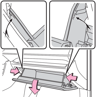
Air conditioning filter
4 With the glove box fully open, slightly lift up the glove box and pull toward the seat to detach the bottom of the glove box.
Do not use excessive force if the glove box does not detach when lightly pulled. Instead, pull toward the seat while slightly adjusting the height of the glove box.
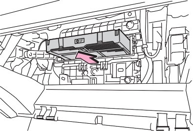
pull the filter cover out of the
claws ( B ), and remove the
3 Push in each side of the glove box to disconnect the claws, and then slowly and fully open the glove box while supporting it.
filter cover.
|
|
|
|
The “ UP” marks shown on the filter should be pointing up.
|
|
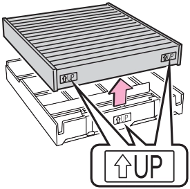
Inspect and replace the air condi- tioning filter according to the mainte- nance schedule. In dusty areas or areas with heavy traffic flow, early replacement may be required. (For scheduled maintenance information, please refer to the “Owner’s Manual Supplement” or “Scheduled Mainte- nance”.)
The filter may be clogged. Check the filter and replace if necessary.
driver with a rag.
When returning the wiper arms to their original positions, first lower the passenger side, and then lower the driver side.
To prevent damage to the wiper arm, protect the tip of the screw-
When installing, reverse the steps listed.
|
|
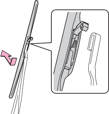
Stopper Claw
from the wiper insert pulled out, and install the plates to a new wiper insert.
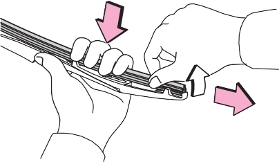
the claw detaches, and then remove the wiper blade from the wiper arm.
Make sure that the cutout location and warp direction of the metal blades are same as the original.
Lightly grasp between the claws of the wiper blade to allow the wiper insert to lift up, making it easier to remove.
|
|
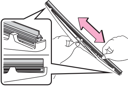
install them to the replace- ment wiper insert.
Applying a small amount of washer fluid to the wiper insert can make it easier to insert the claws into the grooves.
If the wiper blade claws are not fit- ted in the grooves of the wiper insert, grasp the wiper insert and slide it back and forth multiple times to insert the claws into the grooves.
Lightly lift up the center of the wiper insert to make the rubber easier to
slide.
|
|
After installing the wiper blade, check that the connection is locked.
Improper handling may result in damage to the wiper blades or wiper insert. If you have any concerns about replacing the wiper blades or wiper insert yourself, contact your Toyota dealer.
|
|
|
When lifting the windshield wipers
When raising the wiper arms off the windshield, lift up the driver side first, and then lift up pas- senger side. When returning the wipers to their original position, return the passenger side first.
Do not lift a windshield wiper by the wiper blade. Otherwise, the wiper blade may be deformed.
Do not operate the wiper lever when the windshield wipers are lifted. Otherwise, the wind- shield wipers may contact the hood, possibly resulting in dam- age to the windshield wipers and/or hood.
|
 NOTICE
The following symptoms may occur:
|
Items to prepare |
|
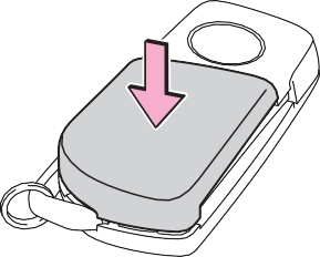
Replacing the battery |
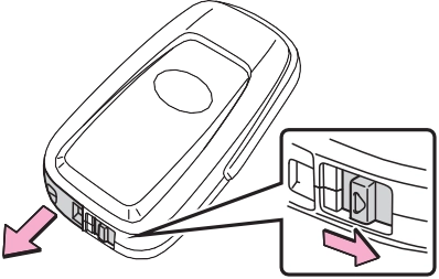
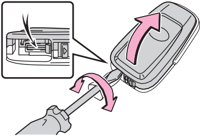
1 Remove the cover.
Use a screwdriver of an appropriate size. Forcedly prying may cause the cover damaged.
To prevent damage to the key, cover the tip of the screwdriver with a rag.
If the battery cover is difficult to remove, lift the edge to remove it.
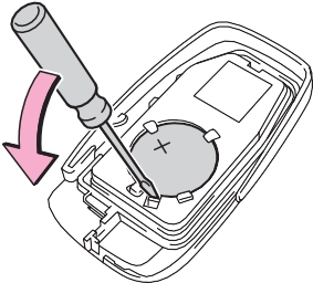
When removing the battery, use a screwdriver of an appropriate size.
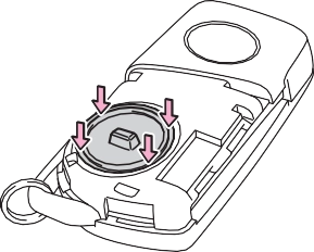
Insert a new battery with the “+” ter- minal facing up.
Push the entire edge of the battery
cover into the key.
|
|
Align the key cover with the key and then press it straight into the key.
Make sure that the key cover is securely installed without any gaps between it and the key.
|
|
|
|
Use a screwdriver of an appropriate size. Forcedly prying may cause
 the cover damaged.
To prevent damage to the key, cover the tip of the flathead screw- driver with a rag.
|
|
When removing the cover, the elec- tronic key module may stick to the cover and the battery may not be visible. In this case, remove the electronic key module in order to remove the battery.
When removing the battery, use a screwdriver of an appropriate size.
Insert a new battery with the “+” ter- minal facing up.
|
|
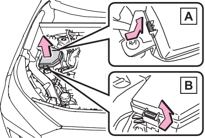
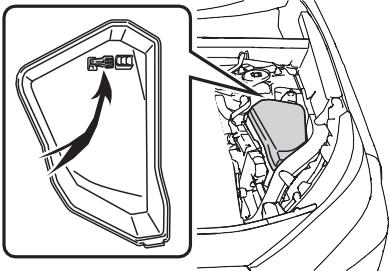
’ Engine compartment: Type B fuse box
Push claw ( A
) to com-
pletely release the lock, and then lift up the cover.
|
Checking and replacing fuses |
’ Engine compartment: Type A fuse box (if equipped)
’ Left side instrument panel
Remove the lid.
Push claw ( A
) to com-
pletely release the lock, and then lift up the cover.
|
|
Only type A fuse can be removed using the pullout tool.
|
|
Replace the blown fuse with a new fuse of an appropriate amperage rating. The amperage rating can be
found on the fuse box lid.
’ Type A
’ Type B
’ Type C
The fuses are designed to blow, pro- tecting the wiring harness from damage.
|
|
|
To prevent system break- downs and vehicle fire
Observe the following precau- tions. Failure to do so may cause dam- age to the vehicle, and possibly a fire or injury. Never use a fuse of a higher amperage rating than that indi- cated, or use any other object in place of a fuse.
Always use a genuine Toyota fuse or equivalent.
Never replace a fuse with a wire, even as a temporary fix. Do not modify the fuses or fuse boxes.
|
 WARNING
|
|
|
Before replacing fuses
Have the cause of electrical over- load determined and repaired by your Toyota dealer as soon as possible. |
 NOTICE
|
Preparing for light bulb replacement |
|
Bulb location |
’ Front (type A)
|
|
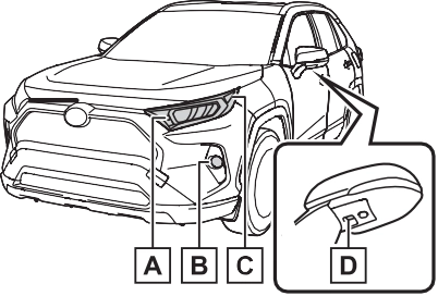
Front turn signal/parking lights
Fog lights (if equipped) Front side marker lights
Outer foot lights (if equipped)
’ Front (type B)
Front turn signal/parking lights
Fog lights
Front side marker lights Outer foot lights
’ Rear
replaced by your Toyota dealer
The lights other than the following lights each consist of a number of LEDs. If any of the LEDs burn out, take your vehicle to your Toyota dealer to have the light replaced.
Temporary condensation build-up on the inside of the light lens does not indicate a malfunction. Contact your Toyota dealer for more informa- tion in the following situations:
|
|
|
|
|
|
|
|
|
|
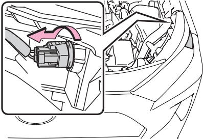
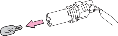
Align the 3 tabs on the light bulb with the mounting, and insert. Turn it clockwise to set.
Shake the bulb base gently to check that it is not loose, turn the front fog lights on once and visually confirm that no light is leaking through the mounting.
|
|
|
|
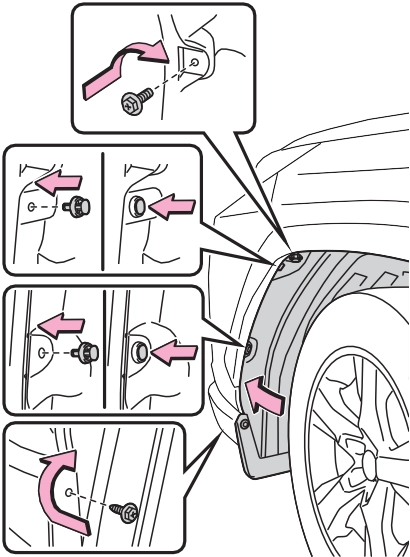
1 Open the back door and remove the cover.
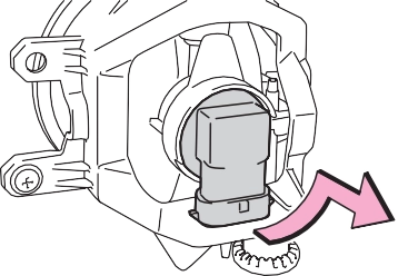
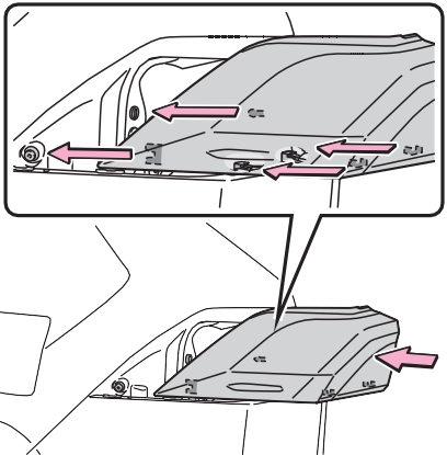
Remove the lamp assembly by pull- ing it directly backward from the rear of the vehicle.
turning the bulb base clock- wise.
Confirm that the light unit is com- pletely secured.
|
|
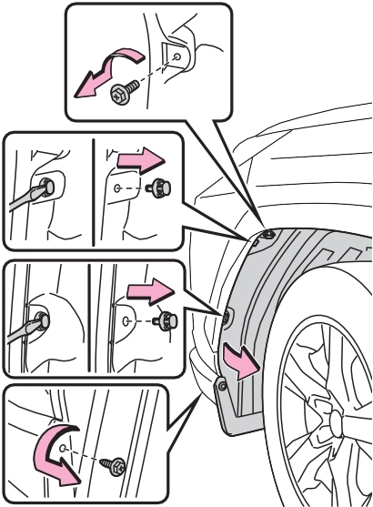
To prevent damage to the cover, protect the tip of the screwdriver with a rag.
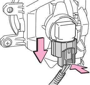
Remove the cord from the clip
before turning the bulb base.
|
|
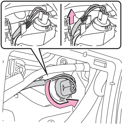
Secure the cord with the clip back
again after installing the bulb base.
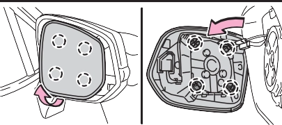
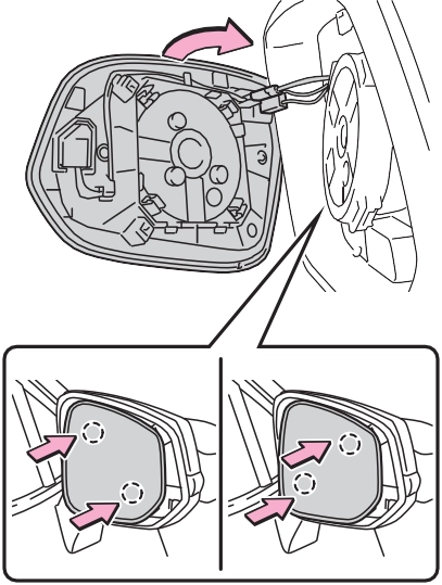
1 Press the upper part of the outside rear view mirror to tilt the mirror face upward, and disconnect the four tabs behind the mirror.
Pry the mirror out toward you, and disconnect two tabs at a time.
Work carefully, ensuring that you do
not drop the mirror.
|
|
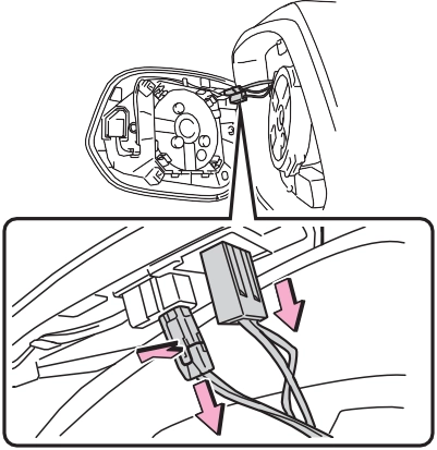
Make sure to check the connectors, to avoid connecting upside down when reinstalling.
Work carefully, ensuring that you do not drop the mirror.
|
|
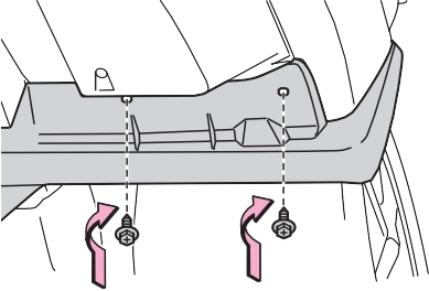
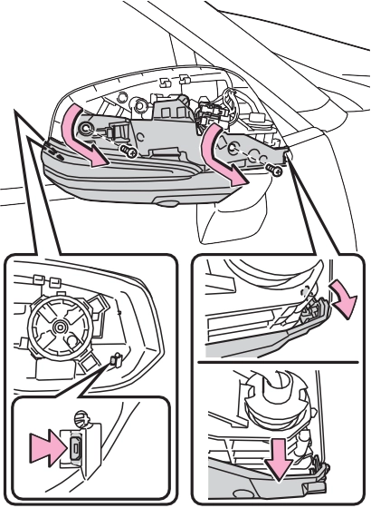
Remove the two screws, and disen- gage the two tabs with a flat-head screwdriver.
Work carefully, ensuring that you do
not damage the tabs.
|
|
Remove the cord from the clip before turning the bulb base.
Secure the cord with the clip back again after installing the bulb base.
Make sure that the two tabs of the light unit are engaged securely, and
install the two screws.
11Install the mirror cover.
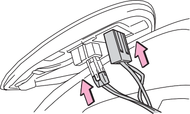
 12Reconnect the connectors of the mirror.
|
|
13Align the tabs, and secure the mirror by pushing in each diagonally-opposite pair of tabs in order.
Make sure to insert the tabs in order as shown in the illustration, and push them in until a click is heard.
If you do not hear the click, do not force the tabs in. Instead, remove the mirror and check that the tabs are aligned.
|
|
When trouble arises 8
611
.................................. 621
If a warning light turns on or a warning buzzer sounds
.................................. 622
If your vehicle overheats
.................................. 653
If the vehicle becomes stuck
.................................. 655
8
Download Manual