Steps to take in an emergency
|
|
|
Observe the following precau- tions. Failure to do so may result in death or serious injury. |
 WARNING
|
Situations when it is nec- essary to contact dealers before towing |
commercial towing service before towing.
617
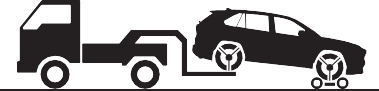
Do not tow with a sling-type truck to prevent body damage.
’ From the front (2WD models) Release the parking brake.
’ From the front (AWD models)
Use a towing dolly under the rear wheels.
’ From the rear
Use a towing dolly under the front wheels.
|
|
|
Using a flatbed truck |
If your vehicle is transported by a flatbed truck, it should be tied down at the locations shown in the illustration.
8
|
|
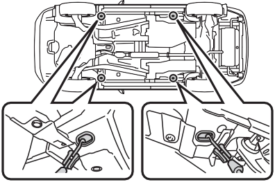
If you use chains or cables to tie down your vehicle, the angles shaded in black must be 45°.
Do not overly tighten the tie
downs or the vehicle may be damaged.
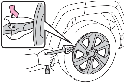
remove eyelet cover ( A ), and then remove eyelet
cover ( B ).
To protect the bodywork, place a rag between the screwdriver and the vehicle body as shown in the illustration.
’ Type A
|
Emergency towing (vehi- cles with towing eyelet) |
mph (30 km/h).
A driver must be in the vehicle to steer and operate the brakes.
The vehicle’s wheels, drive train, axles, steering and brakes must be in good condition.
To have your vehicle towed by another vehicle, the towing eye- let must be installed to your vehicle. Install the towing eyelet by following the specified proce- dure.
’ Type B
’ Type A
’ Type B
619
’ Type B
’ Type A
Take care not to damage the vehi- cle body.
Turn off the Parking Support Brake function. (if equipped): P.284
If the engine does not start, turn the engine switch to ON.
Vehicles with Stop & Start system: Before towing the vehicle, turn the engine switch to OFF once, and then start the engine.
When the shift lever cannot be shifted: P.202
8
If the engine is not running, the power assist for the brakes and steering will not function, making steering and braking more difficult.
Wheel nut wrench is installed in the tool bag. (P.637)
|
Visible symptoms |
|
Audible symptoms |
|
Operational symptoms |
621
|
Restarting the engine |
8
|
Warning light |
Details/Actions |
|
(U.S.A.) (Canada) (Red) |
Indicates that: The brake fluid level is low; or
The brake system is malfunctioning
Immediately stop the vehicle in a safe place and contact your Toyota dealer. Continuing to drive the vehicle may be dangerous. |
|
Warning light |
Details/Actions |
|
(Yellow) |
Indicates a malfunction in the parking brake sys- tem Have the vehicle inspected by your Toyota dealer immediately. |
|
Warning light |
Details/Actions |
|
Indicates a malfunction in the vehicle’s charging system Immediately stop the vehicle in a safe place and contact your Toyota dealer. |
8-2. Steps to take in an emergency
623
|
Warning light |
Details/Actions |
|
Indicates that the engine is overheating Immediately stop the vehicle in a safe place. Handling method (P.653) |
*: This light illuminates on the multi-information display with a message.
|
Warning light |
Details/Actions |
|
Indicates that the engine oil pressure is too low Immediately stop the vehicle in a safe place and contact your Toyota dealer. |
*: This light illuminates on the multi-information display with a message.
|
Warning light |
Details/Actions |
|
(U.S.A.) (Canada) |
Indicates a malfunction in: The electronic engine control system;
The electronic throttle control system; or
The emission control system (if equipped)
Have the vehicle inspected by your Toyota dealer immediately. |
8
|
Warning light |
Details/Actions |
|
(U.S.A.) (Canada) |
Indicates a malfunction in: The ABS; or
The brake assist system
Have the vehicle inspected by your Toyota dealer immediately. |
|
Warning light |
Details/Actions |
|
(Red/yellow) |
Indicates a malfunction in the EPS (Electric Power Steering) system Have the vehicle inspected by your Toyota dealer immediately. |
|
Warning light |
Details/Actions |
|
(Flashes or illuminates) |
When a buzzer sounds simultaneously: Indicates a malfunction has occurred in the PCS (Pre-Collision System). Have the vehicle inspected by your Toyota dealer immediately. When a buzzer does not sound: The PCS (Pre-Collision System) has become temporarily unavailable, corrective action may be necessary. Follow the instructions displayed on the multi-information display. (P.229, 635) If the PCS (Pre-Collision System) or VSC (Vehi- cle Stability Control) system is disabled, the PCS warning light will illuminate. P.238 |
8-2. Steps to take in an emergency
625
8
|
Warning light |
Details/Actions |
|
(Flashes) (If equipped) |
When a buzzer sounds: Indicates a malfunction in the PKSB (Parking Support Brake) system Have the vehicle inspected by your Toyota dealer immediately. When a buzzer does not sound: Indicates that the system is temporarily unavail- able, possibly due to a sensor being dirty or cov- ered with ice, etc. Follow the instructions displayed on the multi-information display. (P.282, 633) |
|
Warning light |
Details/Actions |
|
(Flashes) (If equipped) |
When a buzzer sounds: Indicates a malfunction in the RCTA (Rear Cross Traffic Alert) function Have the vehicle inspected by your Toyota dealer immediately. When a buzzer does not sound: Indicates that the rear bumper around the radar sensor is covered with dirt, etc. (P.265) Follow the instructions displayed on the multi-information display. (P.264, 633) |
|
Warning light |
Details/Actions |
|
Indicates a malfunction in: The VSC/Trailer Sway Control system;
The TRAC system;
The hill-start assist control system; or
The downhill assist control system (if equipped)
Have the vehicle inspected by your Toyota dealer immediately. |
8-2. Steps to take in an emergency
627
8
*: This light illuminates on the multi-information display with a message.
|
Warning light |
Details/Actions |
|
(Flashes) |
Indicates a malfunction in the brake hold system Have the vehicle inspected by your Toyota dealer immediately. |
|
Warning light |
Details/Actions |
|
|
It is possible that the parking brake is not fully engaged or released |
|
(U.S.A.) (Flashes) |
Operate the parking brake switch once again. |
|
(Canada) (Flashes) |
This light comes on when the parking brake is not released. If the light turns off after the park- ing brake is fully released, the system is operat- ing normally. |

|
Warning light |
Details/Actions |
|
Indicates that remaining fuel is approximately 2.2 gal. (8.3 L, 1.8 Imp. gal.) or less Refuel the vehicle. |
Driver’s and front passenger’s seat belt reminder light (warn- ing buzzer*)
|
Warning light |
Details/Actions |
|
Warns the driver and/or front passenger to fas- ten their seat belts Fasten the seat belt. If the front passenger’s seat is occupied, the front passenger’s seat belt also needs to be fastened to make the warning light (warning buzzer) turn off. |
*: Driver’s seat belt warning buzzer:
The driver’s seat belt warning buzzer sounds to alert the driver that his or her seat belt is not fastened. Once the engine switch is turned to ON, the buzzer sounds for 6 seconds. If the vehicle reaches a speed of 12 mph (20 km/h), the buzzer sounds once. If the seat belt is still unfastened after 24 seconds, the buzzer will sound intermittently for 6 seconds. Then, if the seat belt is still unfastened, the buzzer will sound in a different tone for 90 more seconds.
Front passenger’s seat belt warning buzzer:
The front passenger’s seat belt warning buzzer sounds to alert the front passenger that his or her seat belt is not fastened. The buzzer sounds once if the vehicle reaches a speed of 12 mph (20 km/h). If the seat belt is still unfastened after 24 seconds, the buzzer will sound intermittently for 6
629
seconds. Then, if the seat belt is still unfastened, the buzzer will sound in a different tone for 90 more seconds.
|
Warning light |
Details/Actions |
|
(If equipped) |
Warns the rear passengers to fasten their seat belts Fasten the seat belt. |
*: Rear passengers’ seat belt warning buzzer:
The rear passengers’ seat belt warning buzzer sounds to alert the rear passengers that his or her seat belt is not fastened. The buzzer sounds once if the vehicle reaches a speed of 12 mph (20 km/h). If the seat belt is still unfastened after 24 seconds, the buzzer will sound intermittently for 6 seconds. Then, if the seat belt is still unfastened, the buzzer will sound in a different tone for 30 more seconds.
8
In some cases, the buzzer may not be heard because of noisy place or an audio sound.
warning buzzer to sound even if a passenger is not sitting in the seat.
This warning light system monitors the airbag sensor assembly, front impact sensors, side impact sensors (front door), side impact sensors
(front), side impact sensors (rear), driver’s seat position sensor, driver’s seat belt buckle switch, front passenger occupant classification system (ECU and sensors), “AIR BAG ON” indicator light, “AIR BAG OFF” indicator light, front passen- ger’s seat belt buckle switch, seat belt pretensioners and force limiters, airbags, interconnecting wiring and power sources. (P.34)
First check the following:
If it is, fill the fuel tank immediately.
The light will go off after several driving trips.
If the light does not go off even after several trips, contact your Toyota dealer as soon as possible.
When the battery charge becomes insufficient or the voltage temporar- ily drops, the electric power steering system warning light may come on and the warning buzzer may sound.
Inspect the tires to check if a tire is punctured.
If a tire is punctured: P.636
If none of the tires are punctured:
Turn the engine switch to OFF then turn it to ON. Check if the tire pres- sure warning light comes on or blinks.
’ If the tire pressure warning light blinks for approximately 1 minute then stays on
There may be a malfunction in the tire pressure warning system. Have
the vehicle inspected by your Toyota dealer immediately.
’ If the tire pressure warning light comes on
The tire pressure warning light may come on due to natural causes such as natural air leaks and tire inflation pressure changes caused by tem- perature. In this case, adjusting the tire inflation pressure will turn off the warning light (after a few minutes).
The compact spare tire is not equipped with a tire pressure warn- ing valve and transmitter. If a tire goes flat, the tire pressure warning light will not turn off even though the flat tire has been replaced with the spare tire. Replace the spare tire with the standard tire and adjust the tire inflation pressure. The tire pres- sure warning light will go off after a few minutes.
P.576
631

8
|
|
|
To ensure the tire pressure warning system operates properly (vehicles with tire pressure warning system)
Do not install tires with different specifications or manufacturers as the tire pressure warning sys- tem may not operate properly. |
 NOTICE
633
The warning messages explained below may differ from the actual messages according to operation conditions and vehicle specifica- tions.
A warning message about an opera- tion of the brake pedal may be
shown while the driving assist sys- tems such as PCS (Pre-Collision system) or the dynamic radar cruise control with full-speed range is oper- ating. If a warning message is shown, be sure to decelerate the vehicle or follow an instruction shown on the multi-information dis- play.
A warning message is shown when Brake Override System, Drive-Start Control or Parking Support Brake (if equipped) (P.172, 279) operates. Follow the instructions on the multi- information display.
An instruction for operation of the engine switch is shown when the incorrect procedure for starting the engine is performed or the engine switch is operated incorrectly. Fol- low the instructions shown on the multi-information display to operate the engine switch again.
To prevent the shift lever from being operated incorrectly or the vehicle
from moving unexpectedly, a mes- 8
sage that requires shifting the shift lever may be shown on the multi- information display. In that case, fol- low the instruction of the message and shift the shift lever.
Confirm the part indicated by the multi-information display or a warn- ing light, and then perform the cop- ing method such as closing the open door or replenishing a con-
sumable.
The system or part shown on the multi-information display is malfunc- tioning. Have the vehicle inspected by your Toyota dealer immediately.
Immediately stop the vehicle in a safe place and contact your Toy- ota dealer. Continuing to drive the vehicle may be dangerous.
Immediately have the vehicle inspected by your Toyota dealer.
Message is displayed when the driver’s door is opened without turn- ing the engine switch to OFF with the shift lever in any position other than P.
Shift the shift lever to P.
Power was turned off due to the automatic power off function.
Next time when starting the engine, increase the engine speed slightly and maintain that level for approxi- mately 5 minutes to recharge the battery.
The engine oil level may be low. Check the level of the engine oil, and add engine oil if necessary. This message may be displayed if the vehicle is stopped on a slope. Move the vehicle to a level surface and check if the message disappears.
Indicates that all maintenance according to the driven distance on the maintenance schedule* should be performed soon.
Comes on approximately 4500 miles (7200 km) after the message has been reset.
If necessary, perform maintenance. Please reset the message after the maintenance is performed. (P.557)
*: Refer to the separate “Scheduled Maintenance Guide” or “Owner’ Manual Supplement” for the main- tenance interval applicable to your vehicle.
Indicates that all maintenance is required to correspond to the driven distance on the maintenance sched- ule*.
Comes on approximately 5000 miles (8000 km) after the message has been reset. (The indicator will not work properly unless the mes- sage has been reset.)
Perform the necessary mainte- nance. Please reset the message after the maintenance is performed. (P.557)
*: Refer to the separate “Scheduled Maintenance Guide” or “Owner’ Manual Supplement” for the main- tenance interval applicable to your vehicle.
 If “Front Camera Unavailable” or “Front Camera Unavailable See Owner’s Manual” is dis- played
The following systems may be sus- pended until the problem shown in the message is resolved. (P.229, 624)
*: If equipped
The dynamic radar cruise control with full-speed range system is sus- pended temporarily or until the prob- lem shown in the message is resolved. (causes and coping meth- ods: P.229)
The dynamic radar cruise control with full-speed range system cannot be used temporarily. Use the system when it becomes available again.
P.629
635
8
|
|
|
If a warning light comes on or a warning buzzer sounds when a warning message is shown on the multi-informa- tion display
P.631 |
 WARNING
If you have a flat tire
8-2. Steps to take in an emergency
637
 8
8
WARNING
2 Take out the jack.
Do not touch the threaded portion of the jack as it is greased.
|
Taking out the tool bag |
|
Taking out the spare tire |
1 Take out the jack holder.
639
Vehicles with full wheel ornament: To protect the wheel ornament, place a rag between the wrench and the wheel ornament.
|
|
by hand until the notch of the
jack is in contact with the jack 8
point.
After removing the jack from the
jack holder, turn part A of the jack
in the opposite direction to lower the jack, and then adjust the jack set position.
The jack point guides are located under the rocker panel. They indi-
cate the jack point positions.
When resting the tire on the ground, place the tire so that the wheel design faces up to avoid
scratching the wheel surface.
|
|
|
|
|
Replacing a flat tire
Do not touch the disc wheels or the area around the brakes immediately after the vehicle has been driven.
After the vehicle has been driven the disc wheels and the area around the brakes will be extremely hot. Touching these areas with hands, feet or other body parts while changing a tire, etc. may result in burns. Failure to follow these precau- tions could cause the wheel nuts to loosen and the tire to fall off, resulting in death or serious injury.
Have the wheel nuts tightened with a torque wrench to 76 ftlbf (103 Nm, 10.5 kgfm) as soon as possible after changing wheels.
Do not attach a heavily dam- aged wheel ornament, as it may fly off the wheel while the vehi- cle is moving.
When installing a tire, only use wheel nuts that have been spe- cifically designed for that wheel.
|
 WARNING
641
When replacing a steel wheel with a steel wheel, tighten the nuts until
the tapered portion A comes into
loose contact with the disc wheel
seat B .
|
|
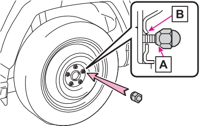
When replacing an aluminum wheel with a steel wheel, tighten the wheel nuts until the tapered portion
A comes into loose contact with
If foreign matter is on the wheel contact surface, the wheel nuts may loosen while the vehicle is in motion, causing the tire to come off.
the disc wheel seat B .
8
When replacing an aluminum wheel with an aluminum wheel, turn the
wheel nuts until the washers A
come into contact with the disc
wheel .
Tightening torque:
76 ftlbf (103 Nm, 10.5 kgfm)
Align the cutout of the wheel orna-
ment with the valve stem as shown.
|
|
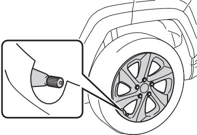
*: The wheel ornament cannot be installed on the compact spare tire.
As the compact spare tire is not equipped with a tire pressure warn- ing valve and transmitter, low infla- tion pressure of the spare tire will not be indicated by the tire pressure warning system. Also, if you replace the compact spare tire after the tire pressure warning light comes on, the light remains on.
The vehicle height may becomes lower when driving with the compact spare tire compared to when driving with standard tires.
Install the compact spare tire on one of the rear wheels of the vehicle.
 Perform the following steps and fit tire chains to the front tires:
Before storing the jack, adjust the height of the jack to match the shape of the jack holder.
The storage direction of the jack dif- fers depending on the type, so make sure to store the jack in the correct direction.
For models made in Japan*:
Except for models made in Japan*:
643
8
*: The country of production is writ- ten on the Certification Regulation label. (P.659)
645
|
The starter motor does not turn over (vehicles with smart key system) |
One of the following may be the cause of the problem:
One of the following may be the cause of the problem:
The engine starting system may be malfunctioning due to an electrical problem such as elec- tronic key battery depletion or a blown fuse. However, an interim measure is available to start the engine. (P.646)
|
The starter motor does not turn over, the interior lights and headlights do not turn on, or the horn does not sound |
One of the following may be the cause of the problem:
minals may be disconnected.
Contact your Toyota dealer if the problem cannot be repaired, or if repair procedures are unknown.
If you lose your keys
When the engine does not start, the following steps can be used as an interim measure to start the engine if the engine switch is functioning normally:
brake is set. (P.205) 
Parking brake indicator will come on.
Even if the engine can be started using the above steps, the system may be malfunction- ing. Have the vehicle inspected by your Toyota dealer.
following operations.
647
|
|
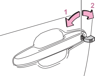
Turning the key rearward unlocks the driver’s door. Turning the key once again within 5 seconds unlocks the other doors.
roof*1 (turn and hold)*2 8
*1: If equipped
*2: These settings must be custom- ized at your Toyota dealer.
|
|
|
When using the mechanical key and operating the power windows or the moon roof (if equipped) or panoramic moon roof (if equipped)
Operate the power window or the moon roof or panoramic moon roof after checking to make sure that there is no possibility of any passenger having any of their body parts caught in the window or the moon roof or panoramic moon roof. Also, do not allow chil- dren to operate the mechanical key. It is possible for children and other passengers to get caught in the power window or the moon roof or panoramic moon roof. |
 WARNING
When the electronic key is detected, a buzzer sounds and the engine switch will turn to ON.
When the smart key system is deactivated in customization set- ting, the engine switch will turn to ACC.
is displayed on the multi- information display.
In the event that the engine still cannot be started, contact your Toyota dealer.
Shift the shift lever to P and press the engine switch as you normally do when stopping the engine.
As the above procedure is a tempo- rary measure, it is recommended that the electronic key battery be replaced immediately when the bat- tery is depleted. (P.594)
Using the mechanical key to lock the doors will not set the alarm sys- tem.
If a door is unlocked using the mechanical key when the alarm sys- tem is set, the alarm may be trig- gered. (P.73)
Release the brake pedal and press the engine switch in step 3 above. The engine does not start and modes will be changed each time the switch is pressed. (P.199)
by following the steps below.
649
When connecting the jumper (or booster) cables, depending on the situation, the alarm may activate and the doors locked. (P.74)
|
Restarting the engine |
2 Open the hood. (P.563)
on your vehicle and
connect the clamp on the other end of the positive cable to B on
the second vehicle. Then, connect a negative cable clamp to C
on the second vehicle and connect the clamp at the other end of
the negative cable to D .
8
Negative (-) battery terminal (second vehicle)
Solid, stationary, unpainted metallic point away from the battery and any moving parts as shown in the illustration
Vehicles with smart key sys- tem: Maintain the engine speed of the second vehicle and start the engine of your vehicle by turning the engine switch to ON.
Once the engine starts, have the vehicle inspected at your Toyota dealer as soon as possible.
The engine cannot be started by
push-starting.
(Vehicles with Stop & Start system: Except when the engine is stopped due to the Stop & Start system)
When the battery terminals are removed, the information stored in the ECU is cleared. Before remov- ing the battery terminals, contact your Toyota dealer.
The electricity stored in the battery will discharge gradually even when the vehicle is not in use, due to nat- ural discharge and the draining effects of certain electrical appli- ances. If the vehicle is left for a long time, the battery may discharge, and the engine may be unable to start. (The battery recharges auto- matically during driving.)
651
sible to unlock the doors using the smart key system when the bat- tery is discharged. Use the wire- less remote control or the mechanical key to lock or unlock the doors.
After the battery terminals have been disconnected and recon- nected or the battery has been replaced, the Stop & Start system may not automatically stop the engine for approximately 5 to 60 minutes.
Use a genuine battery specifically designed for use with the Stop & Start system or a battery with equiv- alent specifications to a genuine battery. If an unsupported battery is used, Stop & Start system functions may be restricted to protect the bat- tery. Also, battery performance may decrease and the engine may not be able to restart. Contact your Toy- ota dealer for details.
Use a battery that the case size is
same as the previous one (LN3), 20 hours rate capacity (20HR) is equiv- alent (65Ah) or greater, and perfor- mance rating (CCA) is equivalent (603A) or greater.
Type B:
Use a battery that the case size is same as the previous one (LN2), 20 hours rate capacity (20HR) is equiv- alent (60Ah) or greater, and perfor- mance rating (CCA) is equivalent (560A) or greater.
Type C:
Use a battery that the case size is same as the previous one (LN2), 20 hours rate capacity (20HR) is equiv- alent (60Ah) or greater, and perfor- mance rating (CCA) is equivalent (563A) or greater.

8
8-2. Steps to take in an emergency
653
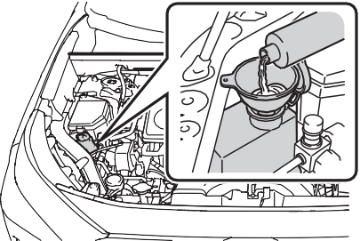
If a large amount of coolant leaks, immediately contact your Toyota dealer.
|
|
|
Correction procedures |
If you do not see steam: Carefully lift the hood.
8
A Reservoir B “FULL” line C “LOW” line
5 Add coolant if necessary.
Water can be used in an emer-
gency if coolant is unavailable.
|
|
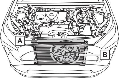
 The fan operate when the air condi- tioning system is turned on immedi- ately after a cold start. Confirm that the fan is operating by checking the fan sound and air flow. If it is diffi- cult to check these, turn the air con- ditioning system on and off repeatedly. (The fan may not oper- ate in freezing temperatures.)
If the fan is operating:
Have the vehicle inspected at the nearest Toyota dealer.
If the message does not disappear: Stop the engine and contact your Toyota dealer.
If the message is not displayed: Have the vehicle inspected at the nearest Toyota dealer.
655
|
Recovering procedure |
other material to help provide  traction under the tires.
8
Press to turn off TRAC. (P.363)
Vehicle specifications 9
9-3. Initialization
Items to initialize 693
9
Download Manual