RAMBOX — IF EQUIPPED
The RamBox system is an integrated pickup box storage and cargo management system consisting of three features:
NOTE:
Bed rail tie-down system is also available for vehicles not equipped with a RamBox.
Cargo storage bins are located on both sides of the pickup box. The cargo storage bins provide watertight, lockable, illuminated storage for up to 150 lbs (68 kg) of evenly distrib- uted cargo.
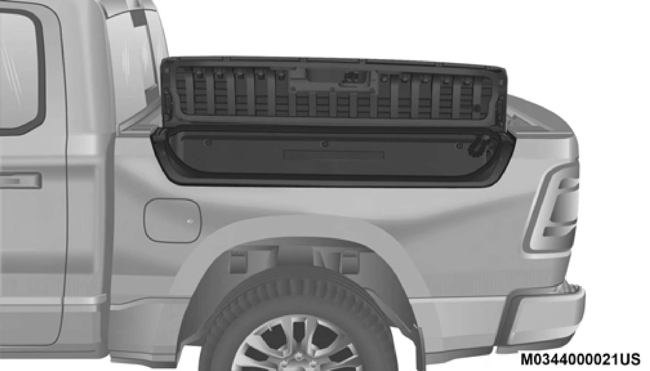
RamBox Cargo Storage Bins
2
To open a storage bin with the RamBox unlocked, push and release the button located on the lid. The RamBox lid will open upward to allow hand access. Lift the lid to fully open.
NOTE:
RamBox will not open when the pushbutton is pushed if the RamBox is locked.
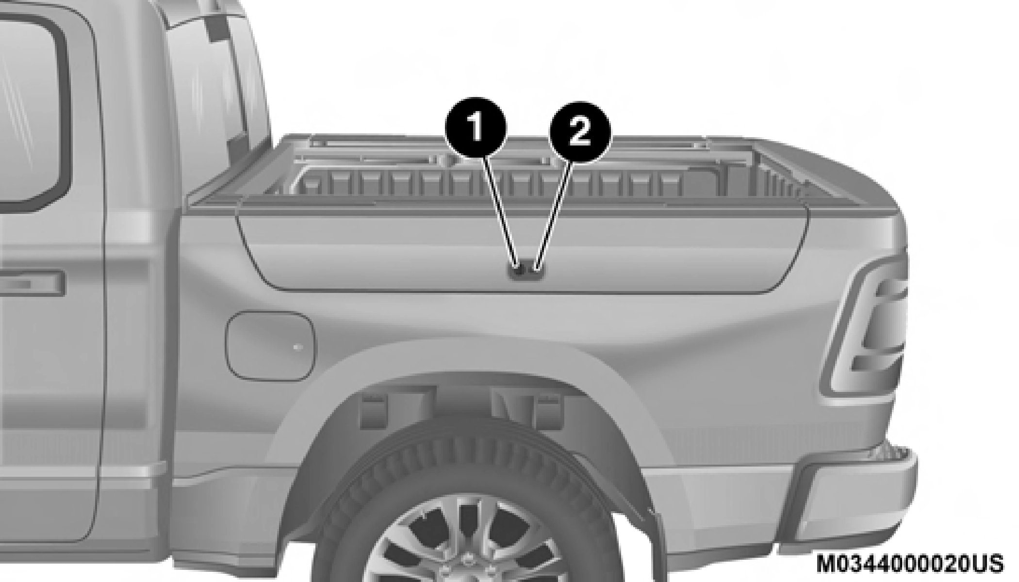
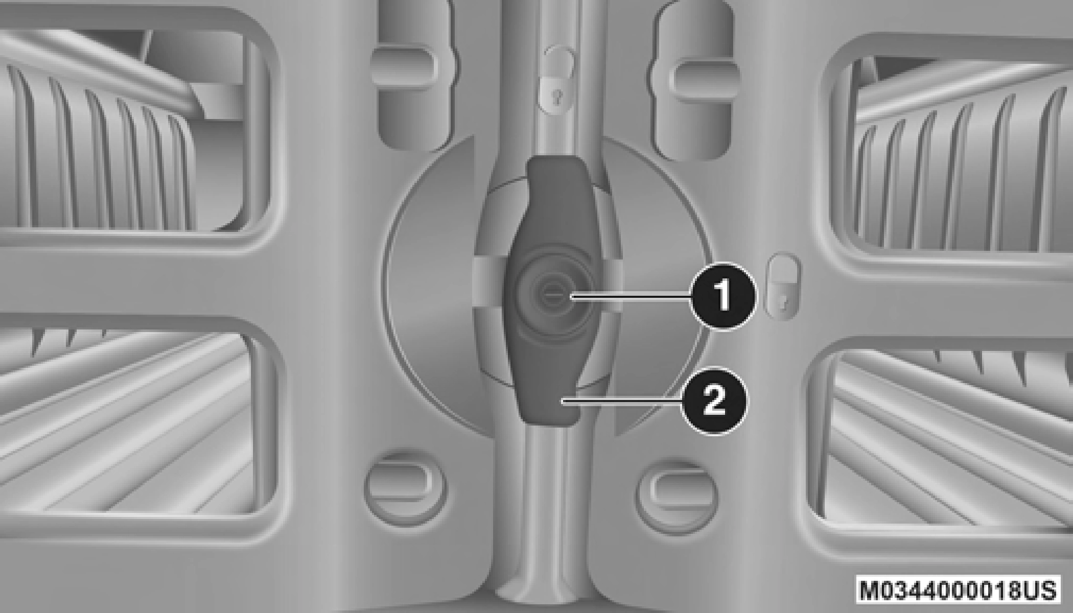
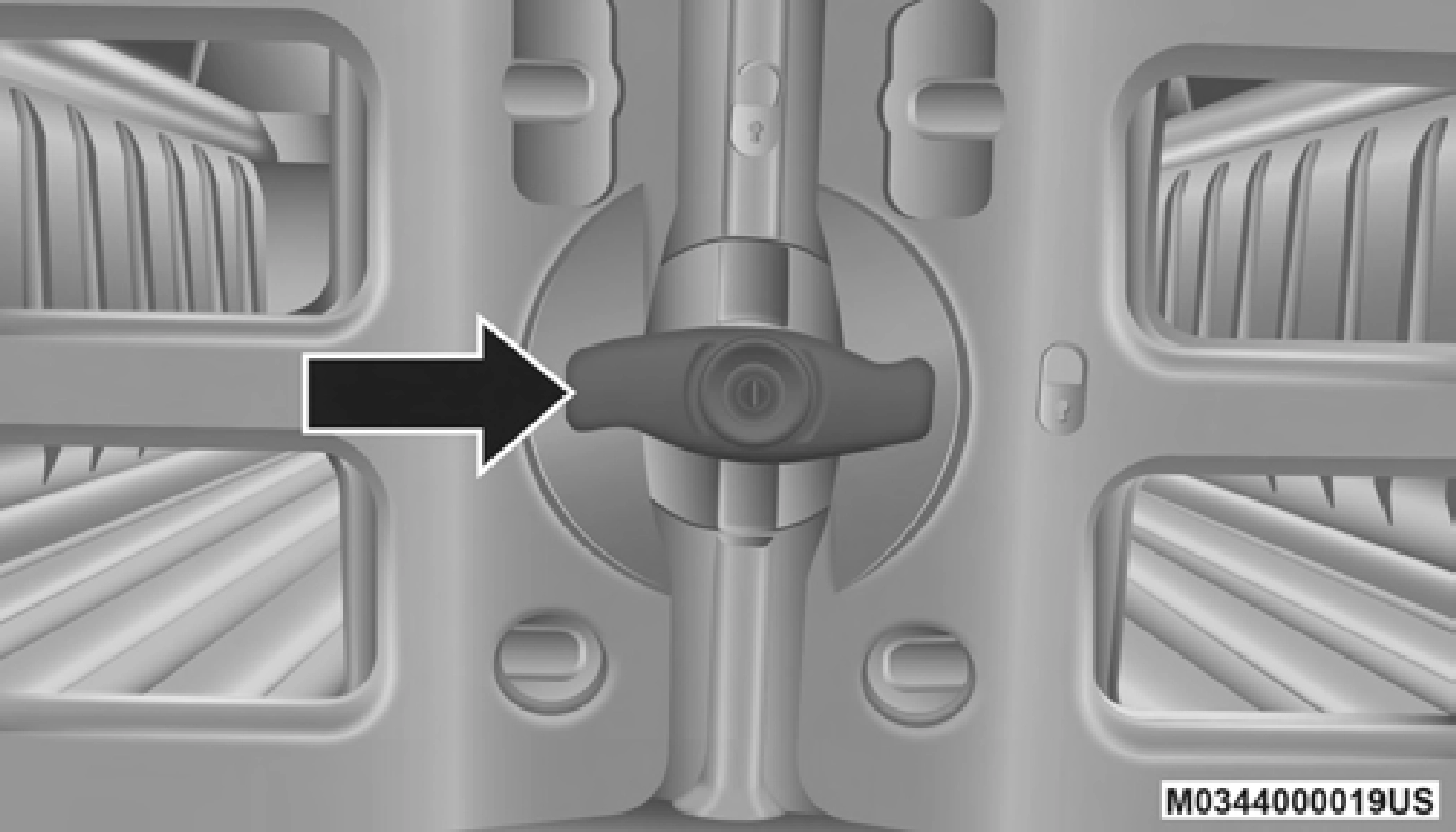
RamBox Push Button And Keyhole Lock
1 — Keyhole Lock 2 — Push Button
The interior of the RamBox will automatically illuminate when the lid is opened. The timing can be adjusted through your touchscreen.
Refer to “Uconnect Settings” in “Multimedia” for further information.
Cargo bins feature two removable drain plugs (to allow water to drain from bins). To remove plug, pull up on the edge. To install push plug downward into drain hole.
If equipped, a power inverter can be found inside the RamBox.
Refer to “Electrical Power Outlets” in this chapter for further information.
NOTE:
Provisions are provided in the bins for cargo dividers. These accessories (in addition to other RamBox accessories) are available from Mopar.
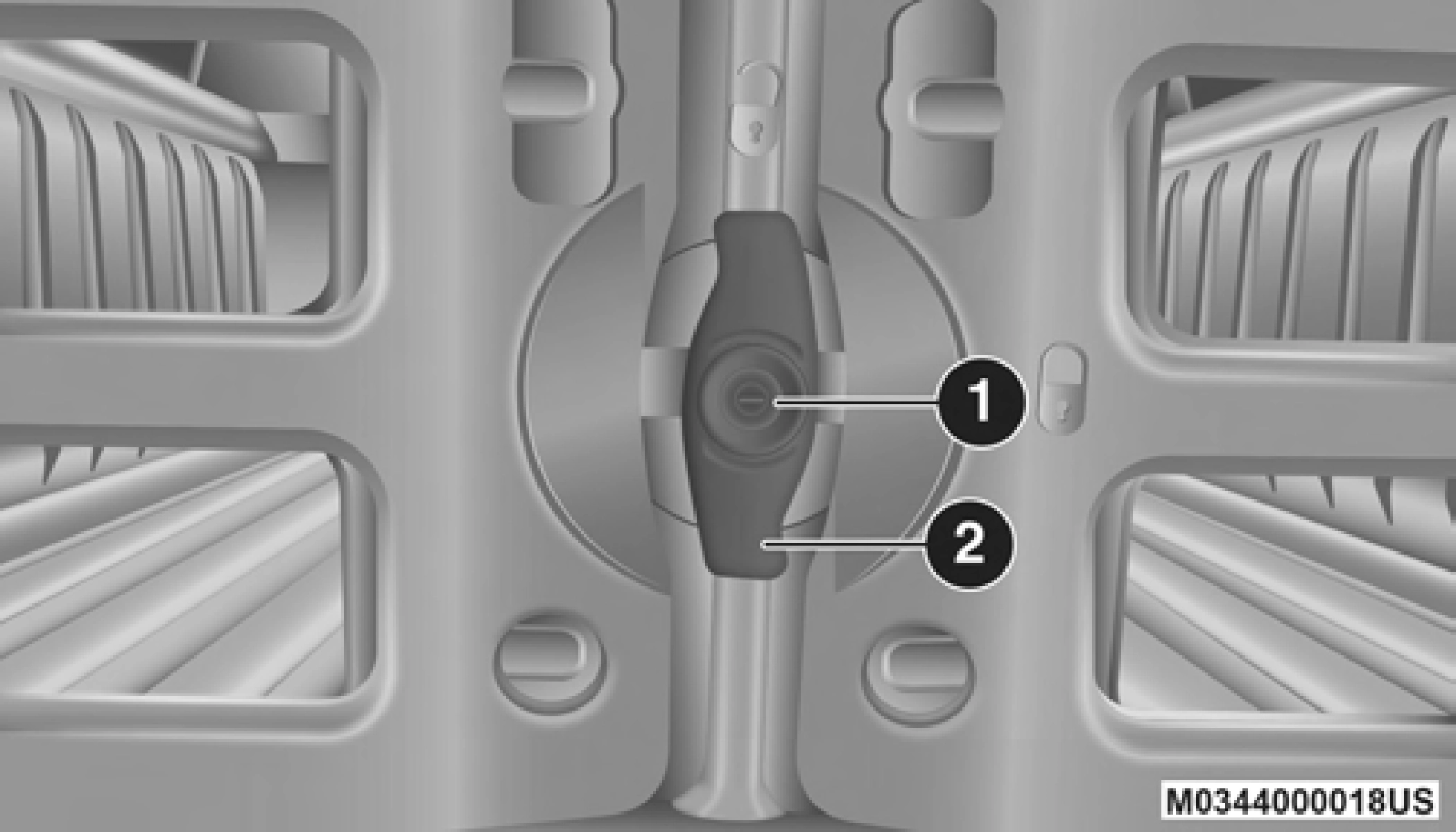
Push and release the lock or unlock button on the key fob to lock and unlock all doors, the tailgate and the RamBox (if equipped). Refer to “Keys” in this chapter for further details. To unlatch the storage bin manually, insert the emergency key into the keyhole and turn clockwise. Always return the key to the upright (vertical) position before removing it from the keyhole.
Carefully follow these warnings to help prevent personal injury or damage to your vehicle:
2
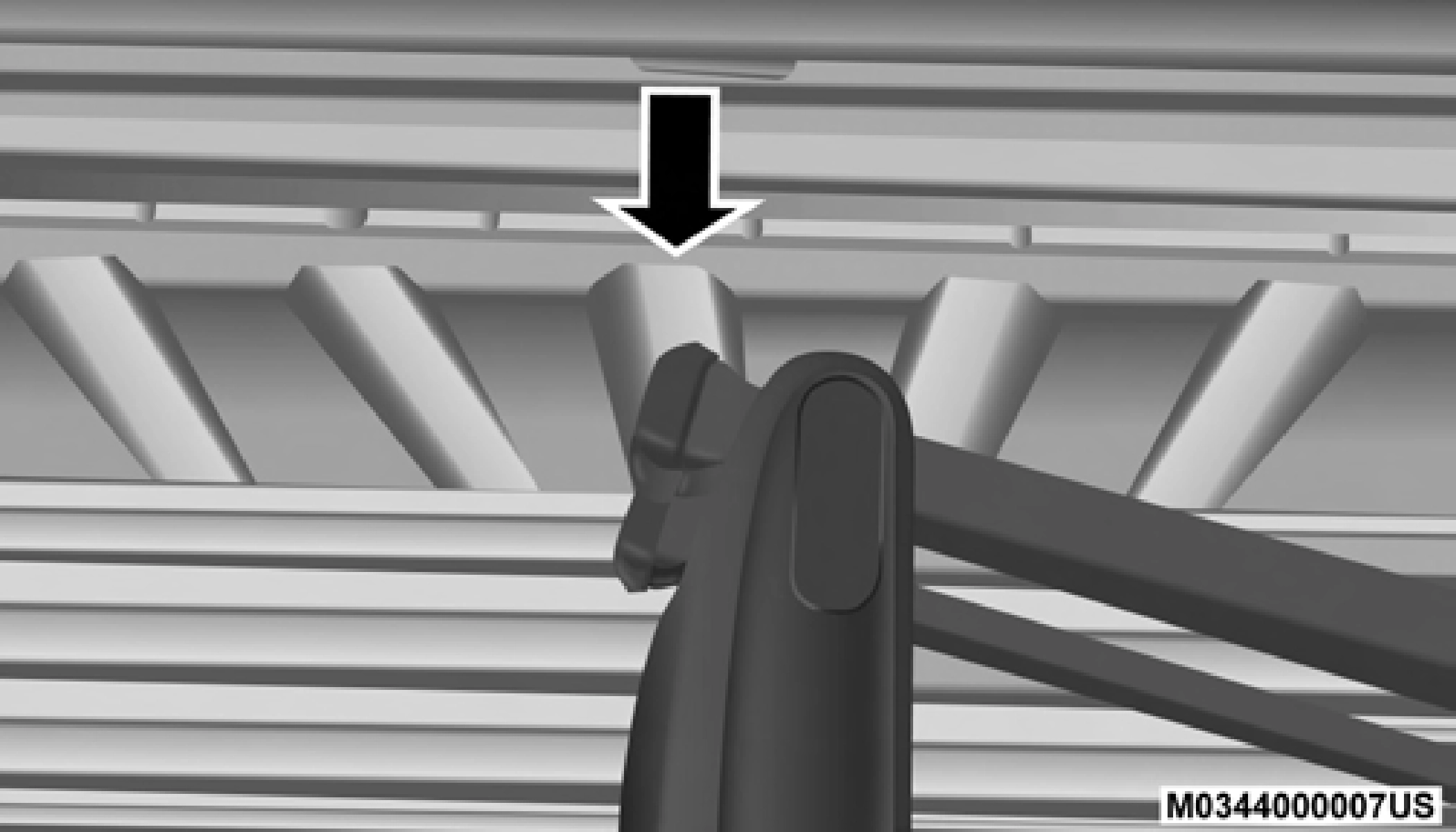
As a security measure, a Storage Bin Cover Emergency Release is built into the storage bin cover latching mecha- nism.
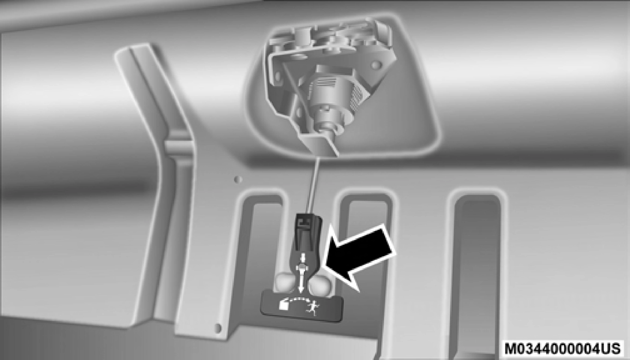
Storage Bin Cover Emergency Release Lever
NOTE:
In the event of an individual being locked inside the storage bin, the storage bin cover can be opened from inside of the bin by pulling on the glow-in-the-dark lever attached to the storage bin cover latching mechanism.
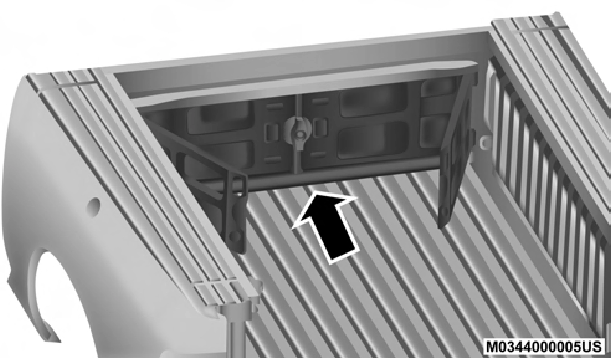
The bed divider has two functional positions:
The storage position for the bed divider is at the front of the truck bed which maximizes the bed cargo area when not in use.
To install the bed divider into the storage position, perform the following:
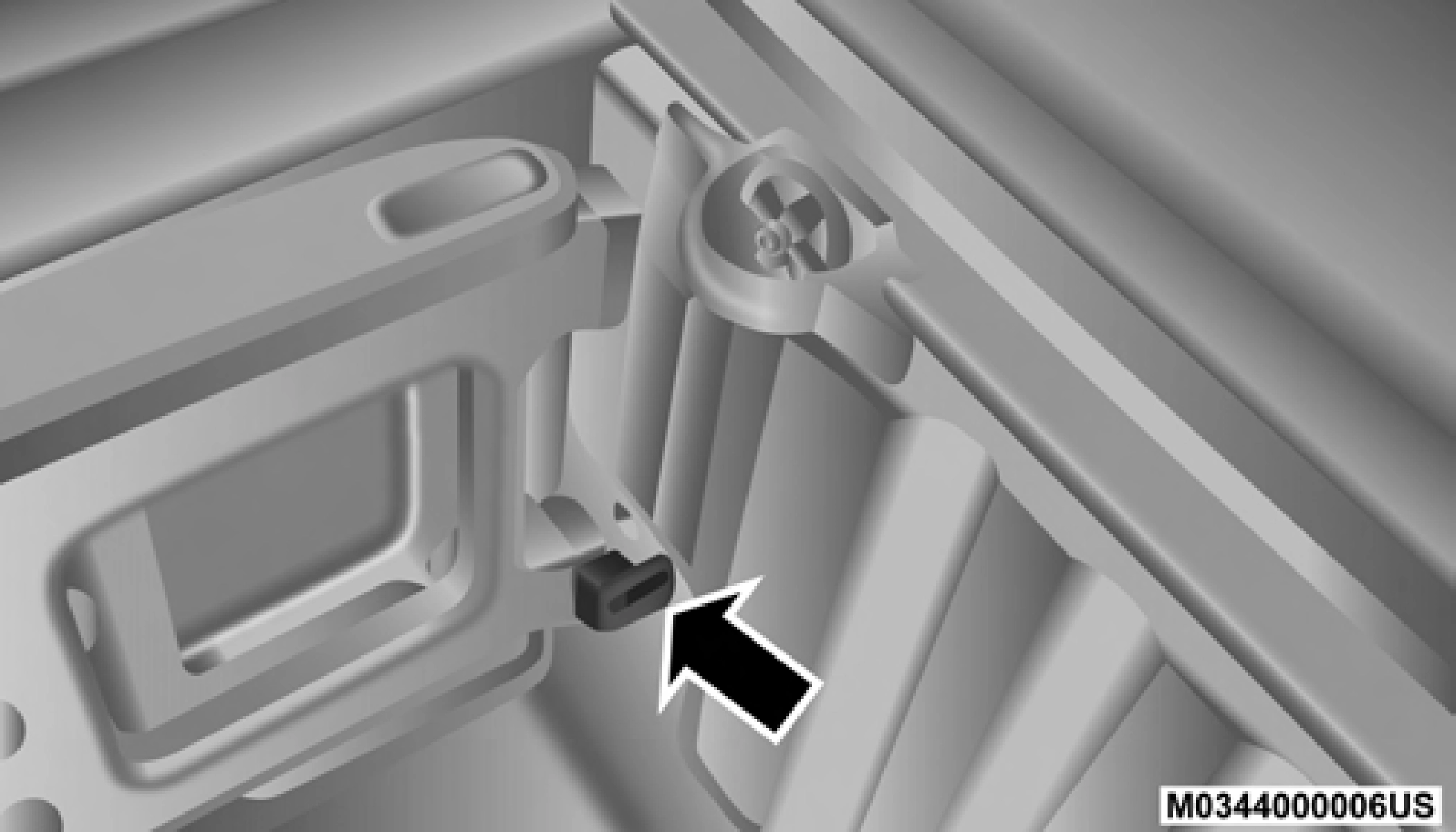
Center Handle And Lock
1 — Center Handle Lock 2 — Handle
 2
2
Storage Position
Cargo Tie Down Loop

Side Gates Closed
The divider position is intended for managing your cargo and assisting in keeping cargo from moving around the bed. There are 11 divider slots along the bed inner panels which allow for various positions to assist in managing your cargo.
To install the bed divider into a divider position, perform the following:
2
 Center Handle And Lock
1 — Center Handle Lock 2 — Handle
Aligning Gate To Slots
Side Gates Closed
NOTE:
This feature is available for vehicles both equipped, or not equipped, with a RamBox.
There are two adjustable cleats on each side of the bed that can be used to assist in securing cargo.
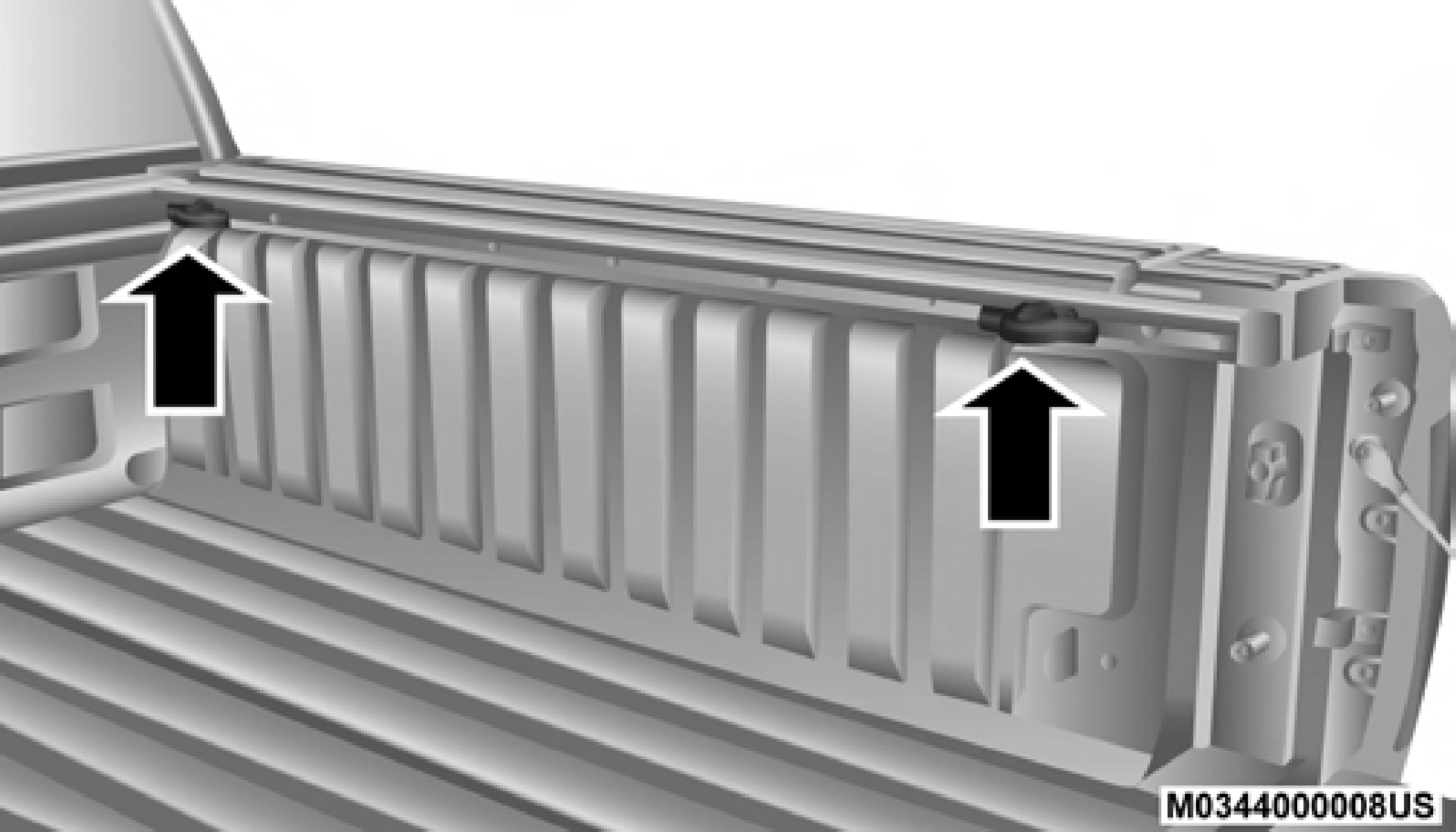
Adjustable Cleats
Each cleat must be located and tightened down in one of the detents, along either rail, in order to keep cargo properly secure.
To move the cleat to any position on the rail, turn the nut counterclockwise, approximately three turns. Then pull out on the cleat and slide it to the detent nearest the desired loca- tion. Make sure the cleat is seated in the detent and tighten
the nut. 2
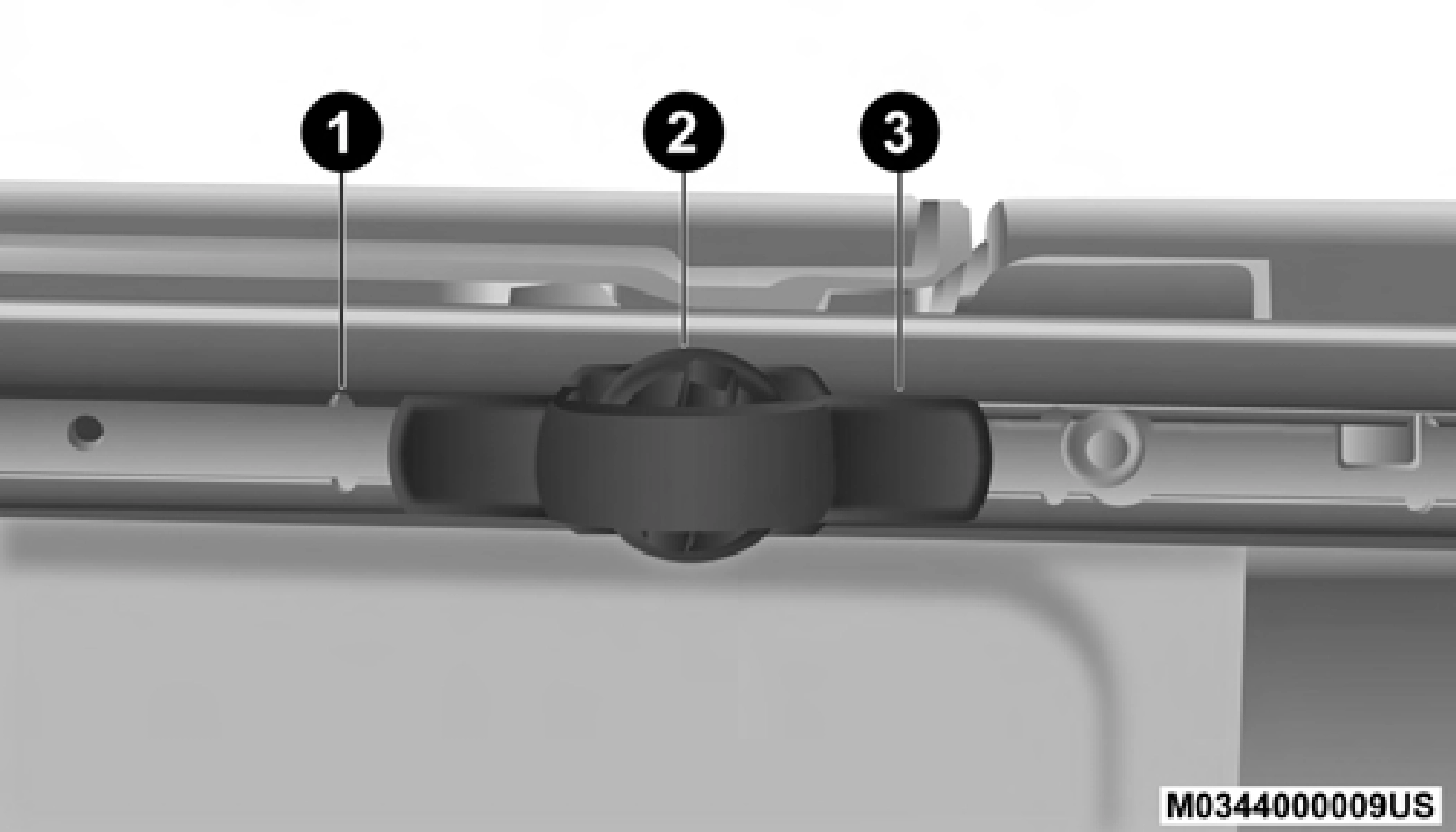
Adjustable Cleat Assembly
1 — Utility Rail Detent 2 — Cleat Retainer Nut 3 — Utility Rail Cleat
Cleat Removal (Standard Box Rail)
To remove the cleats from the utility rail, slide the cleat forward to access the cut out at the end of the box rail, then remove the cleat.
Cleat Removal (With Tonneau Cover)
To remove the cleats from the utility rail, remove the end cap screw located in the center of the end cap, using a #T30 Torx head driver. Remove the end cap and slide the cleat off the end of the rail.
Cleat Removal (Without Tonneau Cover)
To remove the cleats from the utility rail, depress the clip at the bottom of the rear end cap and slide the cap off of the rail. Once the cap is removed, slide the cleat out.
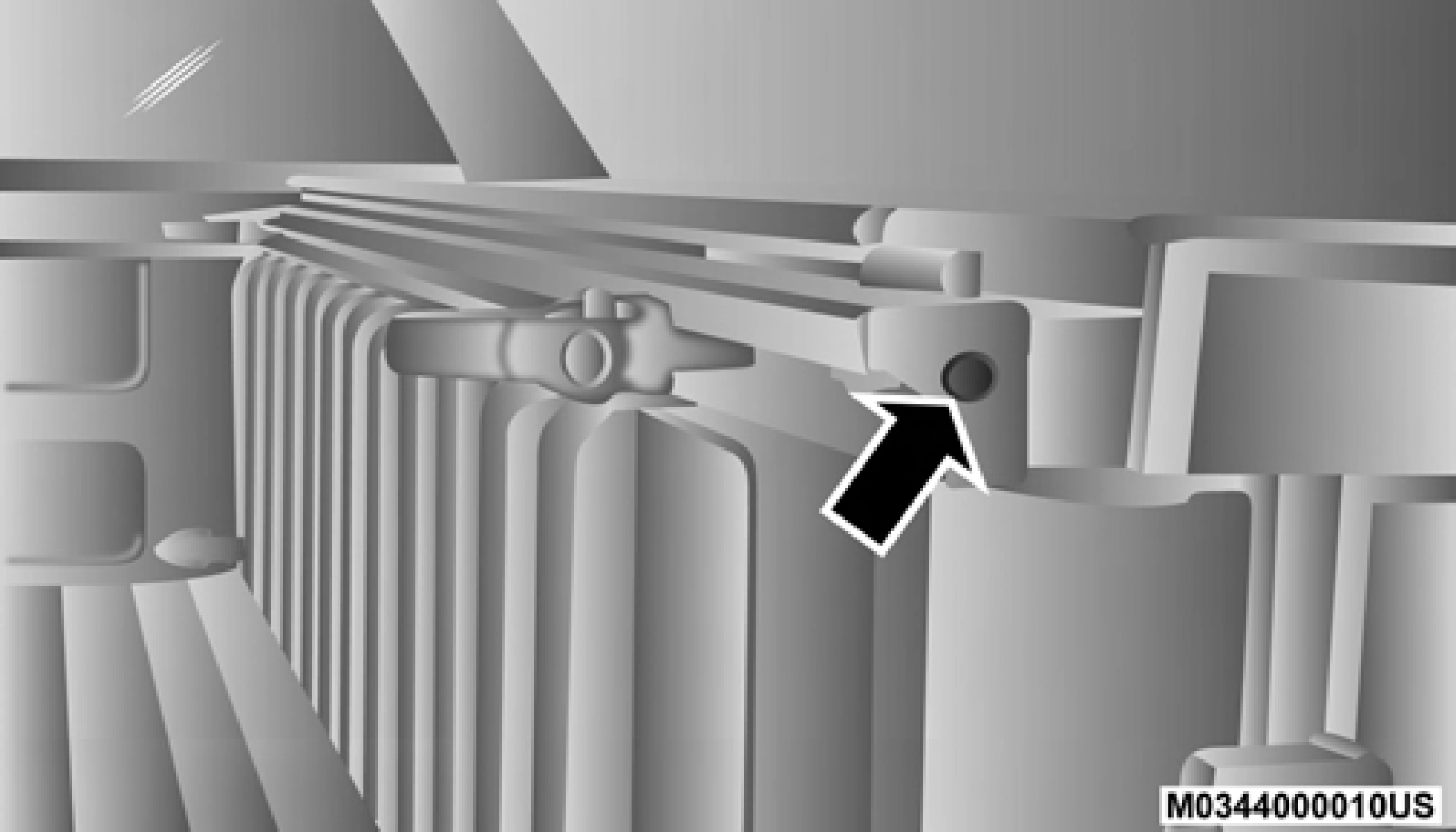
Utility Rail End Cap
Download Manual