VEHICLE LOADING
Gross Vehicle Weight Rating (GVWR)
The Gross Vehicle Weight Rating (GVWR) is the total permissible weight of your vehicle including driver, passen- 5 gers, vehicle, options and cargo. The label also specifies maximum capacities of front and rear axle systems Gross
Axle Weight Rating (GAWR). Total load must be limited so GVWR and front and rear GAWR are not exceeded.
The payload of a vehicle is defined as the allowable load weight a truck can carry, including the weight of the driver, all passengers, options and cargo.
The GAWR is the maximum permissible load on the front and rear axles. The load must be distributed in the cargo area so that the GAWR of each axle is not exceeded.
Each axle GAWR is determined by the components in the system with the lowest load carrying capacity (axle, springs, tires or wheels). Heavier axles or suspension components sometimes specified by purchasers for increased durability does not necessarily increase the vehicle's GVWR.
The tire size on the Vehicle Certification Label represents the actual tire size on your vehicle. Replacement tires must be equal to the load capacity of this tire size.
This is the rim size that is appropriate for the tire size listed.
This is the cold tire inflation pressure for your vehicle for all loading conditions up to full Gross Axle Weight Rating (GAWR).
The curb weight of a vehicle is defined as the total weight of the vehicle with all fluids, including vehicle fuel, at full capacity conditions, and with no occupants or cargo loaded into the vehicle. The front and rear curb weight values are determined by weighing your vehicle on a commercial scale before any occupants or cargo are added.
The actual total weight and the weight of the front and rear of your vehicle at the ground can best be determined by weighing it when it is loaded and ready for operation.
The entire vehicle should first be weighed on a commercial scale to insure that the Gross Vehicle Weight Rating (GVWR) has not been exceeded. The weight on the front and rear of the vehicle should then be determined separately to be sure that the load is properly distributed over the front and rear axle. Weighing the vehicle may show that the Gross Axle Weight Rating (GAWR) of either the front or rear axles has been exceeded but the total load is within the specified GVWR. If so, weight must be shifted from front to rear or rear to front as appropriate until the specified weight limita- tions are met. Store the heavier items down low and be sure
that the weight is distributed equally. Stow all loose items securely before driving.
Improper weight distributions can have an adverse effect on the way your vehicle steers and handles and the way the brakes operate.
In this section you will find safety tips and information on limits to the type of towing you can reasonably do with your vehicle. Before towing a trailer, carefully review this infor- mation to tow your load as efficiently and safely as possible.
To maintain the New Vehicle Limited Warranty coverage, follow the requirements and recommendations in this manual concerning vehicles used for trailer towing.
The following trailer towing related definitions will assist you in understanding the following information:
The Gross Vehicle Weight Rating (GVWR) is the total allow- able weight of your vehicle. This includes driver, passengers, cargo and tongue weight. The total load must be limited so that you do not exceed the GVWR. Refer to “Vehicle Loading/Vehicle Certification Label” in “Starting And Operating” for further information.
The Gross Trailer Weight (GTW) is the weight of the trailer plus the weight of all cargo, consumables and equipment (permanent or temporary) loaded in or on the trailer in its “loaded and ready for operation” condition.
The recommended way to measure GTW is to put your fully loaded trailer on a vehicle scale. The entire weight of the trailer must be supported by the scale.
The Gross Combination Weight Rating (GCWR) is the total allowable weight of your vehicle and trailer when weighed in combination.
The Gross Axle Weight Rating (GAWR) is the maximum capacity of the front and rear axles. Distribute the load over the front and rear axles evenly. Make sure that you do not exceed either front or rear GAWR. Refer to “Vehicle Loading/Vehicle Certification Label” in “Starting And Operating” for further information.
The Tongue Weight (TW) is the downward force exerted on the hitch ball by the trailer. You must consider this as part of the load on your vehicle.
The frontal area is the maximum height multiplied by the maximum width of the front of a trailer.
The Trailer Sway Control (TSC) can be a mechanical tele- scoping link that can be installed between the hitch receiver and the trailer tongue that typically provides adjustable fric- tion associated with the telescoping motion to dampen any unwanted trailer swaying motions while traveling.
If equipped, the electronic TSC recognizes a swaying trailer and automatically applies individual wheel brakes and/or reduces engine power to attempt to eliminate the trailer sway.
A weight-carrying hitch supports the trailer tongue weight, just as if it were luggage located at a hitch ball or some other connecting point of the vehicle. These kinds of hitches are the most popular on the market today and they are commonly used to tow small and medium sized trailers.
A weight-distributing system works by applying leverage through spring (load) bars. They are typically used for heavier loads to distribute trailer tongue weight to the tow vehicle's front axle and the trailer axle(s). When used in accordance with the manufacturer's directions, it provides for a more level ride, offering more consistent steering and brake control, thereby enhancing towing safety. The addi- tion of a friction/hydraulic sway control also dampens sway caused by traffic and crosswinds and contributes positively to tow vehicle and trailer stability. Trailer sway control and a weight distributing (load equalizing) hitch are recom- mended for heavier Tongue Weights (TW) and may be required depending on vehicle and trailer configuration/ loading to comply with GAWR requirements.
5
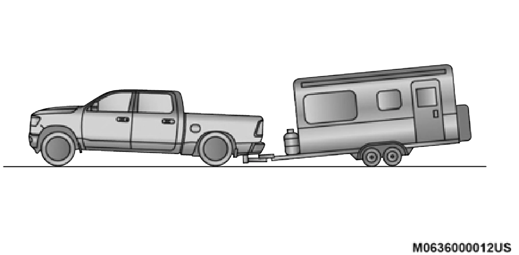
Without Weight-Distributing Hitch (Incorrect)
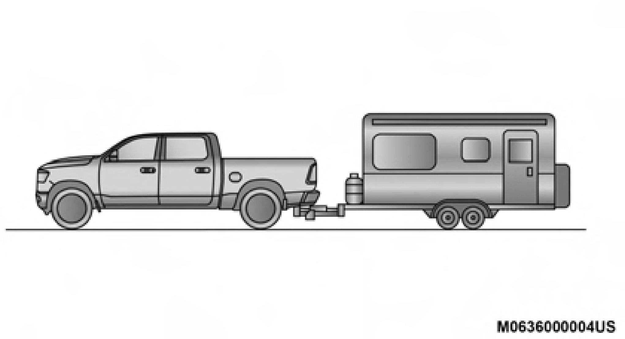
With Weight-Distributing Hitch (Correct)
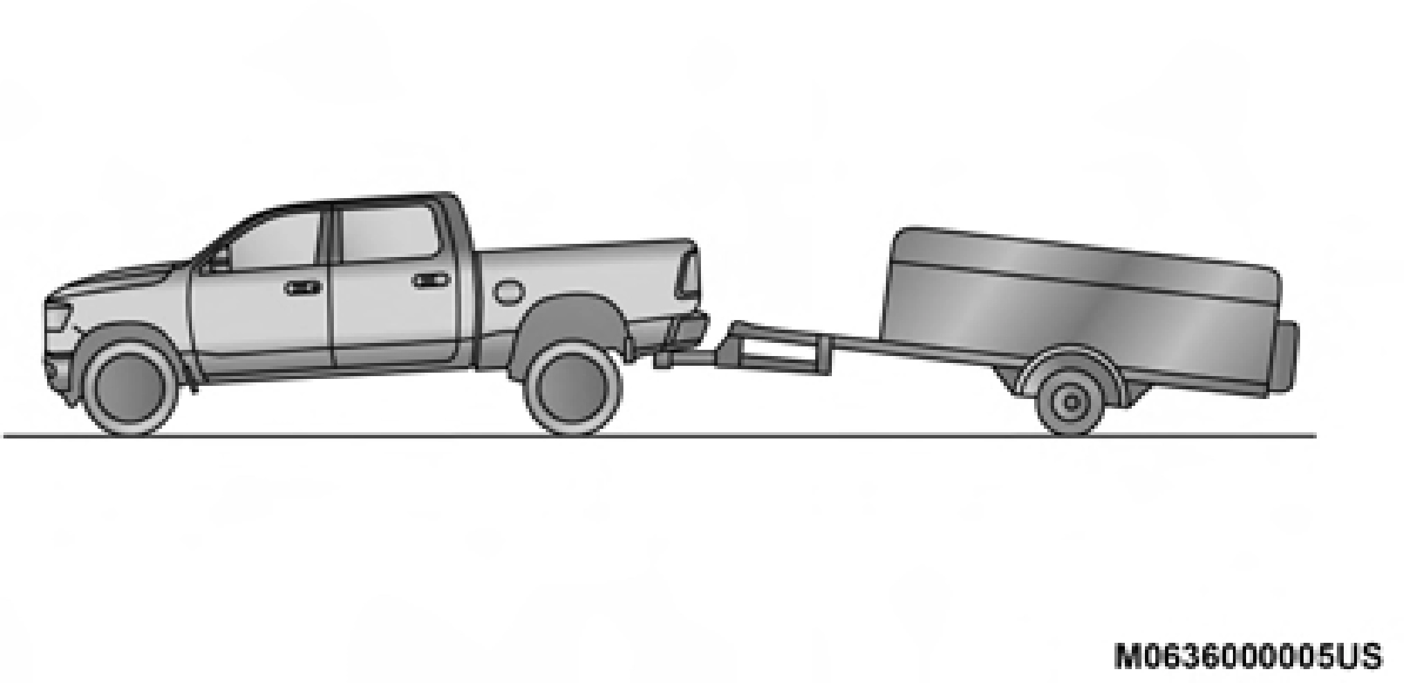
Improper Adjustment Of Weight-Distributing Hitch (Incorrect)
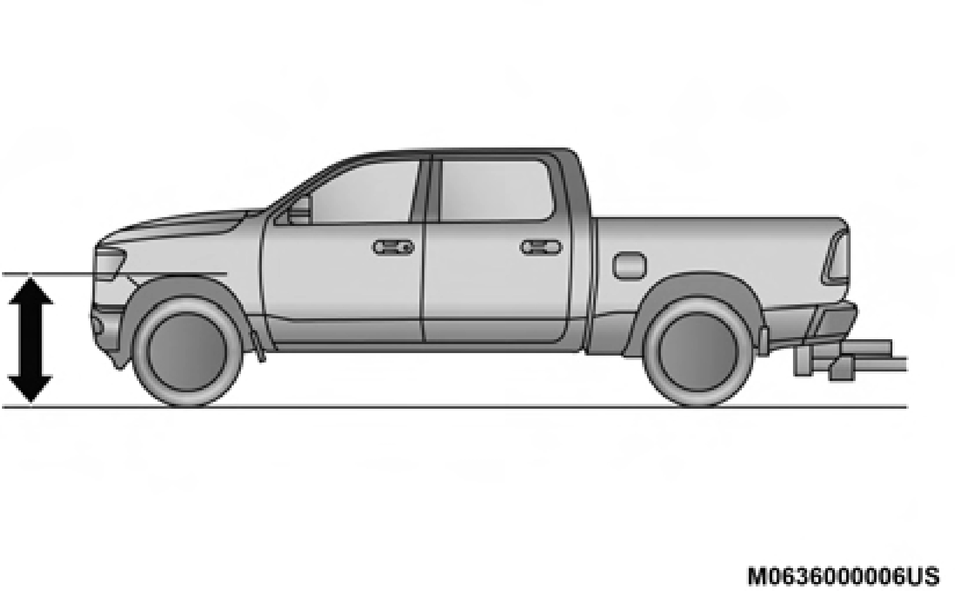
Recommended Distribution Hitch Adjustment Towing With 1500 Air Suspension
NOTE:
The vehicle must remain in the engine run position with all doors closed while attaching a trailer for proper leveling of the air suspension system.
 Use the instrument cluster or touch screen radio settings and switch off tire jack mode. Make sure the truck returns to normal ride height. Preform a visual inspection of the trailer and weight distributing hitch to confirm manufac- turers' recommendations have been met.
Measuring Height (H)
5
NOTE:
For all towing conditions, we recommend towing with tow haul mode engaged.
The following chart provides the maximum trailer weight a given factory equipped trailer hitch type can tow and should be used to assist you in selecting the correct trailer hitch for your intended towing condition.
|
Trailer Hitch Type and Maximum Trailer Weight |
|
|
Hitch Type |
Max. Trailer Weight / Max. Tongue Weight |
|
Class III Bumper Hitch - 1500 Model |
5,000 lbs (2,268 kg) / 500 lbs (226 kg) |
|
Class IV - 1500 Model |
12,750 lbs (5,783 kg) / 1,275 lbs (578 kg) |
|
Refer to the “Trailer Towing Weights (Maximum Trailer Weight Ratings)” for the Maximum Gross Trailer Weight (GTW) towable for your given drivetrain. |
All trailer hitches should be professionally installed on your vehicle.
Class III Bumper Hitch Access
Remove the cap with a trim stick or screw driver to access the Class III hitch attachment.
NOTE:
Be careful not to scratch the bumper step pad.
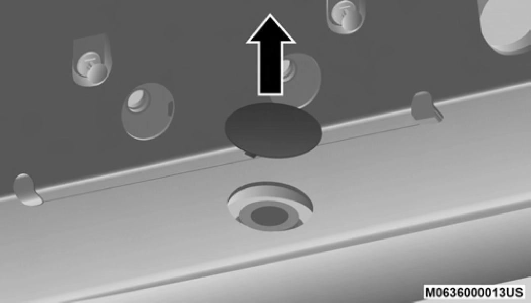
Class III Bumper Hitch Access
NOTE:
For trailer towing information (maximum trailer weight ratings) refer to the following website addresses:
Consider the following items when computing the weight on the rear axle of the vehicle:
NOTE:
Remember that everything put into or on the trailer adds to
the load on your vehicle. Also, additional factory-installed
options or dealer-installed options must be considered as 5 part of the total load on your vehicle. Refer to the “Tire And Loading Information” placard for the maximum combined
weight of occupants and cargo for your vehicle.
To promote proper break-in of your new vehicle drivetrain components, the following guidelines are recommended.
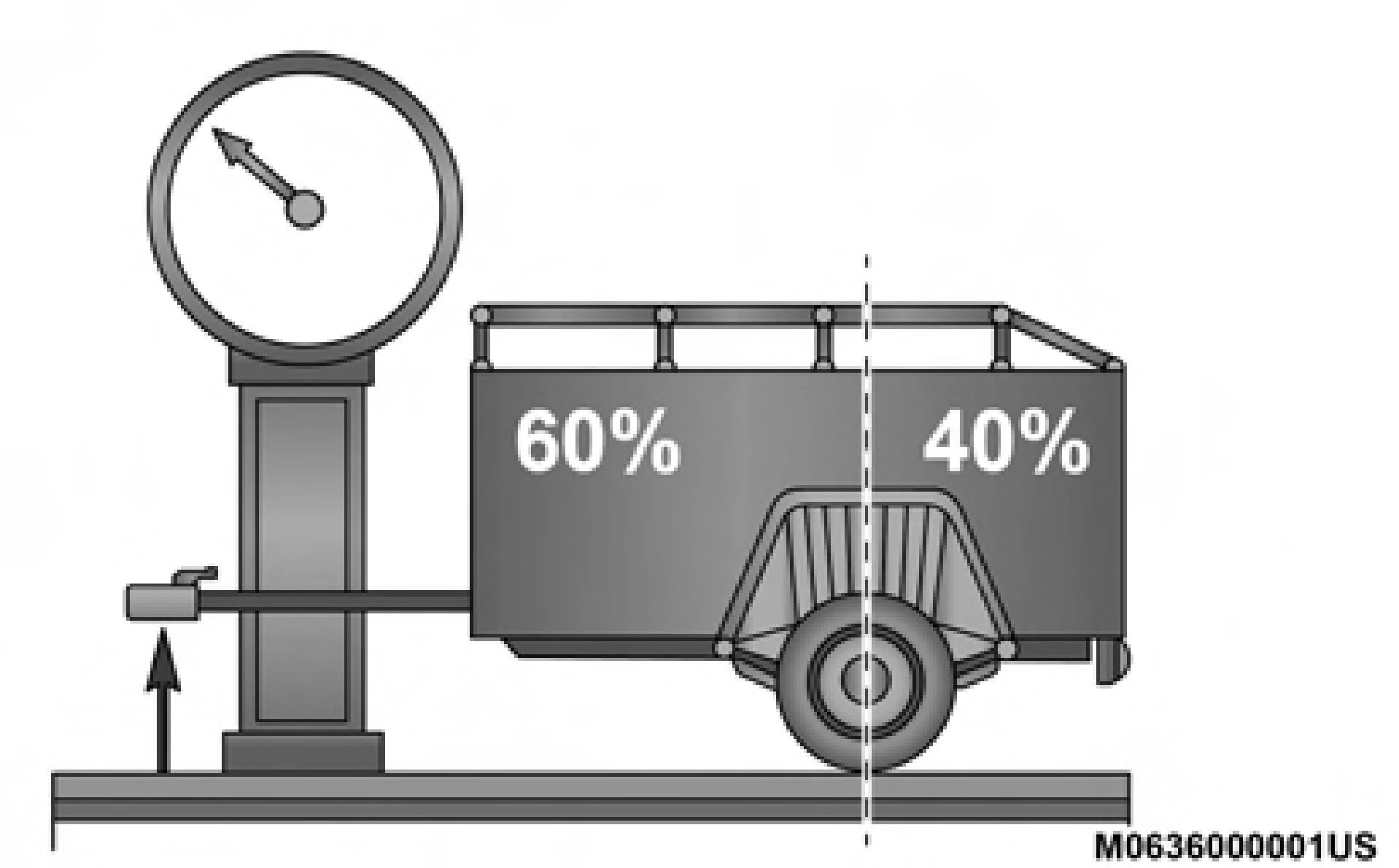 Weight Distribution
(Continued)
Perform the maintenance listed in the “Scheduled Servicing”. Refer to “Scheduled Servicing” in “Servicing And Maintenance” for the proper maintenance intervals. When towing a trailer, never exceed the GAWR or GCWR ratings.
WARNING! (Continued)
(Continued)
5
Your vehicle may have an Integrated Trailer Brake Module (ITBM) for Electric and Electric Over Hydraulic (EOH) trailer brakes.
NOTE:
This module has been designed and verified with electric trailer brakes and new electric over hydraulic systems. Some previous EOH systems may not be compatible with ITBM.
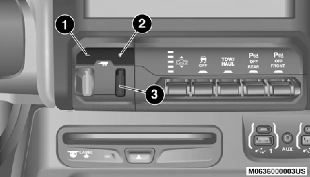
Integrated Trailer Brake Module (ITBM)
1 — GAIN Adjustment Button 2 — GAIN Adjustment Button
3 — Manual Brake Control Lever
The user interface consists of the following:
Manual Brake Control Lever
Slide the manual brake control lever to the left to activate power to the trailer's electric brakes independent of the tow vehicle's brakes. If the manual brake control lever is acti- vated while the brake is also applied, the greater of the two inputs determines the power sent to the trailer brakes.
The trailer and the vehicle's stop lamps will come on when braking normally with the vehicle brake pedal. Only the trailer stop lamps will come on when the manual brake control lever is applied.
Trailer Brake Status Indicator Light
This light indicates the trailer electrical connection status.
If no electrical connection is detected after the ignition is turned on, pushing the GAIN adjustment button or sliding the manual brake control lever will display the GAIN setting for 10 seconds and the “Trailer Brake Status Indicator Light” will not be displayed.
If a fault is detected in the trailer wiring or the Integrated Trailer Brake Module (ITBM), the “Trailer Brake Status Indi- cator Light” will flash.
GAIN Adjustment Buttons (+/-)
Pushing these buttons will adjust the brake control power output to the trailer brakes in 0.5 increments. The GAIN setting can be increased to a maximum of 10 or decreased to a minimum of 0 (no trailer braking).
GAIN
The GAIN setting is used to set the trailer brake control for the specific towing condition and should be changed as towing conditions change. Changes to towing conditions include trailer load, vehicle load, road conditions and weather.
Adjusting GAIN NOTE:
This should only be performed in a traffic free environment at speeds of approximately 20–25 mph (30–40 km/h).
nized by the ITBM, braking functions will not be avail- able), the GAIN setting will illuminate and the correct type of trailer must be selected from the instrument cluster display options.
Type appears on the screen. 5
Repeat steps 8 and 9 until the GAIN setting is at a point just below trailer wheel lockup. If towing a heavier trailer, trailer wheel lockup may not be attainable even with the maximum GAIN setting of 10.
|
Light Electric |
Heavy Electric |
Light EOH |
Heavy EOH |
|
|
Type of Trailer Brakes |
Electric Trailer Brakes |
Electric Trailer Brakes |
Electric over Hydraulic Trailer Brakes |
Electric over Hydraulic Trailer Brakes |
|
Load |
*Under 10,000 lbs |
*Above 10,000 lbs |
*Under 10,000 lbs |
*Above 10,000 lbs |
*The suggested selection depends and may change depending on the customer preferences for braking perfor- mance. Condition of the trailer brakes, driving and road state may also affect the selection.
Display Messages
The trailer brake control interacts with the instrument cluster display. Display messages, along with a single chime, will be displayed when a malfunction is determined in the trailer connection, trailer brake control, or on the trailer. Refer to “Instrument Cluster Display” in “Getting To Know Your Instrument Panel” for further information.
NOTE:
Whenever you pull a trailer, regardless of the trailer size, stoplights and turn signals on the trailer are required for motoring safety.
The Trailer Tow Package may include a four- and seven-pin wiring harness. Use a factory approved trailer harness and connector.
NOTE:
Do not cut or splice wiring into the vehicle's wiring harness.
The electrical connections are all complete to the vehicle but you must mate the harness to a trailer connector. Refer to the following illustrations.
NOTE:
1 — Female Pins 2 — Male Pin
5
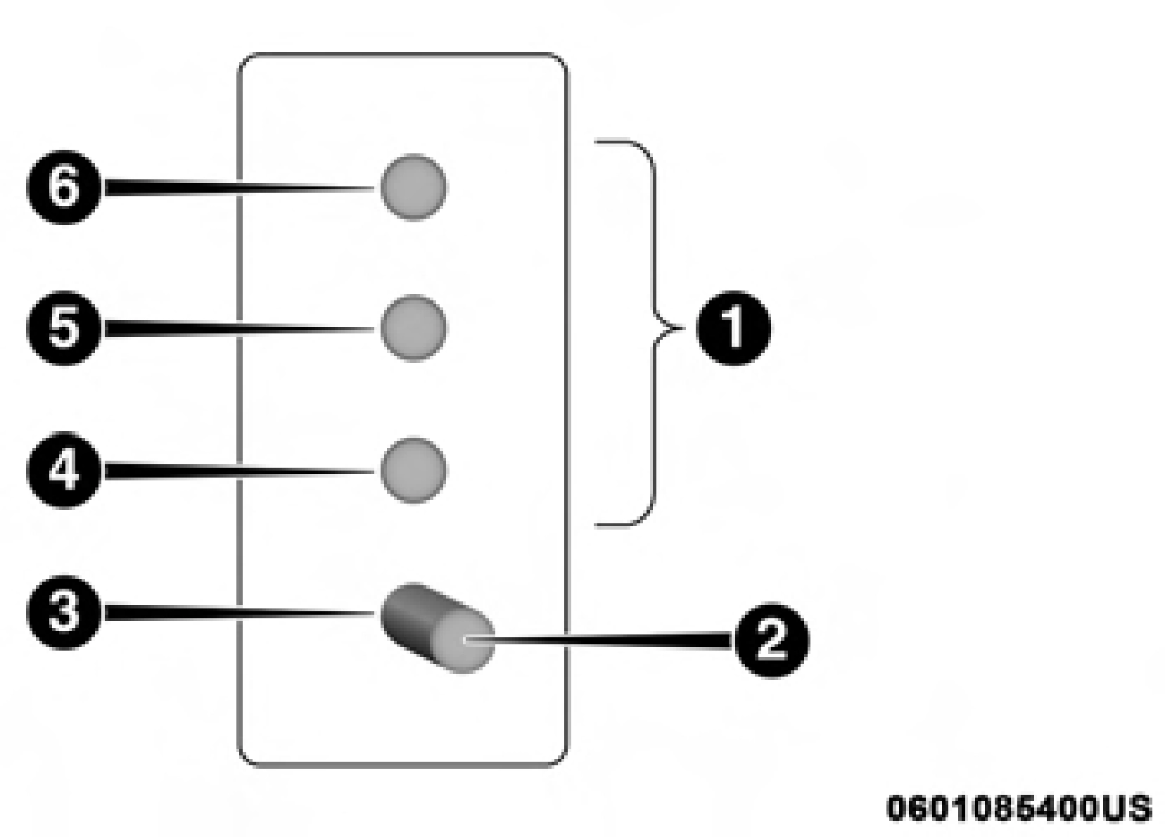 Four-Pin Connector
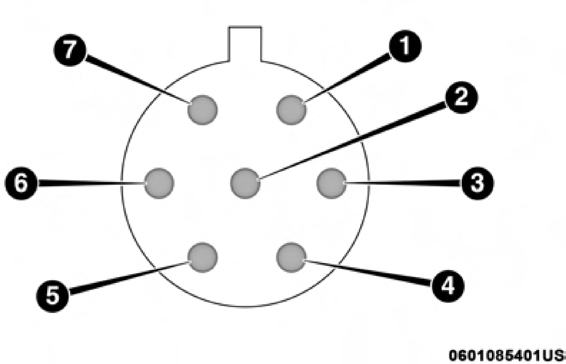 Seven-Pin Connector
Before setting out on a trip, practice turning, stopping, and backing up the trailer in an area located away from heavy traffic.
The DRIVE range can be selected when towing. The trans- mission controls include a drive strategy to avoid frequent shifting when towing. However, if frequent shifting does occur while in DRIVE, select TOW/HAUL mode or select a lower gear range (using the Electronic Range Select (ERS) shift control).
NOTE:
Using TOW/HAUL mode or selecting a lower gear range (using the ERS shift control) while operating the vehicle under heavy loading conditions will improve performance and extend transmission life by reducing excessive shifting and heat build up. This action will also provide better engine braking.
To reduce potential for automatic transmission overheating, activate TOW/HAUL mode when driving in hilly areas, or select a lower gear range (using the Electronic Range Select (ERS) shift control) on more severe grades.
To reduce potential for engine and transmission over- heating, take the following actions:
City Driving
In city traffic — while stopped, place the transmission in NEUTRAL, but do not increase engine idle speed.
Highway Driving
To aid in attaching/detaching the trailer from the vehicle, the air suspension system can be used. Refer to “Air Suspension System” in “Starting And Operating” for further information.
NOTE:
The vehicle must remain in the engine running position 5
while attaching a trailer for proper leveling of the air suspen- sion system.
Download Manual