Replacing fuses
 Introduction
Due to the constant development of the vehicle, equipment-dependent fuse allocations, and the combined protection of multiple electrical equipment items using one fuse, a complete overview of the fuse layout is not available at the time of print. Detailed information about fuse allocations can be obtained from suitably qualified professionals. Volkswagen recommends contacting an authorized Volkswagen dealer or authorized Volkswagen Service Facility.
Generally, multiple electrical equipment items can be protected together through by fuse. On the other hand, some equipment items may use multiple fuses.
Only replace fuses if the cause for the malfunction has been fixed. If a new fuse blows again after a short time, the electrical system must be checked by suitably qualified professionals. Volkswagen recommends contacting an authorized Volkswagen dealer or authorized Volkswagen Service Facility.
 WARNING
High voltage in the electrical system can cause electric shocks, serious burns, and fatal injuries.
-
Never touch the electrical wires in the ignition system.
-
Avoid short circuits in the electrical system.
WARNING
Using unsuitable fuses, repairing fuses, and bridging a power circuit without fuses can causes fires and serious injuries.
-
Never install fuses that have a higher amp rating.
-
Replace fuses only with fuses of same rating and size. Make sure that the color and label are identical to the faulty fuse.
-
Never repair fuses.
-
Never use metal strips, paper clips or similar objects as substitutes for fuses.
 NOTICE
To prevent the risk of damaging the electrical system in the vehicle, the ignition, the lights, and all electrical equipment must be switched off before a fuse can be replaced.
-
Make sure that the ignition cannot be switched on while a fuse is being replaced.
NOTICE
If a fuse is replaced by another fuse with a higher amp rating, this could also damage the electrical system in another location.
NOTICE
Dirt and moisture in the fuse boxes can damage the electrical system.
-
Protect open fuse boxes from dirt and moisture.
NOTICE
To reduce the risk of vehicle damage, observe the following:
-
Carefully remove and correctly re-mount the covers of the fuse boxes.
 There are more fuses in the vehicle than are specified in this chapter. These should only be replaced by an authorized Volkswagen dealer or authorized Volkswagen Service Facility qualified in this respect. Volkswagen recommends contacting an authorized Volkswagen dealer or authorized Volkswagen Service Facility.
Fuses in the engine compartment
Please read the introductory information and heed the Warnings and Notice and .
.
Opening the fuse box in the engine/motor compartment
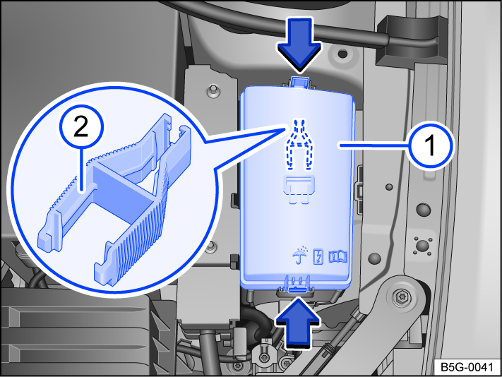
Fig. 173 In the engine compartment: Fuse box.
 Fuse box cover.
 Plastic pliers for pulling out fuses.
The plastic pliers for removing fuses can be found on the inside of the fuse box cover or on the fuse panel.
Removing the cover
-
Open the hood
 .
. -
Press the catches in the direction of the arrow
to release the fuse box cover. -
Remove the cover upward.
Fitting the cover
-
Place the cover onto the fuse box.
-
Push the cover downwards until it audibly clicks into place on both sides.
Fuse table for fuses in the engine compartment
Please read the introductory information and heed the Warnings and Notice and.
The list shows the fuse locations for the equipment relevant to the driver. The first column of the table contains the fuse slot; the other columns include the fuse version, current rating, and the protected equipment.
Depending on the market and the vehicle equipment, there may be differences from the fuse numbers and fuse slots listed in the table. If necessary, ask for the exact fuse assignment from suitably qualified professionals. Volkswagen recommends contacting an authorized Volkswagen dealer or authorized Volkswagen Service Facility.
Fuse assignment
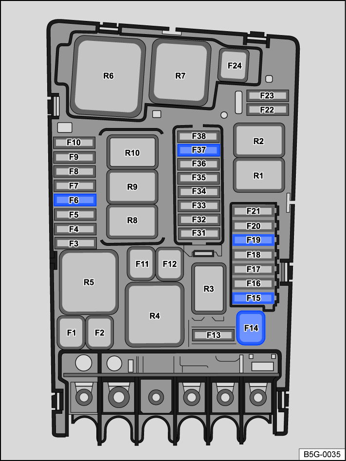
Fig. 174 Fuse locations in the engine compartment.
Fuse location :
- F6
- 7.5 Amp, ATO®, brake light sensor.
- F15
- 15 A, ATO®, horn.
- F19
- 30 Amp, ATO®, windshield wipers.
Fuses in the instrument panel
Please read the introductory information and heed the Warnings and Notice and.
Open and close the fuse box in the instrument panel
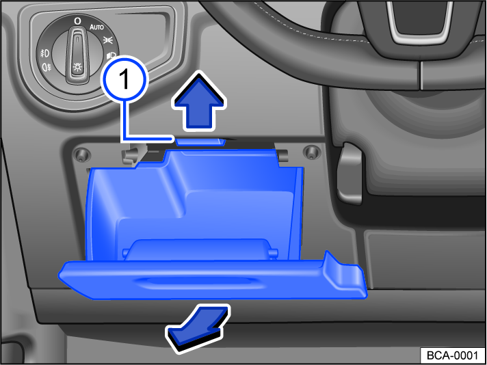
Fig. 175 On the driver side in the instrument panel: fuse box cover.
- Stop.
Removing the cover
-
Open the storage compartment on the driver's side and empty it, if necessary.
-
Push as far upwards as possible
and open the driver side stowage compartment again in the direction of the arrows and pull off.
Fitting the cover
-
Press the storage compartment into the mounts in the instrument panel until you hear the catch engage on both sides.
-
Close the storage compartment.
Fuse table for fuses in the instrument panel
Please read the introductory information and heed the Warnings and Notice and.
The list shows the fuse locations for the equipment relevant to the driver. The first column of the table contains the fuse slot; the other columns include the fuse version, current rating, and the protected equipment.
Depending on the market and the vehicle equipment, there may be differences from the fuse numbers and fuse slots listed in the table. If necessary, ask for the exact fuse assignment from suitably qualified professionals. Volkswagen recommends contacting an authorized Volkswagen dealer or authorized Volkswagen Service Facility.
Fuse assignment
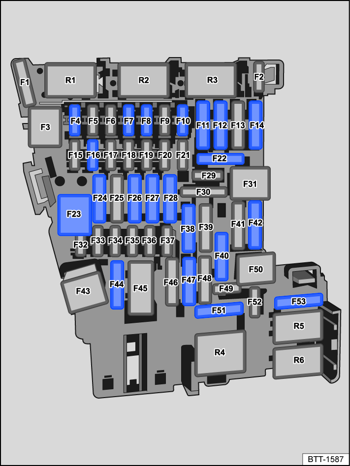
Fig. 176 Fuse assignment in the instrument panel.
Fuse locations :
- F4
- 7.5 Amp, MINI®, anti-theft alarm system.
- F6
- 10 A, ATO®, automatic transmission selector mechanism.
- F7
- 10 Amp, MINI®, control for the air conditioner or heating and fresh air system, rear window defroster relay.
- F8
- 7.5 Amp, MINI®, dipped beam light switch, rain/light sensor, electronic parking brake.
- F10
- 7.5 Amp, MINI®, Display, Infotainment system control panel.
- F11
- 40 Amp, ATO®, exterior lighting on the left side.
- F12
- 20 Amp, ATO®, Infotainment system.
- F14
- 40 Amp, ATO®, blower regulator.
- F16
- 7.5 Amp, MINI®, telephone.
- F23
- 20 Amp, JCASE®, power sunroof.
- F24
- 40 Amp, ATO®, exterior lighting on the right side.
- F26
- 30 Amp, ATO®, seat heating.
- F27
- 30 Amp, ATO®, interior lighting.
- F40
- 20 Amp, ATO®, cigarette lighter, sockets. Note the installation position, factory-standard fuse location as shown in the illustration.
- F42
- 40 Amp, ATO®, central locking system.
- F47
- 15 Amp, ATO®, rear window wiper.
- F51
- 25 Amp, ATO®, rear seat heating.
- F53
- 30 Amp, ATO®, rear window defroster.
Fuse locations for vehicles with a factory-installed trailer hitch.
- F22
- 15 amp, ATO®, trailer charging cable.
- F28
- 25 Amp, ATO®, left trailer control module.
- F38
- 25 Amp, ATO®, right trailer control module.
- F44
- 15 Amp, ATO®, trailer control module.
Power windows and seats can be protected by circuit breakers or control modules, which switch back on automatically several seconds after correcting the overload, for example when door windows are frozen shut.
Replacing blown fuses
Please read the introductory information and heed the Warnings and Notice and.
Preparations
-
Switch off the ignition, lights, and all other electrical equipment.
Detecting blown fuses
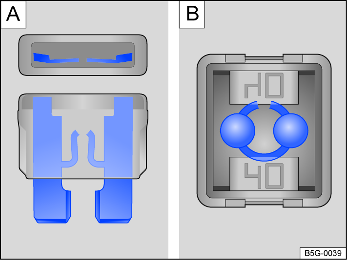
Fig. 177 Blown fuse (general example).
-
A blown flat connector fuse (ATO®, MINI®) has metal strips that have burned through, which you can see through the transparent housing from above and from the side
 .
. -
A blown block fuse (JCASE®) is recognizable by the melted metal strip seen through the transparent housing from above
 .
.
Fuse versions
-
Standard flat connector fuse (ATO®).
-
Small flat connector fuse (MINI®).
-
Block fuse (JCASE®).
Fuse color codes
Fuses (ATO® - MINI®).
- Color
- Current rating
- Black
- 1 A
- Purple
- 3 A
- Orange
- 5 A
- Brown
- 7.5 A
- Red
- 10 A
- Blue
- 15 A
- Yellow
- 20 A
- White or clear
- 25 A
- Green
- 30 A
- Light green
- 40 A
Fuses (JCASE®)
- Blue
- 20 A
- Pink
- 30 A
- Green
- 40 A
- Red
- 50 A
- Yellow
- 60 A
Replacing fuses
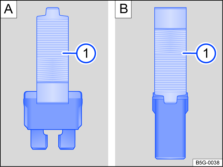
Fig. 178 Remove or install a fuse with the plastic pliers (general example).
- Plastic pliers.
-
Remove plastic tongs from either the fuse box or the cover of the fuse box
. -
Depending on the design of the fuse, slide the appropriately sized clamp on the plastic pliers onto the fuse from above or from the side .
-
Remove the fuse.
-
If a fuse is blown, replace with a fuse with the same rating (same color and same label) and the same size .
-
After inserting the new fuse, place the plastic pliers back in the cover, if necessary.
-
Reinstall the cover or close the fuse box cover.
NOTICE
If a fuse is replaced by a fuse with a higher current rating, this could damage the electrical system in another location.
Download Manual