Using the driving support systems
|
Driving assist system |
P.323
P.298
P.333
P.336
|
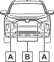
Sensors |
Two types of sensors, located behind the front grille and wind- shield, detect information neces- sary to operate the drive assist systems.
|
|
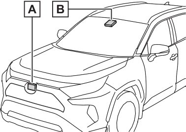
Radar sensor Front camera
Observe the following precau- tions.
Otherwise, the radar sensor may not operate properly, possibly leading to an accident resulting in death or serious injury.
If the front of the radar sensor or the front or back of the radar sen- sor cover is dirty or covered with water droplets, snow, etc., clean it.
Clean the radar sensor and radar sensor cover with a soft cloth to avoid damaging them.
If the radar sensor, front grille, or front bumper has been sub- jected to a strong impact, have the vehicle inspected by your Toyota dealer.
For vehicles sold in the U.S.A. and Hawaii
For vehicles sold in Canada
A system may be temporarily unavailable or there may be a malfunction in the system.
If the message does not disappear, contact your Toyota dealer.
|
Situation |
Actions |
|
When the area around a sensor is covered with dirt, moisture (fogged up, covered with condensation, ice, etc.), or other foreign matter |
To clean the part of the windshield in front of the front camera, use the windshield wipers or the windshield defogger of the air conditioning sys- tem (P.398). |
|
Situation |
Actions |
|
When the temperature around the front camera is outside of the opera- tional range, such as when the vehi- cle is in the sun or in an extremely cold environment |
If the front camera is hot, such as after the vehicle had been parked in the sun, use the air conditioning sys- tem to decrease the temperature around the front camera. If a sunshade was used when the vehicle was parked, depending on its type, the sunlight reflected from the surface of the sunshade may cause the temperature of the front camera to become excessively high. |
|
If the front camera is cold, such as after the vehicle is parked in an extremely cold environment, use the air conditioning system to increase the temperature around the front camera. |
|
|
The area in front of the front camera is obstructed, such as when the hood is open or a sticker is attached to the part of the windshield in front of the front camera. |
Close the hood, remove the sticker, etc. to clear the obstruction. |
If the message does not disappear, contact your Toyota dealer.
|
System functions |
The system can detect the fol- lowing:
When the system determines that the possibility of a frontal collision is high, the system applies greater braking force in relation to how strongly the brake pedal is depressed.
If the system determines that the possibility of a frontal colli- sion is extremely high, the brakes are automatically applied to help avoid the collision or reduce the impact of the colli- sion.
|
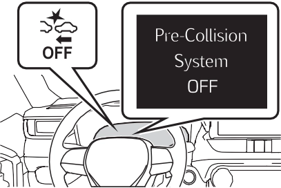
Changing settings of the pre-collision system |
enabled/disabled on the  screen (P.177) of the multi- information display.
The system is automatically enabled each time the power switch is turned to ON.
|
|
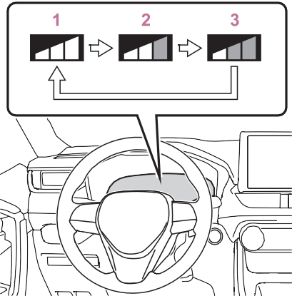
The pre-collision warning timing
can be changed on the  screen (P.177) of the multi- information display.
The warning timing setting is retained when the power switch is turned to OFF. However, if the pre- collision system is disabled and re- enabled, the operation timing will return to the default setting (mid- dle).
|
|
This is the default setting.
The pre-collision system is enabled and the system determines that the pos- sibility of a frontal collision with a detected object is high.
Each function is operational at the following speed
|
Detectable objects |
Vehicle speed |
Relative speed between your vehicle and object |
|
Vehicles |
Approx. 7 to 110 mph (10 to 180 km/h) |
Approx. 7 to 110 mph (10 to 180 km/h) |
|
Bicyclists and pedestri- ans |
Approx. 7 to 50 mph (10 to 80 km/h) |
Approx. 7 to 50 mph (10 to 80 km/h) |
|
Detectable objects |
Vehicle speed |
Relative speed between your vehicle and object |
|
Vehicles |
Approx. 20 to 110 mph (30 to 180 km/h) |
Approx. 20 to 110 mph (30 to 180 km/h) |
|
Bicyclists and pedestri- ans |
Approx. 20 to 50 mph (30 to 80 km/h) |
Approx. 20 to 50 mph (30 to 80 km/h) |
|
Detectable objects |
Vehicle speed |
Relative speed between your vehicle and object |
|
Vehicles |
Approx. 7 to 110 mph (10 to 180 km/h) |
Approx. 7 to 110 mph (10 to 180 km/h) |
|
Bicyclists and pedestri- ans |
Approx. 7 to 50 mph (10 to 80 km/h) |
Approx. 7 to 50 mph (10 to 80 km/h) |
The system may not operate in the following situations:
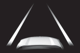
The system detects objects based on their size, profile, motion, etc. However, an object may not be detected depending on the sur- rounding brightness and the motion, posture, and angle of the detected object, preventing the system from operating properly. (P.320)
The illustration shows an image of detectable objects.
If either of the following occur while the pre-collision braking function is operating, it will be canceled:
the entrance of a curve
your vehicle
truck
such as heavy rain, fog, snow or a sandstorm

ing is displayed on the multi- information display, and either a warning buzzer will sound or the steering wheel will vibrate to alert the driver.
When the warning buzzer sounds or the steering wheel vibrates, check the area around your vehicle and carefully operate the steering wheel to move the vehicle back to the center of the lane.
When the system determines that the vehicle might depart from its lane and that the possibility of a col- lision with an overtaking vehicle in the adjacent lane is high, the lane departure alert will operate even if the turn signals are operating.
*: Boundary between asphalt and the side of the road, such as grass, soil, or a curb
from its lane or course*, the sys- tem provides assistance as nec- essary by operating the steering wheel in small amounts for a short period of time to keep the vehicle in its lane.
If the system detects that the steer- ing wheel has not been operated for a fixed amount of time or the steering wheel is not being firmly gripped, a warning is displayed on the multi-information display and the function is temporarily can- celed.
When the system determines that the vehicle might depart from its lane and that the possibility of a col- lision with an overtaking vehicle in the adjacent lane is high, the steer- ing assist function will operate even if the turn signals are operating.
*: Boundary between asphalt and the side of the road, such as grass, soil, or a curb
This function is linked with dynamic radar cruise control with full-speed range and pro- vides the required assistance by operating the steering wheel to keep the vehicle in its current lane.
When dynamic radar cruise control with full-speed range is not operat- ing, the lane centering function does not operate.
In situations where the white (yel- low) lane lines are difficult to see or are not visible, such as when in a
traffic jam, this function will operate to help follow a preceding vehicle by monitoring the position of the preceding vehicle.
If the system detects that the steer- ing wheel has not been operated for a fixed amount of time or the steering wheel is not being firmly gripped, a warning is displayed on the multi-information display and the function is temporarily can- celed.
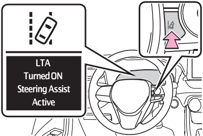
The LTA indicator illuminates and a message is displayed on the multi- information display.
When the LTA system is turned on or off, operation of the LTA system continues in the same condition the
next time the hybrid system is started.
|
|
|
Indications on multi-infor- mation display |
The illumination condition of the indicator informs the driver of the system operation status.
Illuminated in white: LTA system is operating.
Illuminated in green: Steering wheel assistance of the steering assist function or lane centering function is operating.
Flashing in orange: Lane departure alert function is operating.
Displayed when the multi-informa- tion display is switched to the driv- ing support system information display.
Indicates that steering wheel assis- tance of the steering assist function or lane centering function is operat- ing.
Both outer sides of the lane are dis- played: Indicates that steering wheel assist of the lane centering function is operating.
One outer side of the lane is dis- played: Indicates that steering wheel assist of the steering assist function is operating.
Both outer sides of the lane are flashing: Alerts the driver that their input is necessary to stay in the center of the lane (lane centering function).
Displayed when the multi-informa- tion display is switched to the driv- ing support system information display.
Indicates that steering assist of the lane centering function is operating by monitoring the position of a pre- ceding vehicle.
When the follow-up cruising display is displayed, if the preceding vehi- cle moves, your vehicle may move in the same way. Always pay care- ful attention to your surroundings and operate the steering wheel as necessary to correct the path of the vehicle and ensure safety.
Inside of displayed lines is white
|
|
Indicates that the system is recog- nizing white (yellow) lines or a course*. When the vehicle departs from its lane, the white line dis- played on the side the vehicle departs from flashes orange.
|
|
Indicates that the system is not able to recognize white (yellow) lines or a course* or is temporarily can- celed.
*: Boundary between asphalt and the side of the road, such as grass, soil, or a curb
Displayed when the multi-informa-
tion display is switched to the driv- ing support system information display.
lane lines or a course*2. (When a white [yellow] line or course*2 is recognized on only one side, the system will operate only for the recognized side.)
*1: The function operates even if the vehicle speed is less than approximately 32 mph (50 km/h) when the lane centering function is operating.
*2: Boundary between asphalt and the side of the road, such as grass, soil, or a curb
This function operates when all of the following conditions are met in addition to the operation conditions for the lane departure alert function.
screen of the multi-information display is set to “ON”. (P.170)
the following conditions are met.
screen of the multi-information display is set to “ON”. (P.170)
This function operates when all of the following conditions are met.
“Lane Center” in the screen of the multi-information display are set to “ON”. (P.170)
an adjacent lane.
*: Boundary between asphalt and the side of the road, such as grass, soil, or a curb
In the following situations, a warning message urging the driver to hold the steering wheel and the symbol shown in the illustration are dis- played on the multi-information dis- play to warn the driver. The warning stops when the system determines that the driver holds the steering wheel. Always keep your hands on the steering wheel when using this system, regardless of warnings.
If the driver continues to keep their hands off of the steering wheel, the buzzer sounds, the driver is warned and the function is temporarily can- celed. This warning also operates in the same way when the driver con- tinuously operates the steering wheel only a small amount.
The buzzer also sounds even if the alert type is set to “Steering wheel vibration”.
Depending on the vehicle condition and road conditions, the warning may not operate. Also, if the system determines that the vehicle is driv- ing around a curve, warnings will occur earlier than during straight- lane driving.
If the driver continues to keep their hands off of the steering wheel and the steering wheel assist is operat- ing, the buzzer sounds and the driver is warned. Each time the buzzer sounds, the continuing time of the buzzer becomes longer.
The buzzer also sounds even if the alert type is set to “Steering wheel vibration”.
When the system determines that the vehicle is swaying while the vehicle sway warning function is operating, a buzzer sounds and a warning message urging the driver to rest and the symbol shown in the illustration are simultaneously dis- played on the multi-information dis- play.
Depending on the vehicle and road conditions, the warning may not operate.
If the following warning message is displayed on the multi-information
display and the LTA indicator illumi- nates in orange, follow the appropri- ate troubleshooting procedure. Also, if a different warning message is displayed, follow the instructions displayed on the screen.
The system may not be operating properly. Have the vehicle inspected by your Toyota dealer.
The system is temporarily canceled due to a malfunction in a sensor other than the front camera. Turn the LTA system off, wait for a little while, and then turn the LTA system back on.
The function cannot be used as the vehicle speed exceeds the LTA operation range. Drive slower.
Function settings can be changed. (P.177)
 Do Not Enter sign (when notifica- tion is necessary)
be displayed in an overlapping stack under the current speed limit sign.
The following types of road signs, including electronic signs and blinking signs, are recog- nized.
A non-official or a recently intro- duced traffic sign may not be recog- nized.
 Speed limit
 Do Not Enter
 Stop
Stop
 Yield
Yield
nizes a do not enter sign and determines that your vehicle has entered a no-entry area, the displayed sign will flash and a buzzer will sound.
Depending on the situation, a notification function may not operate properly.
P.177
In the following situations, a dis- played speed limit sign and/or do not enter sign will stop being dis- played automatically:
In the following situations, stop and yield signs will stop being displayed automatically:
In the following situations, RSA does not operate normally and may not recognize signs, display the incorrect sign, etc. However, this does not indicate a malfunction.
the sun, etc. enters the front cam- era.
If the power switch was last turned off while a speed limit sign was dis- played on the multi-information dis- play, the same sign displays again
when the power switch is turned to ON.
The system may be malfunctioning. Have the vehicle inspected by your Toyota dealer.
Some functions can be customized. (Customizable features: P.177)
Indicators
Vehicle-to-vehicle distance switch
“+RES” switch
Cruise control main switch Cancel switch
“-SET” switch
|
|
|
Before using dynamic radar cruise control with full-speed range
Driving safely is the sole responsibility of the driver. Do not rely solely on the system, and drive safely by always pay- ing careful attention to your sur- roundings.
|
 WARNING
When driving on downhill slopes, the vehicle-to-vehicle distance may become shorter.
The vehicle travels at the speed set by the driver.
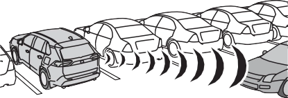
When a vehicle is detected running ahead of you, the system automatically decelerates your vehicle. When a greater reduction in vehicle speed is nec- essary, the system applies the brakes (the stop lights will come on at this time). The system will respond to changes in the speed of the vehicle ahead in order to maintain the vehicle-to-vehicle distance set by the driver. Approach warning warns you when the system cannot decelerate suffi- ciently to prevent your vehicle from closing in on the vehicle ahead.
When the vehicle ahead of you stops, your vehicle will also stop (vehicle is stopped by system control). After the vehicle ahead starts off, pressing the “+RES” switch or depressing the accelerator pedal (start-off operation) will resume follow-up cruising. If the start-off operation is not performed, system
control continues to keep your vehicle stopped.
When the turn signal lever is operated and your vehicle moves to an over- taking lane while driving at 50 mph (80 km/h) or more, the vehicle will accel- erate to help to overtake a passing vehicle.
The system’s identification of what is an overtaking lane may be deter- mined solely based on the location of the steering wheel in the vehicle (left side driver position versus right side driver position.) If the vehicle is driven to a region where the overtaking lane is on a different side from where the vehicle is normally driven, the vehicle may accelerate when the turn signal lever is operated in the opposite direction to the overtaking lane (e.g., if the driver normally operates the vehicle in a region where the overtaking lane is to the right but then drives to a region where the overtaking lane is to the left, the vehicle may accelerate when the right turn signal is activated).
When there are no longer any preceding vehicles driving slower than the set speed
The system accelerates until the set speed is reached. The system then returns to constant speed cruising.
(P.343)
Dynamic radar cruise control indi- cator will come on and a message will be displayed on the multi-infor- mation display. Press the switch again to deactivate the cruise con- trol.
If the cruise control main switch is pressed and held for 1.5 seconds or more, the system turns on in constant speed control mode.
Cruise control “SET” indicator will come on.
The vehicle speed at the moment the switch is released becomes the
set speed.
To change the set speed, press the “+RES” or “-SET” switch until the desired set speed is displayed.
Fine adjustment: Press the switch. Large adjustment: Press and hold the switch to change the speed,
and release when the desired
speed is reached.
speed will be increased or decreased as follows:
For the U.S. mainland and Hawaii
Fine adjustment: By 1 mph (1.6 km/h)*1 or 1 km/h (0.6 mph)*2 each time the switch is pressed
Large adjustment: Increases or decreases in 1 mph (1.6 km/h)*1 or 1 km/h (0.6 mph)*2 increments for as long as the switch is held
Fine adjustment: By 1 mph (1.6 km/h)*1 or 1 km/h (0.6 mph)*2 each time the switch is pressed
Large adjustment: Increases or decreases in 5 mph (8 km/h)*1 or 5 km/h (3.1 mph)*2 increments for as long as the switch is held
Fine adjustment: By 1 mph (1.6 km/h)*1 or 1 km/h (0.6 mph)*2 each time the switch is pressed
Large adjustment: The speed will continue to change while the switch is held.
*1: When the set speed is shown in “MPH”
*2: When the set speed is shown in “km/h”
Pressing the switch changes the vehicle-to-vehicle distance as follows:
The vehicle-to-vehicle distance is set automatically to long mode when the power switch is turned to ON.
If a vehicle is running ahead of you,
the preceding vehicle mark will also be displayed.
below. Note that the distances shown correspond to a vehicle speed of 50 mph (80 km/h).
Vehicle-to-vehicle distance increases/decreases in accor- dance with vehicle speed. When the vehicle is stopped by system control, the vehicle stops at a certain vehicle-to-vehicle dis- tance depending on the situa- tion.
|
Distance options |
Vehicle-to-vehi- cle distance |
|
Long |
Approximately 160 ft. (50 m) |
|
Medium |
Approximately 130 ft. (40 m) |
|
Short |
Approximately 100 ft. (30 m) |
|
Resuming follow-up cruising when the vehicle has been stopped by sys- tem control (vehicle-to- vehicle distance control mode) |
After the vehicle ahead of you starts off, press the “+RES” switch.
Your vehicle will also resume follow-up cruising if the acceler- ator pedal is depressed after the vehicle ahead of you starts off.
The speed control is also canceled when the brake pedal is depressed. (When the vehicle has been stopped by system control, depressing the brake pedal does not cancel the setting.)
When your vehicle is too close to a vehicle ahead, and suffi- cient automatic deceleration via
the cruise control is not possi- ble, the display will flash and the buzzer will sound to alert the driver. An example of this would be if another driver cuts in front of you while you are following a vehicle. Depress the brake pedal to ensure an appropriate vehicle-to-vehicle distance.
In the following instances, warn- ings may not occur even when the vehicle-to-vehicle distance is small.
|
Selecting constant speed control mode |
When constant speed control
mode is selected, your vehicle will maintain a set speed without controlling the vehicle-to-vehi- cle distance. Select this mode only when vehicle-to-vehicle dis- tance control mode does not function correctly due to a dirty radar, etc.
Immediately after the switch is pressed, the dynamic radar cruise control indicator will come on. After- wards, it switches to the cruise con- trol indicator.
Switching to constant speed control mode is only possible when operat- ing the switch with the cruise con- trol off.
Cruise control “SET” indicator will come on.
The vehicle speed at the moment the switch is released becomes the set speed.
Adjusting the speed setting:
P.341
Canceling and resuming the speed setting: P.343
The vehicle can accelerate by oper- ating the accelerator pedal. After accelerating, the set speed resumes. However, during vehicle- to-vehicle distance control mode, the vehicle speed may decrease below the set speed in order to maintain the distance to the preced- ing vehicle.
resumed.
Vehicle-to-vehicle distance control mode is automatically canceled in the following situations.
If vehicle-to-vehicle distance control mode is automatically canceled for any reasons other than the above, there may be a malfunction in the system. Contact your Toyota dealer.
Constant speed control mode is automatically canceled in the follow- ing situations:
turned off.
If constant speed control mode is automatically canceled for any rea- sons other than the above, there may be a malfunction in the system. Contact your Toyota dealer.
A brake operation sound may be heard and the brake pedal response may change, but these are not mal- functions.
Warning messages and buzzers are used to indicate a system malfunc- tion or to inform the driver of the need for caution while driving. If a warning message is shown on the multi-information display, read the message and follow the instructions. (P.313, 523)
In the case of the following and depending on the conditions, oper- ate the brake pedal when decelera- tion of the system is insufficient or operate the accelerator pedal when acceleration is required.
As the sensor may not be able to correctly detect these types of vehi- cles, the approach warning (P.343) may not be activated.
In the case of the following condi- tions, operate the brake pedal (or accelerator pedal, depending on the situation) as necessary.
As the sensor may not be able to correctly detect vehicles ahead, the system may not operate properly.
Turning the BSM function/RCTA function on/off.
BSM function:
When a vehicle is detected in a blind spot of the outside rear view mirrors or approaching rapidly from behind into a blind spot, the outside rear view mirror indicator on the detected side will illuminate. If the turn signal lever is operated toward the detected side, the outside rear view mirror indicator will flash.
RCTA function:
When a vehicle approaching from the right or left at the rear of the vehicle is detected, both outside rear view mirror indicators will flash.
If a vehicle approaching from the right or left at the rear of the vehicle is detected, the RCTA icon (P.353) for the detected side will be displayed.
When the Blind Spot Monitor is dis- abled, the BSM OFF indicator illu- minates.
When the RCTA function is dis- abled, the RCTA OFF indicator illu- minates.
If a vehicle approaching from the right or left at the rear of the vehicle is detected, a buzzer will sound from behind the rear seat.
RCTA function can be
enabled/disabled on the  screen of the multi-information display. (P.177)
The BSM function/RCTA function will be enabled each time the power switch is turned to ON.
In strong sunlight, the outside rear view mirror indicator may be difficult to see.
The RCTA buzzer may be difficult to hear over loud noises such as high audio volume.
The sensor voltage has become abnormal, or water, snow, mud, etc., may be built up in the vicinity of the sensor area of the rear bumper. (P.350)
Removing the water, snow, mud, etc., from the vicinity of the sensor area should return it to normal.
Also, the sensor may not function normally when used in extremely hot or cold weather.
There may be a sensor malfunction or misaligned. Have the vehicle inspected at a Toyota dealer.
Some functions can be customized. (P.177)
For vehicles sold in the U.S.A. and Hawaii
For vehicles sold in Canada
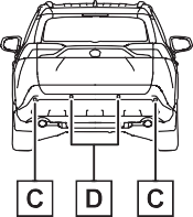
Blind Spot Monitor sensors are installed inside the left and right sides of the rear bumper respec- tively. Observe the following to ensure the Blind Spot Monitor can function correctly.
If a sensor or its surrounding area on the rear bumper is dirty or covered with snow, the Blind Spot Monitor may not operate and a warning message (P.348) will be displayed. In this situation, clear off the dirt or snow and drive the vehicle with the operation conditions of the BSM function (P.352) satis- fied for approximately 10 min- utes. If the warning message does not disappear, have the vehicle inspected by your Toyota dealer.
If a sensor is moved even slightly off position, the system may malfunction and vehicles may not be detected correctly. In the following situations, have your vehicle inspected by your Toyota dealer.
|
The Blind Spot Monitor function |
Vehicles that are approach- ing rapidly from behind in areas that are not visible using the outside rear view mirrors (the blind spots)
The areas that vehicles can be detected in are outlined below.
The range of each detection area is:
The area between the side of the vehicle and 1.6 ft. (0.5 m) from the side of the vehicle cannot be detected.
Approximately 9.8 ft. (3 m) from the rear bumper
Approximately 9.8 ft. (3 m) to 197 ft. (60 m) from the rear bumper
The greater the difference in speed between your vehicle and the detected vehicle is, the farther away the vehicle will be detected, causing the outside rear view mirror indicator to illuminate or flash.
The BSM function is operational when all of the following conditions are met:
The BSM function will detect a vehi- cle present in the detection area in the following situations:
The BSM function is not designed to detect the following types of vehi- cles and/or objects:
*: Depending on the conditions, detection of a vehicle and/or object may occur.
when driving on the edge of a lane, and the vehicle in an adja- cent lane is far away from your vehicle
|
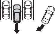
The Rear Cross Traffic Alert function |
|
|
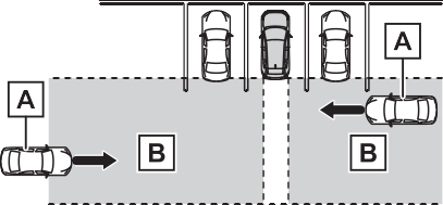
Approaching vehicles Detection areas
When a vehicle approaching from the right or left at the rear of the vehicle is detected, the following will be displayed on the navigation system (if equipped) or multimedia sys- tem (if equipped) screen.
Example:
The areas that vehicles can be detected in are outlined below.
The buzzer can alert the driver of faster vehicles approaching from farther away.
The RCTA function operates when all of the following conditions are met:
The buzzer volume can be adjusted on the multi-information display. (P.177)
The RCTA function is not designed to detect the following types of vehi- cles and/or objects.
*: Depending on conditions, detec- tion of a vehicle and/or object may occur.
driven on the street
*: If equipped
|
System components |
|
|
display)
When the sensors detect an object, such as a wall, a graphic
is shown on the multi-informa- tion display depending on the position and distance to the object.
Front corner sensor detection
Front center sensor detec- tion*1
Rear corner sensor detec- tion*2
Rear center sensor detec- tion*2
*1: Displayed when the shift lever is in a driving position
*2: Displayed when the shift lever is in R
A simplified image is displayed on
the upper corner of the screen when an obstacle is detected.
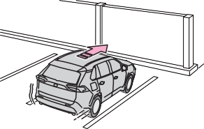
Panoramic view*
A graphic is shown when the pan- oramic view monitor is displayed.
*: A simplified image is displayed on the upper corner of the screen when an obstacle is detected while magnified display is shown.
A simplified image is displayed on the upper corner of the screen when an obstacle is detected.
|
Turning intuitive parking assist on/off |
be enabled/disabled on the  screen of the multi-information display. (P.177)
When the intuitive parking assist function is disabled, the intuitive parking assist OFF indicator (P.163) illuminates on the multi- information display.
 To re-enable the system, select on the multi-information display,
select  and turn it on.
If the system is disabled, it will remain off even if the power switch is turned to ON after the power switch has been turned off.
|
|
|
Intuitive parking assist pre- cautions
Observe the following precau- tions. Failing to do so may result in the vehicle being unable to be driven safely and possibly cause an acci- dent. Do not use the sensor at speeds in excess of 6 mph (10 km/h).
|
 WARNING

A sensor may be covered with ice, snow, dirt, etc. Remove the ice, snow, dirt, etc., from the sensor to return the system to normal.
Also, due to ice forming on a sensor at low temperatures, a warning message may be displayed or the sensor may not be able to detect an object. Once the ice melts, the sys- tem will return to normal.
If a warning message is displayed even if the sensor is clean, there may be a sensor malfunction. Have the vehicle inspected by your Toyota dealer.
Water may be continuously flowing over the sensor surface, such as in a heavy rain. When the system determines that it is normal, the sys- tem will return to normal.
detection distance may shorten, or detection may be impossible.
Certain vehicle conditions and the surrounding environment may affect the ability of a sensor to correctly detect objects. Particular instances where this may occur are listed below.
with parking assist sensors in the vicinity.
The shape of the object may pre- vent the sensor from detecting it. Pay particular attention to the fol- lowing objects:
People may not be detected if they are wearing certain types of cloth- ing.
This ISM device complies with Canadian ICES-001.
Approximately 4.9 ft. (150 cm)
Approximately 2.0 ft. (60 cm)
The diagram shows the detection range of the sensors. Note that the sensors cannot detect objects that are extremely close to the vehicle.
The range of the sensors may change depending on the shape of the object, etc.
The images may differ from that shown in the illustrations.
|
Multi-information display |
Navigation or multimedia system screen |
|
|
Multi-information display |
Navigation or multimedia system screen |
|
|
Multi-information display |
Navigation or multimedia system screen |
|
|
Multi-information display* |
Navigation or multimedia system screen |
|
*: The distance segments will blink slowly.
|
Multi-information display* |
Navigation or multimedia system screen |
|
*: The distance segments will blink rapidly.
When the vehicle comes
within approximately 1.0 ft. (30 cm) of the object, the buzzer sounds continuously.
operating, the buzzer will be muted in some situations. (automatic buzzer mute func- tion)
However, if another object is detected or the situation changes while the buzzer is muted, the buzzer begins sounding again.
muted by pressing  of the meter control switches while a suggestion that says mute is available is shown on the multi-information display.
Mute will be automatically canceled in the following situations.
The buzzer volume can be adjusted on the multi-information display. (P.177)
*: If equipped
|
PKSB (Parking Support Brake) system |
P.373
|
|
|
If “Parking Support Brake Unavailable” is displayed on the multi-information display and the PKSB OFF indicator illuminates
If this message is displayed immediately after the power switch is changed to ON, operate the vehicle carefully, paying atten- tion to your surroundings. It may be necessary to drive the vehicle for a certain amount of time before the system returns to nor- mal. (If the system does not return to normal after driving for a while, clean the sensors and their sur- rounding area on the bumpers.) |
 NOTICE
|
Enabling/Disabling the Parking Support Brake |
The Parking Support Brake can
be enabled/disabled on the  screen of the multi-information display. All of the Parking Sup- port Brake functions (static objects and rear-crossing vehi- cles) are enabled/disabled simultaneously. (P.177)
When the Parking Support Brake is disabled, the PKSB OFF indicator (P.163) illuminates on the multi- information display.
To re-enable the system, select  on the multi-information display,
select  and turn it on.
If the system is disabled, it will remain off even if the power switch is turned to ON after the power switch has been turned off.
Depending on the situation, hybrid system output restriction control will operate to either limit acceleration or restrict output as much as possi- ble.
Acceleration greater than a certain amount is restricted by the system.
Multi-information display and head- up display: “Object Detected Accel- eration Reduced” (no warning dis- played on the head-up display)
Navigation system or multimedia system screen: No warning dis- played
PKSB OFF indicator: Not illumi- nated
Buzzer: Does not sound
The system has determined that stronger-than-normal brake opera- tion is necessary.
Multi-information display and head- up display: “BRAKE!”
Navigation system or multimedia system screen: “BRAKE!”
PKSB OFF indicator: Not illumi- nated
Buzzer: Short beep
The system determined that emer- gency braking is necessary.
Multi-information display and head- up display: “BRAKE!”
Navigation system or multimedia system screen: “BRAKE!”
PKSB OFF indicator: Illuminated Buzzer: Short beep
The vehicle has been stopped by brake control operation.
Multi-information display and head- up display: “Switch to Brake” (If the accelerator pedal is not depressed, “Press Brake Pedal” will be dis- played.)
Navigation system or multimedia system screen: “Press Brake Pedal”
PKSB OFF indicator: Illuminated (If the accelerator pedal is not depressed, the indicator is not illu- minated.)
Buzzer: Short beep
|
System overview |
Hybrid system output Braking force
Time
Hybrid system output Braking force
Time
Hybrid system output restric- tion control begins operating (System determines that pos- sibility of collision with detected object is high)
Hybrid system output Braking force
Time
Hybrid system output restric- tion control begins operating (System determines that pos- sibility of collision with detected object is high)
Brake control begins operat- ing (System determines that possibility of collision with detected object is extremely high)
If the vehicle is stopped due to oper- ation of the Parking Support Brake, the Parking Support Brake will be disabled and the PKSB OFF indica- tor will illuminate. If the Parking Sup- port Brake operates unnecessarily, brake control can be canceled by depressing the brake pedal or wait- ing for approximately 2 seconds for it to automatically be canceled.
Then, the vehicle can be operated by depressing the accelerator pedal.
To re-enable the Parking Support Brake when it is disabled due to operation of the Parking Support Brake, either enable the system again (P.364), or turn the power switch off and then back to ON. Additionally, if the object becomes no longer in the traveling direction of the vehicle or if the traveling direc- tion of the vehicle changes (such as changing from moving forward to backing up, or from backing up to moving forward), the system will be re-enabled automatically.
from the sensor, or shown when the sensor was not dirty to begin with, have the vehicle inspected at your Toyota dealer.
*: If equipped
|
|
|
|
|
|
|
Types of sensors |
P.356
|
|
|
To ensure the Parking Sup- port Brake can operate prop- erly
Observe the following precautions regarding the sensors (P.356). Failure to do so may cause a sen- sor to not operate properly, and may cause an accident. Do not modify, disassemble or paint the sensors.
Do not replace a sensor with a part other than a genuine part.
Do not subject a sensor or its surrounding area to a strong impact.
Do not damage the sensors, and always keep them clean.
|
 WARNING

The function will operate when the PKSB OFF indicator is not illumi- nated (P.161, 163) and all of the following conditions are met:
The function will stop operating if any of the following conditions are met:
The detection range of the Parking
Support Brake function (static objects) differs from the detection range of the intuitive parking assist. (P.361) Therefore, even if the intuitive parking assist detects an object and provides a warning, the Parking Support Brake function (static objects) may not start operat- ing.
The sensors may not be able to detect certain objects, such as the following:
When the shift lever is in N
Regardless of whether the intuitive parking assist system is enabled or not (P.358), if the Parking Support Brake function (static objects) is enabled (P.364), the front or rear sensors detect an object and brake control and hybrid system output restriction control are performed, the intuitive parking assist buzzer will sound to notify the driver of the
approximate distance to the object.
In some situations, such as the fol- lowing, the Parking Support Brake function (static objects) may operate even though there is no possibility of a collision.
of water, such as when driving on a flooded road
In some situations, such as the fol- lowing, this function may not oper- ate properly.
*: If equipped
|
Examples of function operation |
|
|
P.350
|
|
|
To ensure the Parking Sup- port Brake (rear-crossing vehicles) can operate prop- erly
Observe the following precautions regarding the rear radar sensors (P.350). Failure to do so may cause a sensor to not operate properly, and may cause an acci- dent. Do not modify, disassemble or paint the sensors.
Do not replace a rear radar sen- sor with a part other than a gen- uine part.
Do not damage the rear radar sensors, and always keep the radar sensors and their sur- rounding area on the bumper clean.
If the area around a rear radar sensor is subjected to an impact, the system may not operate properly due to a sen- sor malfunction. Have the vehi- cle inspected by your Toyota dealer.
Observe the rear radar sensor handling precautions. (P.350)
|
 WARNING
The function will operate when the PKSB OFF indicator is not illumi- nated (P.161, 163) and all of the following conditions are met:
The function will stop operating if any of the following conditions are met:
The detection area of the Parking Support Brake function (rear-cross- ing vehicles) differs from the detec- tion area of the RCTA function (P.354). Therefore, even if the RCTA function detects a vehicle and provides an alert, the Parking Support Brake function (rear-cross- ing vehicles) may not start operat- ing.
The Parking Support Brake function (rear-crossing vehicles) is not designed to detect the following types of vehicles and/or objects:
cle*
*: Depending on the conditions, detection of a vehicle and/or object may occur.
In some situations such as the fol- lowing, the Parking Support Brake function (rear-crossing vehicles) may operate even though there is no possibility of a collision.
 When the distance between your vehicle and metal objects, such as a guardrail, wall, sign, or parked vehicle, which may reflect electri- cal waves toward the rear of the vehicle, is short
In some situations, such as the fol- lowing, the radar sensors may not detect an object and this function may not operate properly
 When turning while backing up
|
Selecting a driving mode |
|
|
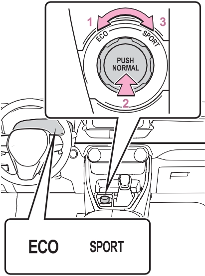
 Eco drive mode
Suitable for driving to improve fuel economy by more smoothly gener- ating torque in response to acceler- ator pedal operations compared to normal mode and restraining air conditioning system operations (heating/cooling).
When the switch is turned to the left while not in Eco drive mode, the system switches to Eco drive mode and the Eco drive mode indicator illuminates on the multi-information display.
Suitable for normal driving.
The driving mode returns to normal mode if the switch is pressed while in Eco drive mode or sport mode.
Controls the steering feeling and hybrid system to create an acceler- ation response that is suitable for sporty driving. Suitable for when crisp handling is desired, such as when driving on mountainous roads.
When the switch is turned to the right while not in sport mode, the system switches to sport mode and the sport mode indicator illuminates on the multi-information display.
returns to normal mode when the power switch is turned off.
In Eco drive mode, heating/cooling operations and the fan speed is con- trolled to improve fuel efficiency.
Perform the following procedures to increase the air conditioning perfor- mance.
When the switch is pressed, Trail Mode turns on and the Trail Mode indicator illuminates on the multi- information display.
When the switch is pressed again, the Trail Mode indicator turns off.
Trail Mode is intended for use when driving on bumpy rough roads. Do not turn the switch on in other situations.
Trail Mode controls the vehicle so that it can use the maximum amount of drive force when driving on bumpy roads.
If Trail Mode is continuously used for a long period of time, the load on related parts increases and the system may be unable to operate effectively.
In the following situations, Trail Mode is automatically canceled even if it is turned on.
When the driving mode is changed (P.377)
When the power switch is turned off
The following types of situations may occur, but they are not mal- functions.
Vibrations may be felt throughout the vehicle or steering wheel
Operating noise may be heard from the engine compartment
In the following situations, the sys- tem may be malfunctioning. Have the vehicle inspected by your Toyota dealer immediately.
|
Summary of the driving assist systems |
Helps to prevent wheel lock when the brakes are applied suddenly, or if the brakes are applied while driving on a slip- pery road surface
Generates an increased level of braking force after the brake pedal is depressed when the system detects a panic stop sit- uation
Helps the driver to control skid- ding when swerving suddenly or turning on slippery road sur- faces.
Provides cooperative control of the ABS, TRAC, VSC and EPS.
Helps to maintain directional stability when swerving on slip- pery road surfaces by con- trolling steering performance.
Helps the driver to control trailer sway by selectively applying brake pressure for individual wheels and reducing driving torque when trailer sway is detected.
Helps to maintain drive power and prevent the drive wheels from spinning when starting the vehicle or accelerating on slip- pery roads
Helps to prevent the vehicle from drifting to the outer side by
movement of the vehicle when starting on an uphill
Employs an electric motor to reduce the amount of effort needed to turn the steering wheel
Automatically switches from front wheel drive to all-wheel drive (AWD) according to the driving conditions, helping to ensure reliable handling and stability. Examples of condi- tions where the system will switch to AWD are when corner- ing, going uphill, starting off or accelerating, and when the road surface is slippery due to snow, rain, etc.
When the SRS airbag sensor detects a collision and the sys- tem operates, the brakes and brake lights are automatically controlled to reduce the vehicle speed and help reduce the pos- sibility of further damage due to a secondary collision.
performing inner wheel brake
control when attempting to accelerate while turning
Helps to reduce the backward
The slip indicator light will flash while the TRAC/VSC/ABS/Trailer Sway Control systems are operat- ing.
If the vehicle gets stuck in mud, dirt or snow, the TRAC system may reduce power from the hybrid sys- tem to the wheels.
Pressing  to turn the system off may make it easier for you to rock the vehicle in order to free it.
To turn the TRAC system off, quickly press and release .
“Traction Control Turned OFF” will be shown on the multi-information display.
Press  again to turn the system back on.
To turn the TRAC/VSC/Trailer Sway Control systems off, press and hold
 for more than 3 seconds while the vehicle is stopped.
The VSC OFF indicator light will come on and the “Traction Control Turned OFF” will be shown on the multi-information display.*
Press  again to turn the systems back on.
*: PCS will also be disabled (only Pre-Collision warning is avail- able). The PCS warning light will come on and a message will be displayed on the multi-information display. (P.322)
been disabled even if has not been pressed
TRAC is temporary deactivated. If the information continues to show, contact your Toyota dealer.
When the following four conditions are met, the hill-start assist control will operate:
The hill-start assist control will turn off in any of the following situations:
edly, when the hybrid system is started or just after the vehicle begins to move. This sound does not indicate that a malfunction has occurred in any of these systems.
ECB operating sound may be heard in the following cases, but it does not indicate that a malfunction has occurred.
When the Active Cornering Assist is operated, operation sounds and vibrations may be generated from the brake system, but this is not a malfunction.
When the steering wheel is oper- ated, a motor sound (whirring sound) may be heard. This does not indicate a malfunction.
After turning the TRAC, Trailer Sway Control and VSC systems off, the systems will be automatically re- enabled in the following situations:
If both the TRAC and VSC sys- tems are turned off, automatic re- enabling will not occur when vehi- cle speed increases.
The system operates when the fol- lowing occurs.
The effectiveness of the EPS sys- tem is reduced to prevent the sys- tem from overheating when there is frequent steering input over an extended period of time. The steer- ing wheel may feel heavy as a result. Should this occur, refrain from excessive steering input or stop the vehicle and turn the hybrid system off. The EPS system should return to normal within 10 minutes.
The system operates when the SRS airbag sensor detects a collision while the vehicle is in motion. How- ever, the system does not operate in any of the following situations.
The system is automatically can- celed in any of the following situa- tions.
during operation
Perform the following actions.
|
Message |
Details/Actions |
|
“AWD System Over- heated Switching to 2WD Mode” |
AWD system is overheating. Drive the vehicle at low speeds and stop the vehicle in a safe place with the hybrid sys- tem operating until the message is cleared. Once the display message on the multi-informa- tion display turns off, there is no problem continu- ing to drive. If the message does not disappear, have your vehicle checked by your Toyota dealer immedi- ately. |
|
“AWD System Over- heated 2WD Mode Engaged” |
The vehicle switched from all-wheel drive (AWD) to front wheel drive due to overheating. Drive the vehicle at low speeds and stop the vehicle in a safe place with the hybrid sys- tem operating until the message is cleared. Once the display message on the multi-informa- tion display turns off, the AWD system returns to normal. If the message does not disappear, have your vehicle checked by your Toyota dealer immedi- ately. |
|
“AWD System Malfunc- tion 2WD Mode Engaged Visit Your Dealer” |
A malfunction occurred in the AWD system. Have your vehicle checked by your Toyota dealer immediately. |
Download Manual