Do-it-yourself maintenance
The error code in the OBD sys- tem will not be cleared unless the vehicle is driven 40 or more times.
|
If your vehicle does not pass the I/M test |
Contact your Toyota dealer to prepare the vehicle for re-test- ing.
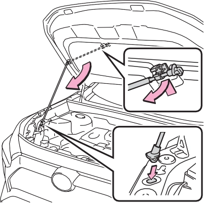
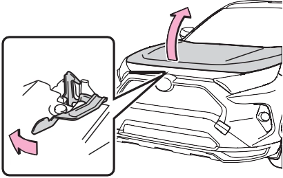
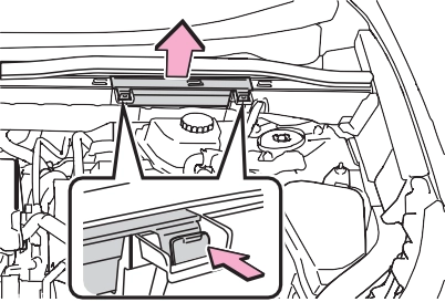
The hood will pop up slightly.
|
|
|
|
|
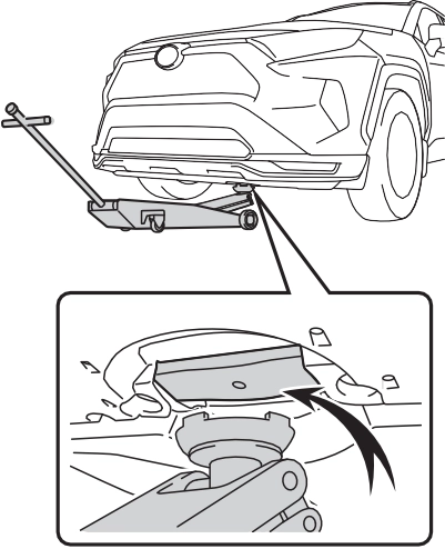
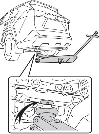
Location of the jack point |
|
|
|
|
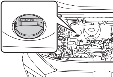
Engine compartment
Fuse boxes (P.495) Engine oil filler cap (P.461)
Engine oil level dipstick (P.460) Brake fluid reservoir (P.464) Radiator (P.463)
Electric cooling fan Condenser (P.463)
Power control unit coolant reservoir (P.463) Washer fluid tank (P.465)
Engine coolant reservoir (P.462)
P.466
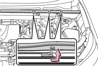
check the oil level on the dip- stick.
Low Normal Excessive
The shape of the dipstick may differ depending on the type of vehicle or engine.
Make sure to check the oil type and prepare the items needed before adding oil.
P.552
1.6 qt. (1.5 L, 1.3 Imp. qt.)
Clean funnel
|
|
A certain amount of engine oil will be consumed while driving. In the following situations, oil consump- tion may increase, and engine oil may need to be refilled in between oil maintenance intervals.
|
|
|
To prevent serious engine damage
Check the oil level on a regular basis. When replacing the engine oil
Be careful not to spill engine oil on the vehicle components.
Avoid overfilling, or the engine could be damaged.
Check the oil level on the dip- stick every time you refill the vehicle.
Be sure the engine oil filler cap is properly tightened.
If oil is spilled on the engine cover
To prevent the engine cover from being damaged, remove any engine oil from the engine cover as soon as possible using a neu- tral detergent. Do not use an organic solvent such as brake cleaner. |
 NOTICE
|
Checking the coolant |
|
|
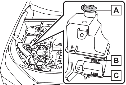
Reservoir cap “FULL” line “LOW” line
If the level is on or below the “LOW” line, add coolant up to the “FULL” line. (P.544)
|
|
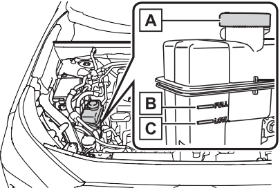
If the level is on or below the “LOW” line, add coolant up to the “FULL” line. (P.546)
Only use “Toyota Super Long Life Coolant” or a similar high quality ethylene glycol based non-silicate, non-amine, non-nitrite, and non- borate coolant with long-life hybrid organic acid technology.
U.S.A.:
“Toyota Super Long Life Coolant” is a mixture of 50% coolant and 50% deionized water. (Minimum tem- perature: -31°F [-35°C])
Canada:
“Toyota Super Long Life Coolant” is a mixture of 55% coolant and 45% deionized water. (Minimum tem- perature: -44°F [-42°C])
For more details about coolant, con- tact your Toyota dealer.
Visually check the radiators, hoses, engine/power control unit coolant reservoir caps, drain cock and water pump.
If you cannot find a leak, have your Toyota dealer, test the cap and check for leaks in the cooling sys- tem.
|
|
|
When the hybrid system is hot
Do not remove the engine/power control unit coolant reservoir caps. The cooling system may be under pressure and may spray hot cool- ant if the cap is removed, causing serious injuries, such as burns. |
 WARNING
If either of the above parts is extremely dirty or you are not sure of their condition, have
your vehicle inspected by your Toyota dealer.

The brake fluid level should be between the “MAX” and “MIN” lines on the tank.
|
|
|
|
Make sure to check the fluid type and prepare the necessary item.
|
Fluid type |
FMVSS No.116 DOT 3 or SAE J1703 brake fluid FMVSS No.116 DOT 4 or SAE J1704 brake fluid |
|
Item |
Clean funnel |
 Excess moisture in the brake fluid can cause a dangerous loss of brak- ing efficiency. Use only newly opened brake fluid.
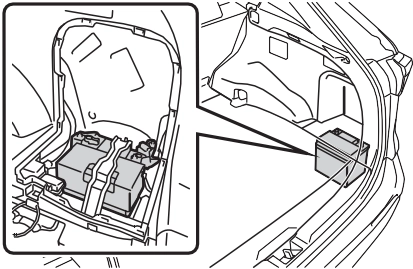
12-volt battery
The 12-volt battery is located in the right-hand side of luggage compartment.
|
|
When recharging, the 12-volt bat- tery produces hydrogen gas which is flammable and explosive. There- fore, observe the following precau- tions before recharging:
lock/unlock the doors.
If the hybrid system will not start even after multiple attempts at all methods above, contact your Toyota dealer.
|
|
|
Chemicals in the 12-volt bat- tery
The 12-volt battery contains poi- sonous and corrosive sulfuric acid and may produce hydrogen gas which is flammable and explosive. To reduce the risk of death or serious injury, take the following precautions while working on or near the 12-volt battery: Do not cause sparks by touch- ing the 12-volt battery terminals with tools.
Do not smoke or light a match near the 12-volt battery.
Avoid contact with eyes, skin and clothes.
Never inhale or swallow electro- lyte.
|
 WARNING
|
|
|
When recharging the 12-volt battery
Never recharge the 12-volt bat- tery while the hybrid system is operating. Also, be sure all acces- sories are turned off. |
 NOTICE
|
Removing the 12-volt bat- tery cover |
When installing the luggage side cover, make sure that the claws are installed securely.
|
|
|
Exterior |
clamps.
Terminals
Hold-down clamp
Check the battery condition by indicator color.
Blue: Good condition
Red: Charging is necessary.
Have the vehicle inspected by your Toyota dealer.
Add distilled water or replace the battery.
Have the vehicle inspected by your Toyota dealer.
|
Checking tires |
Check the spare tire condition and pressure if not rotated.
|
|
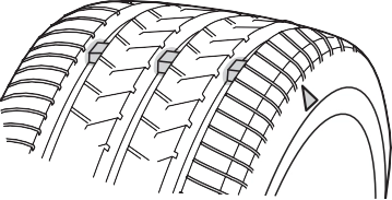
New tread Worn tread
Treadwear indicator
The location of treadwear indicators is shown by a “TWI” or “ ” mark,
etc., molded into the sidewall of each tire.
Replace the tires if the treadwear indicators are showing on a tire.
Summer tires are high-speed perfor- mance tires best suited to highway
driving under dry conditions. Since
Tires should be replaced if:
If you are not sure, consult with your Toyota dealer.
Any tire over 6 years old must be checked by a qualified technician even if it has seldom or never been used or damage is not obvious.
Check that the number given by dividing the maximum load by 1.10 of the replacement tire is greater than 1/2 of the Gross Axle Weight Ratings (GAWR) of either the front axle or the rear axle, whichever is greater.
For the GAWR, see the Certification Regulation Label. For the maximum load of the tire, see the load limit at maximum cold tire inflation pressure mentioned on the sidewall of the tire. (P.559)
summer tires do not have the same traction performance as snow tires, summer tires are inadequate for driving on snow-covered or icy roads. For driving on snow-covered roads or icy roads, the use of snow tires is recommended. When install- ing snow tires, be sure to replace all four tires.
All season tires are designed to pro- vide better traction in snow and to be adequate for driving in most win- ter conditions as well as for use year-round. All season tires, how- ever, do not have adequate traction performance compared with snow tires in heavy or loose snow. Also, all season tires fall short in accelera- tion and handling performance com- pared with summer tires in highway driving.
For driving on snow-covered roads or icy roads, we recommend using snow tires. If you need snow tires, select tires of the same size, con- struction and load capacity as the originally installed tires. Since your vehicle has radial tires as original equipment, make sure your snow tires also have radial construction. Do not install studded tires without first checking local regulations for possible restrictions. Snow tires should be installed on all wheels. (P.387)
The effectiveness of the tires as snow tires is lost.
|
|
|
When inspecting or replacing tires
Observe the following precautions to prevent accidents. Failure to do so may cause dam- age to parts of the drive train as well as dangerous handling char- acteristics, which may lead to an accident resulting in death or seri- ous injury. Do not mix tires of different makes, models or tread pat- terns.
Also, do not mix tires of remark- ably different treadwear. Do not use tire sizes other than those recommended by Toyota.
Do not mix differently con- structed tires (radial, bias-belted or bias-ply tires).
Do not mix summer, all season and snow tires.
Do not use tires that have been used on another vehicle.
Do not use tires if you do not know how they were used previ- ously. Do not tow if your vehicle has a compact spare tire installed.
|
 WARNING
|
|
|
Driving on rough roads
Take particular care when driving on roads with loose surfaces or potholes. These conditions may cause losses in tire inflation pressure, reducing the cushioning ability of the tires. In addition, driving on rough roads may cause damage to the tires themselves, as well as the vehicle’s wheels and body. If tire inflation pressure of each tire becomes low while driving
Do not continue driving, or your tires and/or wheels may be ruined. |
 NOTICE
|
Tire rotation |
To equalize tire wear and extend tire life, Toyota recommends that tire rotation is carried out at the same interval as tire inspection.
Do not fail to initialize the tire pres- sure warning system after tire rota- tion.
Make sure that the power switch is
OFF. If the tires are rotated while the power switch is in ON, the tire position information will not be updated. If this accidentally occurs, either turn the power switch to OFF and then to ON, or initialize the sys- tem after checking that the tire pres- sure is properly adjusted.
The tire pressure warning sys- tem of this vehicle adopts a 2- type warning system
The tire pressure warning light comes on and a buzzer sounds when the tire inflation pressure becomes low due to natural air leakage or outside temperature. (Ways of coping: P.518, 555)
The tire pressure warning light comes on and a buzzer sounds when the tire inflation pressure becomes low suddenly due to a blowout. (Ways of coping: P.518,
527) However, the system may not be able to detect sudden tire rup- tures (bursting, etc.).
tem can be displayed on the multi-information display.
The unit can be changed.
Changing the unit cannot be per- formed while the vehicle is moving.
ing wheel and select  .
.
press and hold  .
.
 “TPWS”, and then press .
 .
.
The tire pressure warning system does not replace routine tire inflation pressure checks. Make sure to check tire inflation pressure as part of your routine of daily vehicle checks.
The displayed values may also be different from the values mea- sured using a tire pressure gauge.
extremely higher than the speci- fied level.
If tire position information is not correctly displayed due to the radio wave conditions, the display may be corrected by driving and changing the radio wave condi- tions.
The warning of the tire pressure warning system will change in accordance with the conditions under which it was initialized. For this reason, the system may give a warning even if the tire pressure does not reach a low enough level, or if the pressure is higher than the pressure that was adjusted to when the system was initialized.
For vehicles sold in the U.S.A. and Hawaii
For vehicles sold in Canada
installed.
When new tire pressure warning valves and transmitters are installed, new ID codes must be registered in the tire pressure warning computer and the tire pressure warning system must
be initialized. (P.476)
If the ID code of the tire pressure warning valve and transmitter is not registered, the tire pressure warning system will not work properly. After driving for about 20 minutes, the tire pressure warning light blinks for 1 minute and stays on to indicate a system malfunction.
When the tire pressure warning system is initialized, the current tire inflation pressure is set as the benchmark pressure.
Initialization cannot be performed while the vehicle is moving.
Make sure to adjust the tire pres- sure to the specified cold tire infla- tion pressure level. The tire pressure warning system will oper- ate based on this pressure level.
 ing wheel and select .
press and hold  .
.
“TPWS” and then press  .
.
press and hold  .
.
“Set Pressure Accepted” will be dis- played on the multi-information dis- play and the tire pressure warning light will blink 3 times.
When the message disappears, ini- tialization is complete.
A message is displayed on the multi-information display. Also, “--” is displayed for inflation pressure of each tire on the multi-information display while the tire pressure warning system determines the position.
When initialization is complete, the inflation pressure of each tire will be displayed on the multi-information display.
Even if the vehicle is not driven at approximately 25 mph (40 km/h) or more, initialization can be com- pleted by driving for a long time.
However, if initialization does not complete after driving for 1 hour or more, park the vehicle in a safe place for approximately 20 minutes and then drive the vehicle again.
If initialization cannot be completed after performing the above proce- dure, contact your Toyota dealer.
|
|
|
When initializing the tire pres- sure warning system
Do not initialize tire inflation pres- sure without first adjusting the tire inflation pressure to the specified level. Otherwise, the tire pressure warning light may not come on even if the tire inflation pressure is low, or it may come on when the tire inflation pressure is actually normal. |
 WARNING
|
Registering ID codes |
When registering the ID codes, perform the following procedure.
 ing wheel and select .
or of the meter
control switches and select
“Vehicle Settin and then
Even if the vehicle is not driven at
“TPWS”, and then press  .
.
and hold  until the tire pressure warning light starts slowly blinking 3 times.
The change wheel set mode is acti- vated and registration is started.
Then a message will be displayed on the multi-information display.
When registration is being per- formed, the tire pressure warning light will blink for approximately 1 minute then illuminate and “--” will be displayed for the inflation pres- sure of each tire on the multi-infor- mation display.
When registration is completed, the tire pressure warning light will go off and the inflation pressure of each tire will be displayed on the multi- information display.
approximately 25 mph (40 km/h) or more, registration can be com- pleted by driving for a long time.
However, if registration does not complete after driving for 1 hour or more, perform the procedure again from the beginning.
 again.
ing system will be operational when the tire pressure warning light turns off.
If ID code registration is not com- plete after driving for approxi- mately 30 minutes, continue driving for a while.
If registration does not complete after driving for 1 hour or more, per- form the ID code registration proce- dure again from the beginning.
erly. Perform the ID code registra- tion procedure again.
|
Selecting wheel set |
After registration of a second wheel set, either of these two wheel sets can be selected for usage with the tire pressure warning system.
registered wheel set is possi- ble, mixing between these wheel sets is not supported.
ing wheel and select  .
.
press and hold .
“TPWS”, and then press  .
.
and hold  until the tire pressure warning light starts slowly blinking 3 times.
Afterward, the tire pressure warning light turns on after flashing for 1 minute.
After 2 minutes, registration of a second wheel set is being per- formed. The tire pressure warn- ing light will turn off and “--” will be displayed for the inflation pressure of each tire on the multi-information display.
If the tire inflation pressure settings for the installed tires change, initial- ization operations are required, but if the tire inflation pressure settings are the same, initialization is not required.
Registration of a second wheel set is complete when the tire pressure warning light turns off and the infla- tion pressure of each tire is dis- played on the multi-information display.
Tire valve
Tire pressure gauge
You should check tire inflation pres- sure every two weeks, or at least once a month.
 Do not forget to check the spare.
Driving with incorrect tire inflation pressure may result in the following:
If a tire needs frequent inflating, have it checked by your Toyota dealer.
When checking tire inflation pres- sure, observe the following:
If your vehicle has been parked for at least 3 hours or has not been driven for more than 1 mile or 1.5 km, you will get an accurate cold tire inflation pressure reading.
|
Wheel selection |
Replacement wheels are avail- able at your Toyota dealer.
*: Conventionally referred to as off- set.
The wheels of your vehicle are equipped with tire pressure warning valves and transmitters that allow the tire pressure warning system to provide advance warning in the event of a loss in tire inflation pres- sure. Whenever wheels are replaced, tire pressure warning valves and transmitters must be installed. (P.471, 483)
|
|
|
Replacing tire pressure warn- ing valves and transmitters
Because tire repair or replace- ment may affect the tire pres- sure warning valves and transmitters, make sure to have tires serviced by your Toyota dealer or other qualified service shop. In addition, make sure to purchase your tire pressure warning valves and transmit- ters at your Toyota dealer.
Ensure that only genuine Toyota wheels are used on your vehicle.
Tire pressure warning valves and transmitters may not work properly with non-genuine wheels. |
 NOTICE
Air conditioning filter
|
Removal method |
Confirm that the charging connec- tor is not connected. Also, do not use the Remote Air Conditioning System during the procedure.
By keeping the door open, unex- pected operation of the Remote Air Conditioning System can be pre- vent. (P.405)
|
|
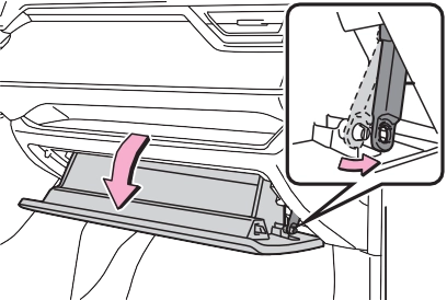
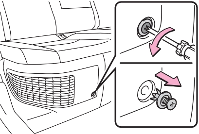
fully open the glove box while supporting it.
Do not use excessive force if the glove box does not detach when lightly pulled. Instead, pull toward the seat while slightly adjusting the height of the glove box.
|
|
|
|
The “ UP” marks shown on the filter should be pointing up.
pull the filter cover out of the
Inspect and replace the air condi-
tioning filter according to the mainte- nance schedule. In dusty areas or areas with heavy traffic flow, early replacement may be required. (For scheduled maintenance information, please refer to the “Owner’s Manual Supplement” or “Scheduled Mainte- nance”.)
The filter may be clogged. Check the filter and replace if necessary.
|
|
|
When replacing the air condi- tioning filter
Observe the following precau- tions. Failure to do so may result in the air conditioning system operating during the procedure, possibly resulting in injury. Check that the charging con- nector is not connected
The air conditioning may operate due to the “Climate Prep” (P.131) setting. Do not use the Remote Air Con- ditioning System
|
 WARNING
|
|
|
When using the air condition- ing system
Make sure that a filter is always installed. Using the air condition- ing system without a filter may cause damage to the system. When removing the glove box
Always follow the specified proce- dure to remove the glove box (P.483). If the glove box is removed without following the specified procedure, the hinge of the glove box may become dam- aged. |
 NOTICE
|
If dust and clogs cannot be completely removed |
|
|
Remove the dust from the air intake vent with a vacuum cleaner, etc.
Make sure to only use a vacuum to suck out dust and clogs. Attempting to blow out dust and clogs using an airgun, etc. may push it into the air intake vent. (P.488)
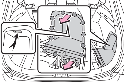
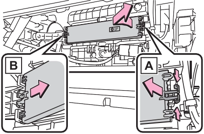
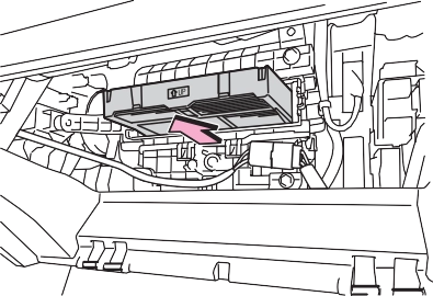
Pull the cover as shown in the illus- tration to disengage the 8 claws, starting from the claw in the upper right corner and pull the cover toward the front of the vehicle to remove it.
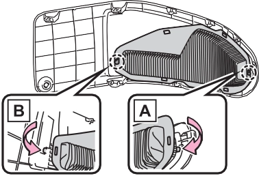
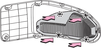
Disengage the 4 center claws from
the filter.
Disengage the claws in the order of and to remove the filter from
the cover.
Make sure to also remove the dust and clogs from the inside of the air intake vent cover.
Engage the claws in the order of
and .
|
|
Engage the 4 center claws to install the filter.
Make sure that the filter is not crooked or deformed when install- ing it.
|
|
Insert the tab of the cover as shown in the illustration and push the cover to engage the 8 claws.
 Install the clip.
|
|
It may take approximately 20 min- utes after the hybrid system is started until the warning message disappears. If the warning mes- sage does not disappear, have the vehicle inspected by your Toyota dealer.
|
Windshield wipers |
When returning the wiper arms to their original positions, first lower the passenger side, and then lower the driver side.
|
|
To prevent damage to the wiper arm, protect the tip of the screw-
driver with a rag.
When installing, reverse the steps listed.
Stopper Claw
from the wiper insert pulled out, and install the plates to a new wiper insert.
Make sure that the cutout location and warp direction of the metal blades are same as the original.
|
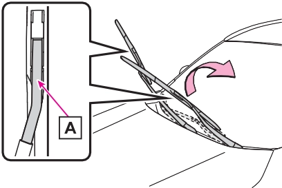
Rear window wiper |
the claw detaches, and then remove the wiper blade from the wiper arm.
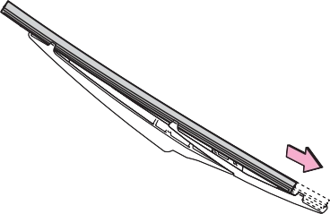
Lightly grasp between the claws of the wiper blade to allow the wiper insert to lift up, making it easier to remove.
install them to the replace- ment wiper insert.
Applying a small amount of washer fluid to the wiper insert can make it easier to insert the claws into the grooves.
|
|
If the wiper blade claws are not fit- ted in the grooves of the wiper insert, grasp the wiper insert and slide it back and forth multiple times to insert the claws into the grooves.
Lightly lift up the center of the wiper insert to make the rubber easier to
slide.
|
|
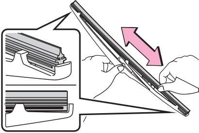
After installing the wiper blade, check that the connection is locked.
Improper handling may result in damage to the wiper blades or wiper insert. If you have any concerns about replacing the wiper blades or wiper insert yourself, contact your Toyota dealer.
|
|
|
When lifting the windshield wipers
When raising the wiper arms off the windshield, lift up the driver side first, and then lift up pas- senger side. When returning the wipers to their original position, return the passenger side first.
Do not lift a windshield wiper by the wiper blade. Otherwise, the wiper blade may be deformed.
Do not operate the wiper lever when the windshield wipers are lifted. Otherwise, the wind- shield wipers may contact the hood, possibly resulting in dam- age to the windshield wipers and/or hood.
|
 NOTICE
The following symptoms may occur:
Prepare the following before replacing the battery:
|
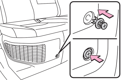
Replacing the battery |
|
|
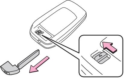
Use a screwdriver of an appropriate size. Forcedly prying may cause the cover damaged.
To prevent damage to the key, cover the tip of the flathead screw- driver with a rag.
|
|
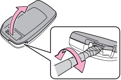
When removing the cover, the elec- tronic key module may stick to the cover and the battery may not be visible. In this case, remove the electronic key module in order to remove the battery.
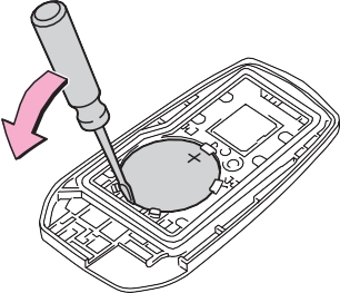
Insert a new battery with the “+” ter-
minal facing up.
|
|
Remove the lid.
Confirm that the charging connec- tor is not connected. Also, do not use the Remote Air Conditioning System during the procedure.
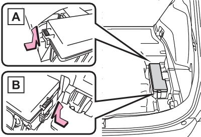
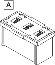
Engine compartment: Type A fuse box
Push claw and to com- pletely release the lock, and then lift up the cover.
Push claw and to com- pletely release the lock, and then lift up the cover.
Open the deck board. (P.417)
Push claw and to com- pletely release the lock, and then lift up the cover.
|
|
Only type A fuse can be removed
using the pullout tool.
Replace the blown fuse with a new fuse of an appropriate amperage rating. The amperage rating can be found on the fuse box lid.
Type A
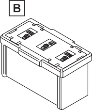
Type B
Type C
|
|
The fuses are designed to blow, protecting the wiring harness from damage.
Toyota recommends that you use genuine Toyota products designed for this vehicle. Because certain bulbs are connected to circuits designed to prevent overload, non- genuine parts or parts not designed for this vehicle may be unusable.
|
Preparing for light bulb replacement |
|
Bulb location |
|
|
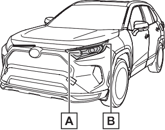
Front turn signal lights Front side marker lights
Rear
replaced by your Toyota dealer
The lights other than the following lights each consist of a number of LEDs. If any of the LEDs burn out, take your vehicle to your Toyota dealer to have the light replaced.
Temporary condensation build-up on the inside of the light lens does not indicate a malfunction. Contact your Toyota dealer for more infor- mation in the following situations:
P.496
|
Replacing light bulb |
|
|
|
|
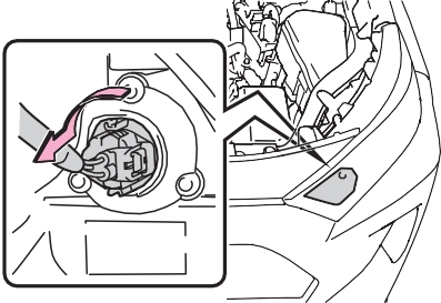
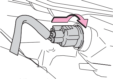
light unit by inserting it and turning the bulb base clock- wise.
turning the bulb base clock- wise.
|
|
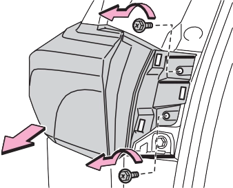
Remove the lamp assembly by pull- ing it directly backward from the rear of the vehicle.
|
|
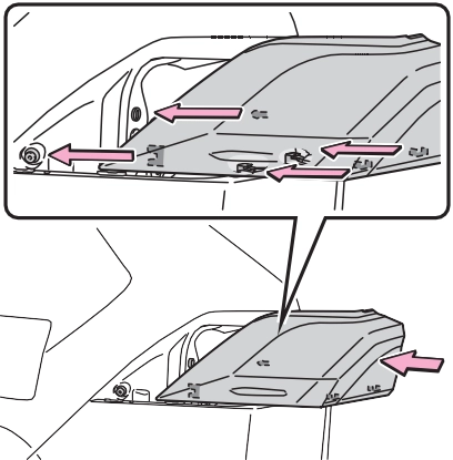
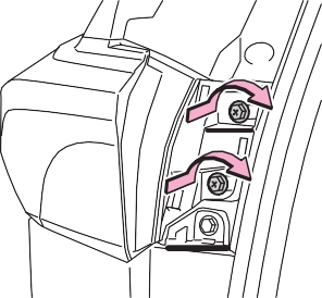
Confirm that the light unit is com- pletely secured.
|
|
|
|
1 Open the back door and remove the cover.
To prevent damage to the cover, protect the tip of the screwdriver
with a rag.
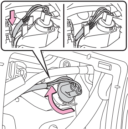
Remove the cord from the clip before turning the bulb base.
Secure the cord with the clip back again after installing the bulb base.
|
|
|
|
|
Replacing light bulb
Turn off the light. Do not attempt to replace the bulb immediately after turning off the light.
The bulb become very hot and may cause burns. Do not touch the glass portion of the light bulb with bare hands. When it is unavoidable to hold the glass portion, use and hold with a clean dry cloth to avoid getting moisture and oils on the bulb.
Also, if the bulb is scratched or dropped, it may blow out or crack. Fully install light bulb and any parts used to secure it. Failure to do so may result in heat dam- age, fire, or water entering the light unit. This may damage the light or cause condensation to build up on the lens.
Do not attempt to repair or dis- assemble light bulbs, connec- tors, electric circuits or component parts.
Doing so may result in death or serious injury due to electric shock. To prevent damage or fire
Make sure bulb is fully seated and locked.
Check the wattage of the bulb before installing to prevent heat damage.
|
 WARNING
When trouble arises 8
.................................. 544
If the vehicle becomes stuck
.................................. 548
503
8
Download Manual