TRAILER TOWING
In this section you will find safety tips and information on limits to the type of towing you can reasonably do with your vehicle. Before towing a trailer, carefully review this information to tow your load as efficiently and safely as possible.
To maintain the New Vehicle Limited Warranty coverage, follow the requirements and recommendations in this manual concerning vehicles used for trailer towing.
COMMON TOWING DEFINITIONS
The following trailer towing-related definitions will assist you in understanding the following information:
The GVWR is the total allowable weight of your vehicle. This includes driver, passengers, cargo and tongue weight. The total load must be limited so that you do not exceed the GVWR
page 235.
The GTW is the weight of the trailer plus the weight of all cargo, consumables and
equipment (permanent or temporary) loaded in or on the trailer in its "loaded and ready for operation" condition.
The recommended way to measure GTW is to put your fully loaded trailer on a vehicle scale. The entire weight of the trailer must be supported by the scale.
If the gross trailer weight is 5,000 lbs
(2,267 kg) or more, it is recommended to use a weight-distributing hitch to ensure stable handling of your vehicle. If you use a standard weight-carrying hitch, you could lose control of your vehicle and cause a collision.
The TW is the downward force exerted on the hitch ball by the trailer. You must consider this as part of the load on your vehicle.
The frontal area is the maximum height
individual wheel brakes and/or reduces engine power to attempt to eliminate the trailer sway.
A weight-carrying hitch supports the trailer tongue weight, just as if it were luggage located at a hitch ball or some other connecting point of the vehicle. These kinds of hitches are commonly used to tow small and medium sized
trailers. 4
A weight-distributing system works by applying leverage through spring (load) bars. They are typically used for heavier loads to distribute trailer tongue weight to the tow vehicle's front
multiplied by the maximum width of the front of
axle and the trailer axle(s). When used in
The GCWR is the total allowable weight of your vehicle and trailer when weighed in combination.
The GAWR is the maximum capacity of the front and rear axles. Distribute the load over the front and rear axles evenly. Make sure that you do not exceed either front or rear GAWR
page 235.
a trailer.
The TSC can be a mechanical telescoping link that can be installed between the hitch receiver and the trailer tongue that typically provides adjustable friction associated with the telescoping motion to dampen any unwanted trailer swaying motions while traveling.
If equipped, the electronic TSC recognizes a swaying trailer and automatically applies
accordance with the manufacturer's directions, it provides for a more level ride, offering more consistent steering and brake control, thereby enhancing towing safety. The addition of a friction/hydraulic sway control also dampens sway caused by traffic and crosswinds and contributes positively to tow vehicle and trailer stability. Trailer Sway Control (TSC) and a weight distributing (load equalizing) hitch are recommended for heavier Tongue Weights (TW)
and may be required depending on vehicle and trailer configuration/loading to comply with GAWR requirements.
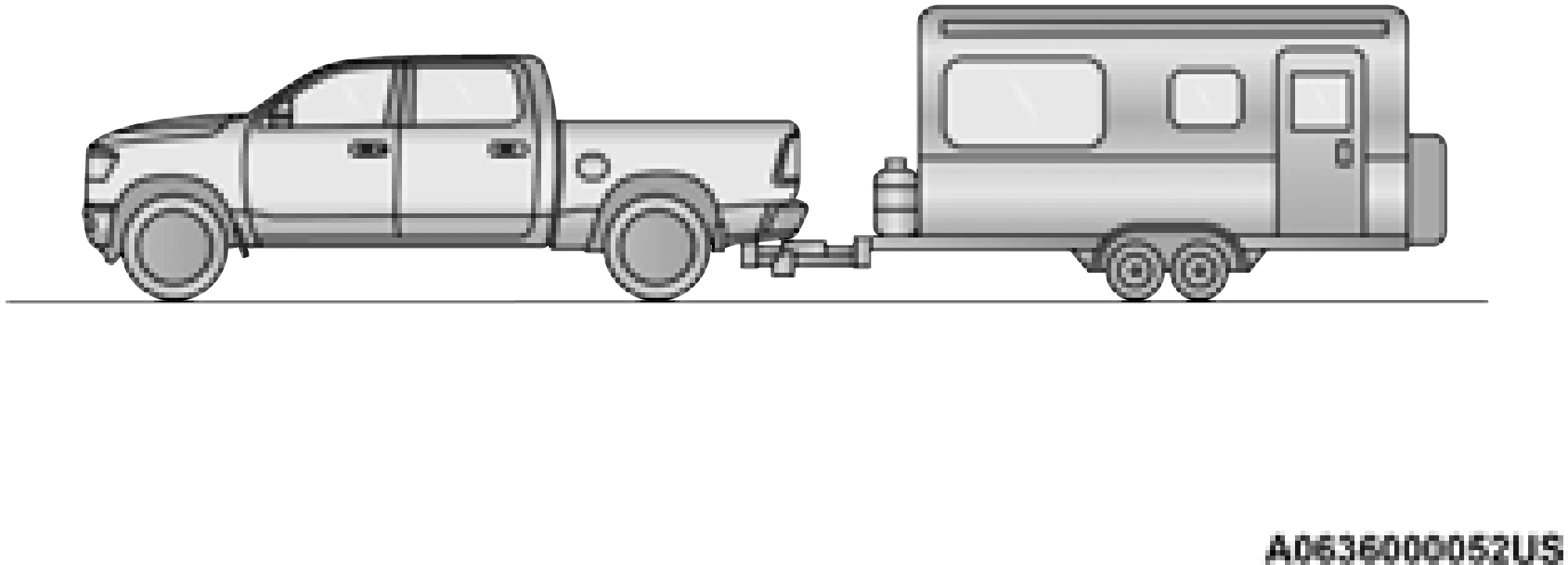
Without Weight-Distributing Hitch (Incorrect)
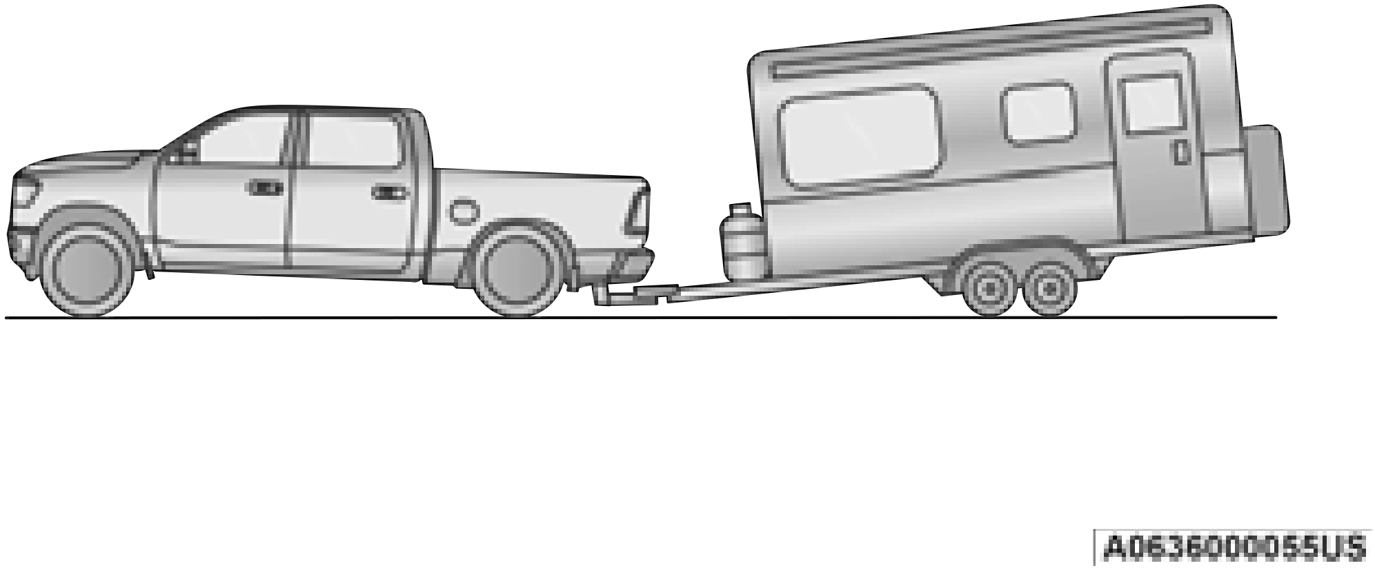
Improper Adjustment Of Weight-Distributing Hitch (Incorrect)
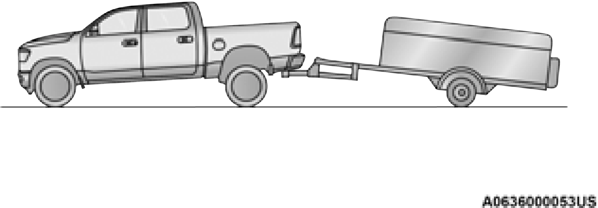
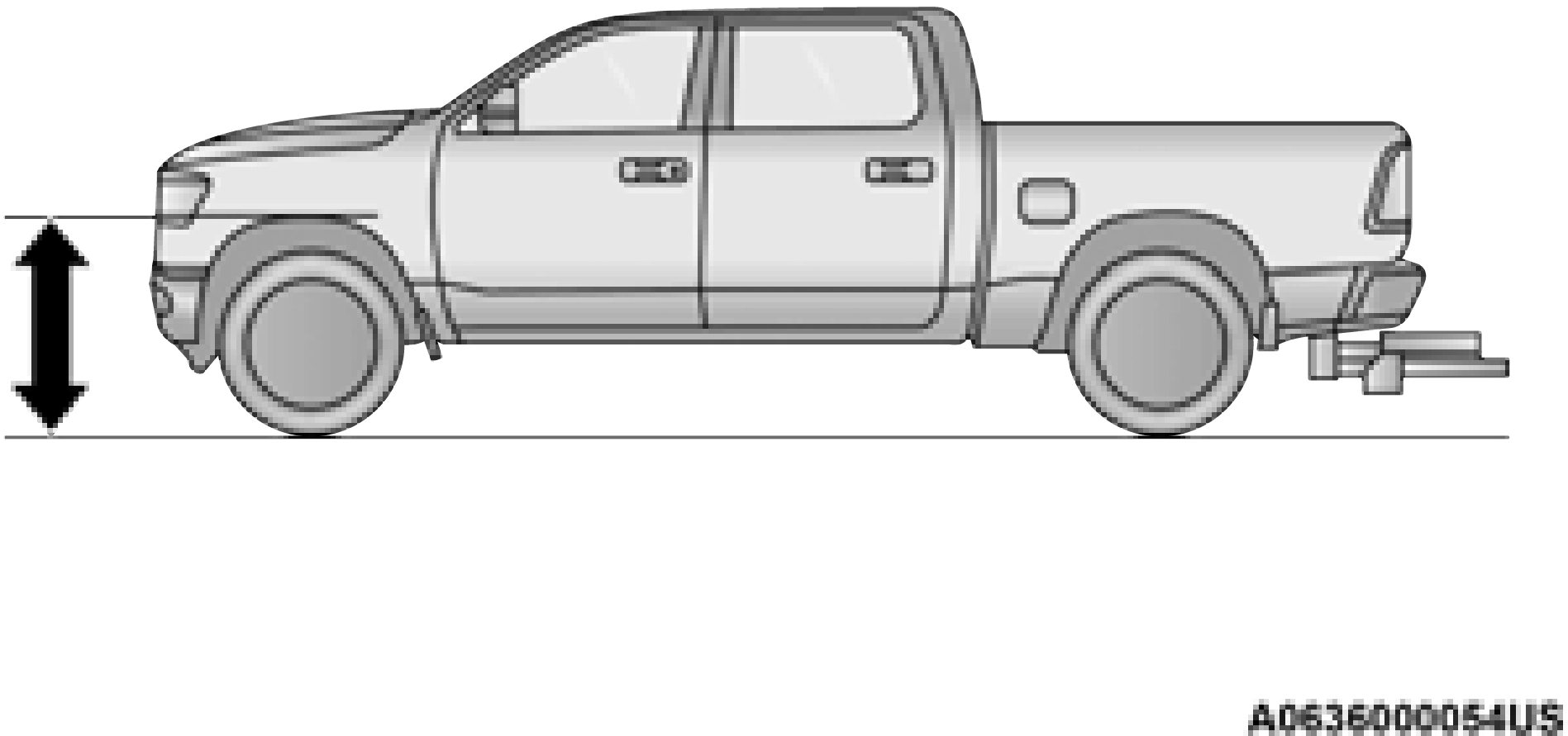
Recommended Distribution Hitch Adjustment Towing With 2500/3500 Air Suspension
Normal Ride Height (NRH) or Alternate Trailer Height (ATH) can be used. The vehicle must remain in the engine running position while attaching a trailer for proper leveling of the air suspension system. It may not be possible to enter Alternate Trailer Height (ATH) while lightly loaded.
|
Measurement Example |
Example 2500/3500 Height (mm) |
|
H1 |
1030 |
|
H2 |
1058 |
|
H2-H1 |
28 |
|
(H2-H1)/2 |
14 |
|
(H2-H1)/2 + H1 |
1044 |
For all towing conditions, we recommend towing with TOW/HAUL mode engaged.
manufacturer’s recommendations have been met.
4
For all towing conditions, we recommend towing with TOW/HAUL mode engaged.
The fifth-wheel hitch is a special high platform with a coupling that mounts over the rear axle of the tow vehicle in the truck bed. It connects a vehicle and fifth-wheel trailer with a coupling king pin.
Your truck may be equipped with a fifth wheel hitch option. Refer to the separately provided fifth wheel hitch safety, care, assembly, and operating instructions.
The gooseneck hitch employs a pivoted coupling arm which attaches to a ball mounted in the bed of a pickup truck. The coupling arm connects to the hitch mounted over the rear axle in the truck bed.
TRAILER HITCH TYPE AND MAXIMUM TRAILER WEIGHT
The following chart provides the maximum trailer weight a given factory equipped trailer hitch type can tow and should be used to assist
you in selecting the correct trailer hitch for your intended towing condition.
|
Trailer Hitch Type and Maximum Trailer Weight |
|
|
Hitch Type |
Max. Trailer Weight / Max. Tongue Weight |
|
Class V - 2500 Models |
20,000 lb (9,071 kg) / 2,000 lb (907 kg) |
|
Class V - 3500 Models |
23,000 lb (10,432 kg) / 2,300 lb (1,043 kg) |
|
Fifth Wheel - 2500 Models |
25,000 lb (11,339 kg) / 3,750 lb (1,700 kg) |
|
Fifth Wheel - 3500 Models |
30,000 lb (13,607 kg) / 4,500 lb (2,041 kg) |
|
Gooseneck - 2500 Models |
20,000 lb (9,071 kg) / 3,000 lb (1,360 kg) |
|
Gooseneck - 3500 Models |
35,250 lb (15,989 kg) / 5,287 lb (2,398 kg) |
|
Refer to the “Trailer Towing Weights (Maximum Trailer Weight Ratings)” for the Maximum Gross Trailer Weight (GTW) towable for your given drivetrain. |
All trailer hitches should be professionally installed on your vehicle.
TRAILER TOWING WEIGHTS (MAXIMUM TRAILER WEIGHT RATINGS)
For trailer towing information (maximum trailer weight ratings) refer to the following website addresses:
TRAILER AND TONGUE WEIGHT
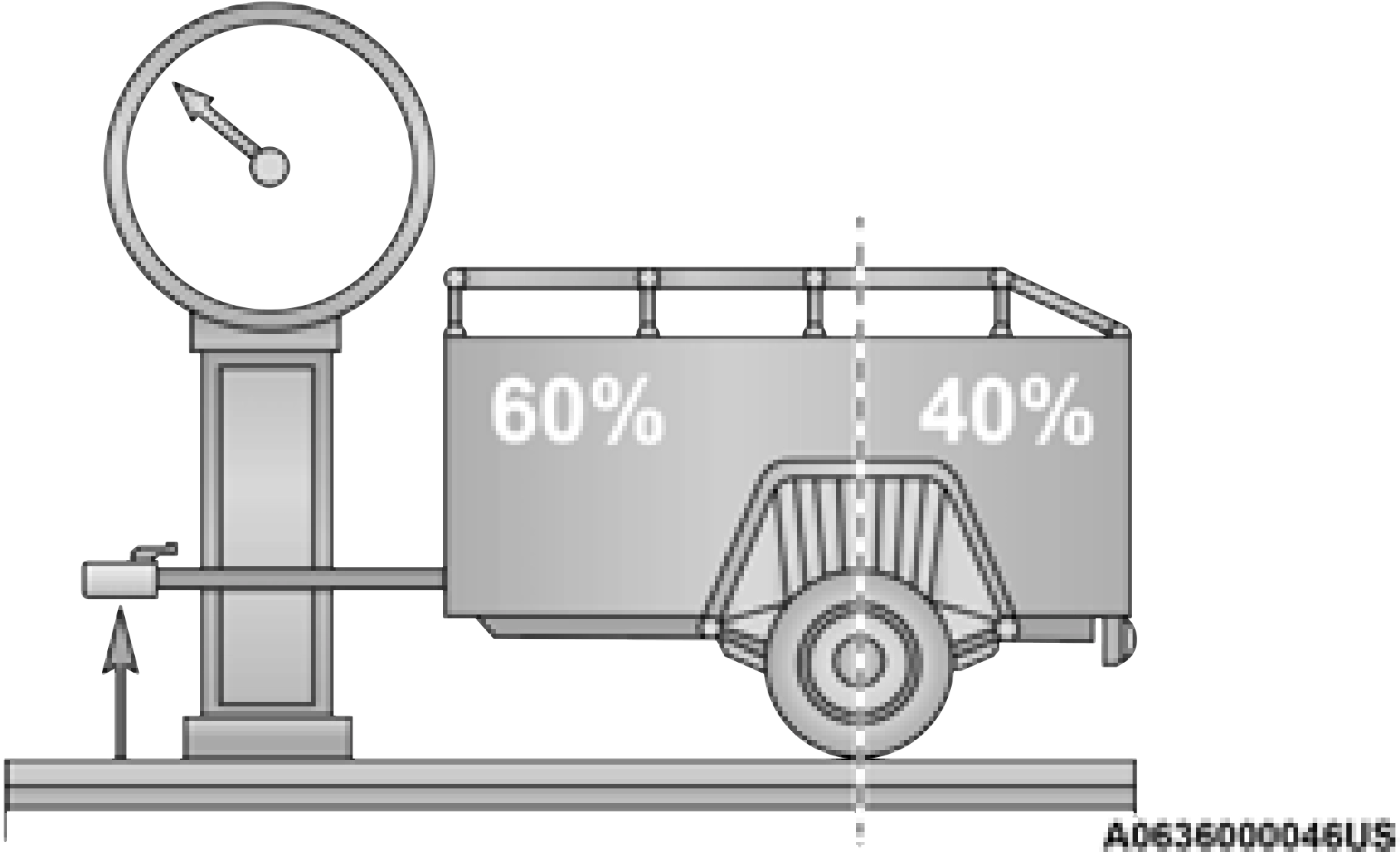
Consider the following items when computing the weight on the rear axle of the vehicle:
Remember that everything put into or on the
trailer adds to the load on your vehicle. Also, additional factory-installed options or
dealer-installed options must be considered as part of the total load on your vehicle. For the maximum combined weight of occupants and cargo for your vehicle page 453.
TOWING REQUIREMENTS
To promote proper break-in of your new vehicle drivetrain components, the following guidelines are recommended.
Perform the maintenance listed in the 4
“Scheduled Servicing” page 394. When
towing a trailer, never exceed the GAWR or GCWR ratings.
Your vehicle may have an Integrated Trailer Brake Module (ITBM) for Electric and Electric Over Hydraulic (EOH) trailer brakes.
This module has been designed and verified with electric trailer brakes and new electric over hydraulic systems. Some previous EOH systems may not be compatible with ITBM.
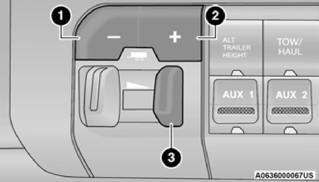
1 — GAIN Adjustment Button 2 — GAIN Adjustment Button
3 — Manual Brake Control Lever
The user interface consists of the following: Manual Brake Control Lever
Slide the manual brake control lever to the left to activate power to the trailer's electric brakes independent of the tow vehicle's brakes. If the manual brake control lever is activated while the brake is also applied, the greater of the two inputs determines the power sent to the trailer
brakes. 4
The trailer and the vehicle’s stop lamps will come on when braking normally with the vehicle brake pedal. Only the trailer stop lamps will come on when the manual brake control lever is applied.
This light indicates the trailer electrical connection status.
If no electrical connection is detected after the ignition is turned on, pushing the GAIN adjustment button or sliding the manual brake control lever will display the GAIN setting for 10 seconds and the “Trailer Brake Status Indicator Light” will not be displayed.
If a fault is detected in the trailer wiring or the Integrated Trailer Brake Module (ITBM), the “Trailer Brake Status Indicator Light” will flash.
Pushing these buttons will adjust the brake control power output to the trailer brakes in
0.5 increments. The GAIN setting can be increased to a maximum of 10 or decreased to a minimum of 0 (no trailer braking).
The GAIN setting is used to set the trailer brake control for the specific towing condition and should be changed as towing conditions change. Changes to towing conditions include trailer load, vehicle load, road conditions and weather.
NOTE:
This should only be performed in a traffic free environment at speeds of approximately 20–25 mph (30–40 km/h).
Repeat steps 8 and 9 until the GAIN setting is at a point just below trailer wheel lockup. If towing a heavier trailer, trailer wheel lockup may not be attainable even with the maximum GAIN setting of 10.
|
Light Electric |
Heavy Electric |
Light EOH |
Heavy EOH |
|
|
Type of Trailer Brakes |
Electric Trailer Brakes |
Electric Trailer Brakes |
Electric Over Hydraulic Trailer Brakes |
Electric Over Hydraulic Trailer Brakes |
|
Load |
*Under 10,000 lb |
*Above 10,000 lb |
*Under 10,000 lb |
*Above 10,000 lb |
* The suggested selection depends and may change depending on the customer preferences for braking performance. Condition of the trailer brakes, driving and road state may also affect the selection.
The trailer brake control interacts with the instrument cluster display. Display messages, along with a single chime, will be displayed when a malfunction is determined in the trailer connection, trailer brake control, or on the trailer page 111.
tric-Over-Hydraulic trailer brake systems. To determine the type of brakes on your trailer and the availability of controllers, check with your trailer manufacturer or dealer.
Whenever you pull a trailer, regardless of the trailer size, stoplights and turn signals on the trailer are required for motoring safety.
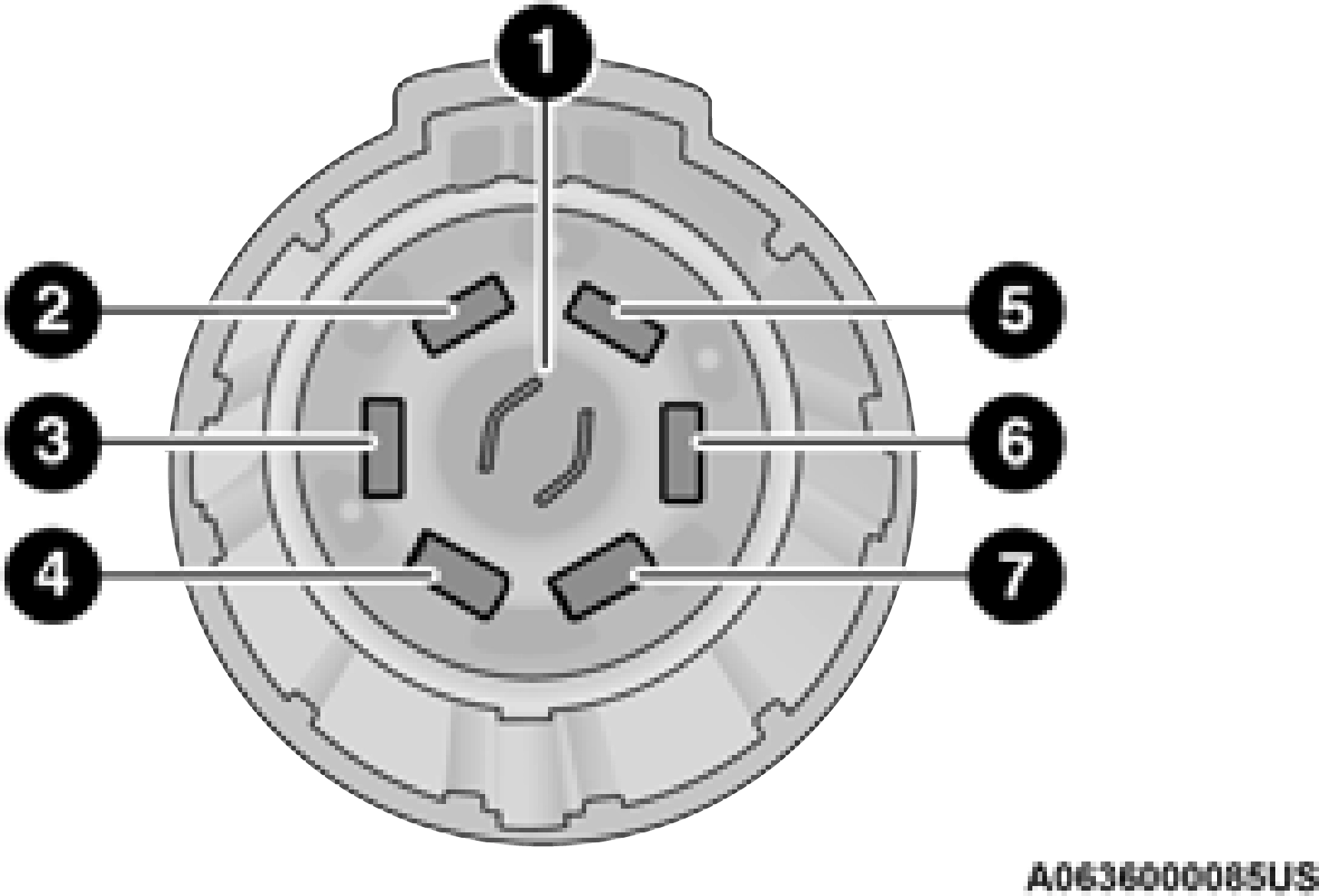
The Trailer Tow Package may include a four- and seven-pin wiring harness. Use a factory approved trailer harness and connector.
Do not cut or splice wiring into the vehicle’s wiring harness.
The electrical connections are all complete to the vehicle but you must mate the harness to a trailer connector. Refer to the following illustrations.
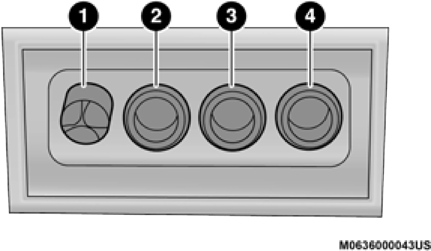
1 — Backup Lamps 2 — Running Lamps 3 — Left Stop/Turn 4 — Ground
This feature will run the trailer lights through a sequence to check the trailer light function. It is available in the instrument cluster under the Trailer Tow menu page 114.
When activated the feature will enable all of the exterior lights sequentially for up to five minutes for time to walk around and verify functionality.
The following exterior lights will remain on for the entirety of the sequence:
During this time the following lights will sequence, each activating for three seconds:
This light check sequence will continue for a total of five minutes.
The sequence will only activate if the following conditions are met:
The sequence will cancel if any of the following conditions occur:
TOWING TIPS
Before setting out on a trip, practice turning, stopping, and backing up the trailer in an area located away from heavy traffic.
The DRIVE range can be selected when towing. The transmission controls include a drive strategy to avoid frequent shifting when towing. However, if frequent shifting does occur while in DRIVE, select TOW/HAUL mode or select a lower gear range (using the Electronic Range Select [ERS] shift control).
Using TOW/HAUL mode or selecting a lower gear range (using the ERS shift control) while operating the vehicle under heavy loading conditions will improve performance and
extend transmission life by reducing excessive shifting and heat build up. This action will also provide better engine braking.
To reduce potential for automatic transmission overheating, activate TOW/HAUL mode when driving in hilly areas, or select a lower gear range (using the Electronic Range Select [ERS]
shift control) on more severe grades. 4
(16 km/h), disengage until you can get back to cruising speed.
To aid in attaching/detaching the trailer from the vehicle, the air suspension system can be used page 177.
The vehicle must remain in the engine running position while attaching a trailer for proper leveling of the air suspension system.
Download Manual