VEHICLE MAINTENANCE
An authorized dealer has the qualified service personnel, special tools, and equipment to perform all service operations in an expert manner. Service Manuals are available which include detailed service information for your vehicle. Refer to these Service Manuals before attempting any procedure yourself.
Intentional tampering with emissions control systems may void your warranty and could result in civil penalties being assessed against you.
ENGINE OIL
Engine Oil Selection — Gasoline Engine
For best performance and maximum protection under all types of operating conditions, the manufacturer only recommends engine oils that are API Certified and meet the requirements of the manufacturer Material Standard MS-12633.
Hemi engines (6.4L) at times can tick right after startup and then quiet down after approxi- mately 30 seconds. This is normal and will not harm the engine. This characteristic can be caused by short drive cycles. For example, if the vehicle is started then shut off after driving a short distance. Upon restarting, you may experi- ence a ticking sound. Other causes could be if
the vehicle is unused for an extended period of time, incorrect oil, extended oil changes or extended idling. If the engine continues to tick or if the Malfunction Indicator Light (MIL) comes on, see the nearest authorized dealer.
For best performance and maximum protection under all types of operating conditions, the manufacturer only recommends engine oils that are API CK-4 certified and meet the requirements of the manufacturer. Use Mopar® or an equivalent oil meeting the manufacturer Material Standard MS-10902. Products meeting Cummins® CES 20081 may also be used. The identification of these engine oils are typically located on the back of the oil container.
 This symbol means that the oil has been certified by the American Petroleum Institute (API). The manufacturer only recommends API Certified engine oils.
This symbol certifies 0W-20, 5W-20, 0W-30, 5W-30 and 10W-30 engine oils.
For diesel engines, oils with a high ash content may produce damaging deposits on cylinder head valves and/or after treatment system damage. A maximum sulfated ash content of
1.00 mass % is recommended for all oil used in the engine.
The same oil change interval is to be followed for synthetic oil as for petroleum-based oil. Also, synthetic oil must meet the same performance specifications as petroleum oil.
You may use synthetic engine oils provided the recommended oil quality requirements are met, and the recommended maintenance intervals for oil and filter changes are followed.
Synthetic engine oils which do not have both the engine oil certification mark and the correct SAE viscosity grade number should not be used.
The manufacturer strongly recommends against the addition of any additives (other than leak detection dyes) to the engine oil. Engine oil is an engineered product and its performance may be impaired by supplemental additives.
Care should be taken in disposing of used engine oil and oil filters from your vehicle. Used oil and oil filters, indiscriminately discarded, can present a problem to the environment. Contact an authorized dealer, service station or governmental agency for advice on how and where used oil and oil filters can be safely discarded in your area.
ENGINE OIL FILTER
The engine oil filter should be replaced with a new filter at every engine oil change.
A full-flow type disposable oil filter should be used for replacement. The quality of replacement filters varies considerably. Only high quality Mopar® certified filters should be used.
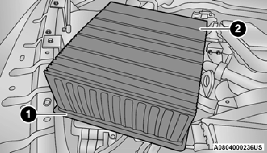
ENGINE AIR CLEANER FILTER
For the proper maintenance intervals
page 394.
The quality of replacement engine air cleaner filters varies considerably. Only high quality filters should be used to ensure most efficient service. Mopar® engine air cleaners are a high quality filter and are recommended.
Inspect engine air cleaner filter for dirt and or debris, if you find evidence of either dirt or
debris you should change your engine air cleaner filter.
When replacing the engine air cleaner filter on vehicles equipped with a 6.4L gasoline engine, replace with a dry (non-oiled) filter only.
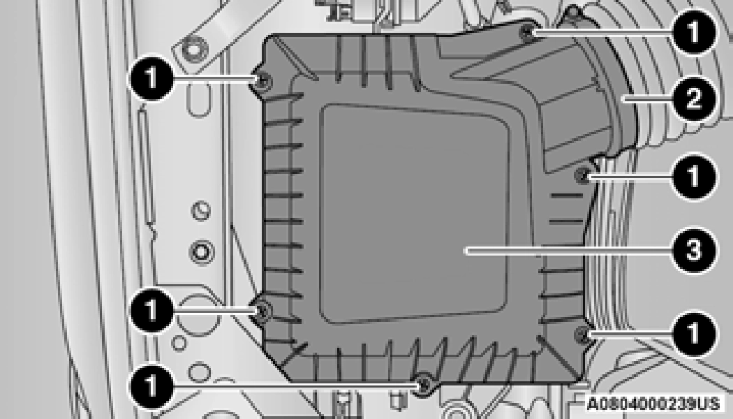
1 — Engine Air Cleaner Filter Cover 2 — Engine Air Cleaner Filter
Inspect and clean the housing if dirt or debris is present before replacing the engine air cleaner filter.
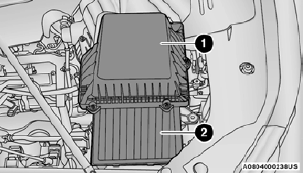
Inspect engine air cleaner filter for dirt and or debris, if you find evidence of either dirt or debris you should change your engine air cleaner filter.
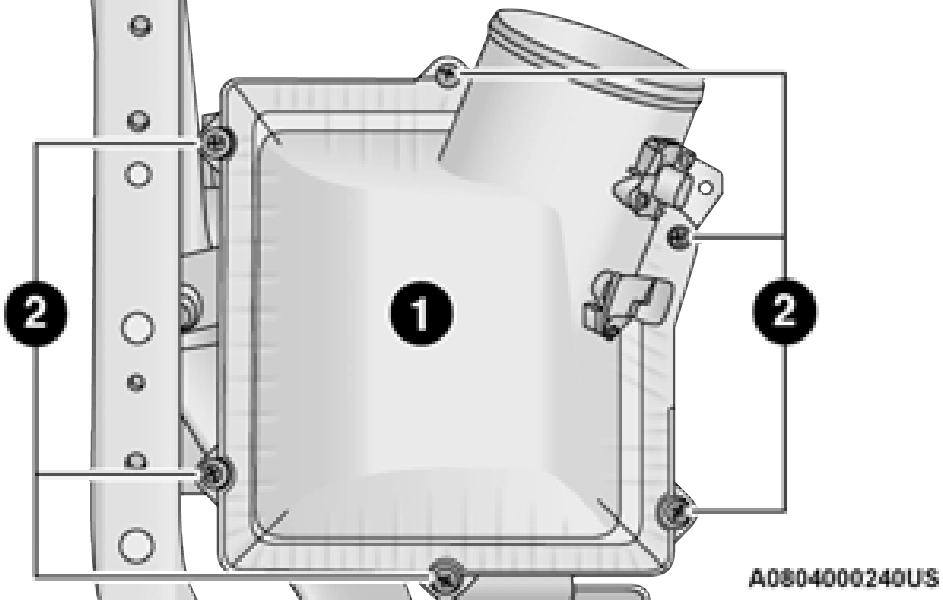
1 — Engine Air Cleaner Filter Cover 2 — Screws
Inspect and clean the housing if dirt or debris is present before replacing the engine air cleaner
filter. 8
AIR CONDITIONER MAINTENANCE
For best possible performance, your air conditioner should be checked and serviced by an authorized dealer at the start of each warm season. This service should include cleaning of the condenser fins and a performance test.
Drive belt tension should also be checked at
this time.
R-134a — (If Equipped)
R-134a Air Conditioning Refrigerant is a hydrofluorocarbon (HFC) that is an
ozone-friendly substance. The manufacturer recommends that air conditioning service be performed by an authorized dealer or other service facilities using recovery and recycling equipment.
Use only manufacturer approved A/C system PAG compressor oil and refrigerants.
R–1234yf Air Conditioning Refrigerant is a hydrofluoroolefin (HFO) that is endorsed by the Environmental Protection Agency and is an ozone-friendly substance with a low
global-warming potential. The manufacturer recommends that air conditioning service be performed by an authorized dealer using recovery and recycling equipment.
Use only manufacturer approved A/C system PAG compressor oil, and refrigerants.
For the proper maintenance intervals
page 394.
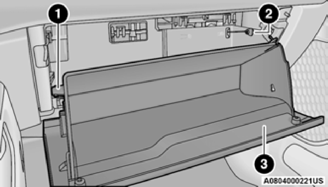
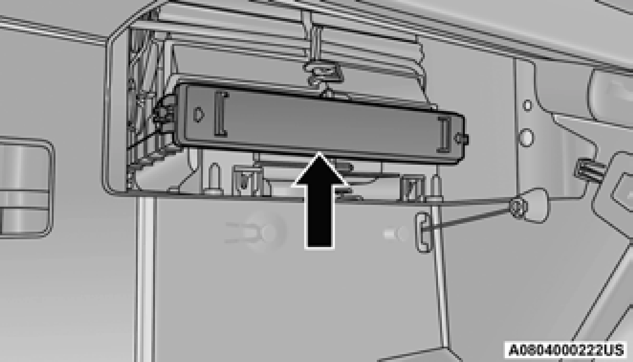
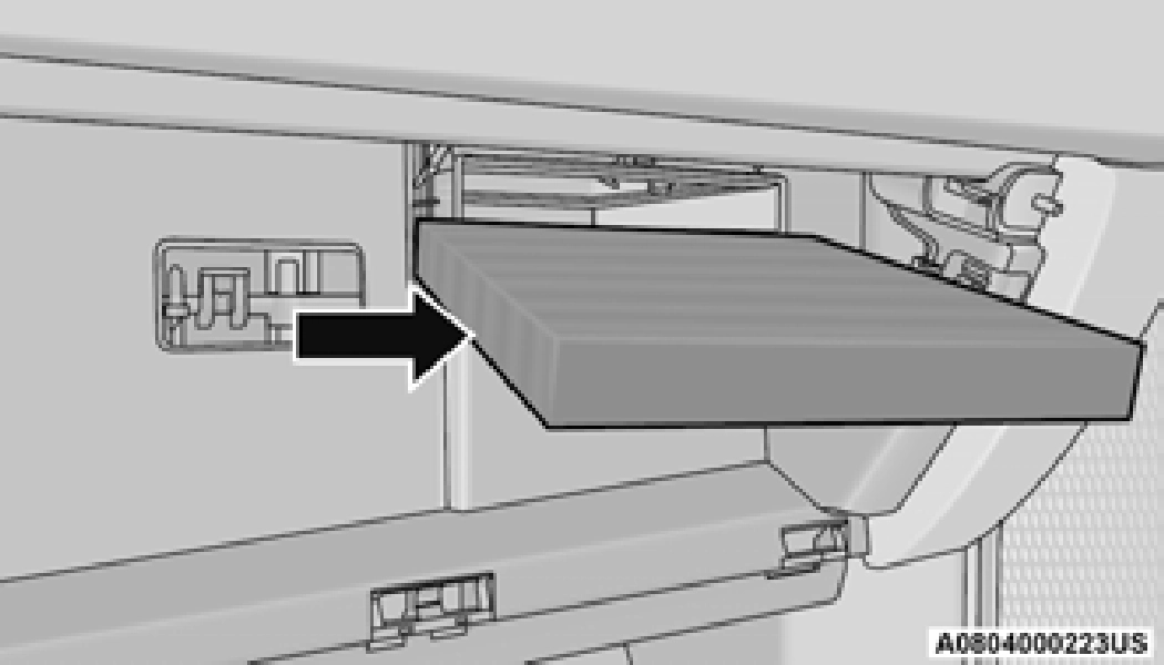
The cabin air filter is located in the fresh air inlet behind the glove compartment. Perform the following procedure to replace the filter:
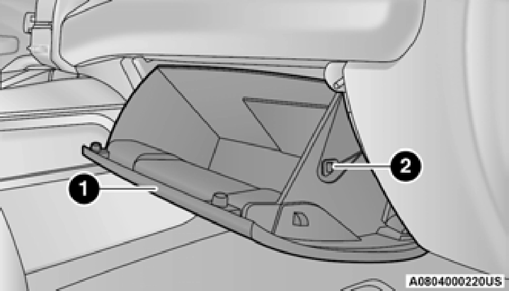
1 — Glove Compartment Door
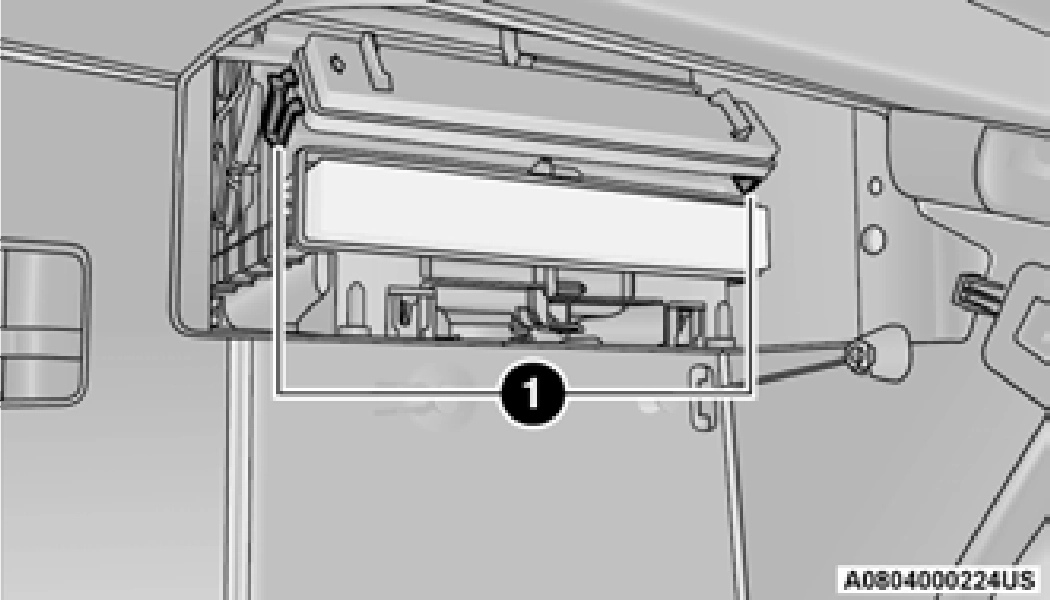
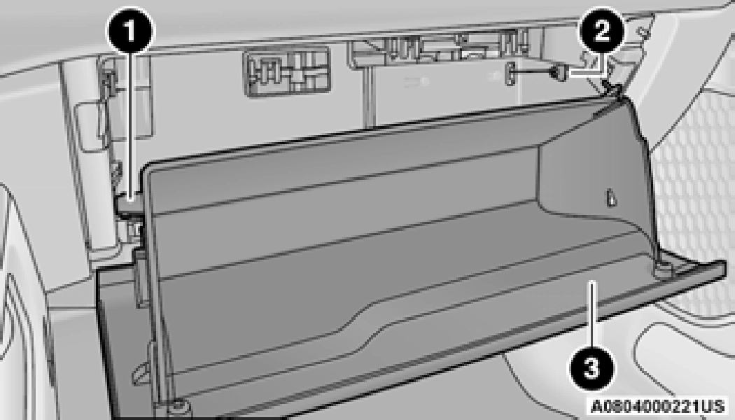
Ensure the glove compartment door hinges and glove compartment travel stops are fully engaged.
ACCESSORY DRIVE BELT INSPECTION
When inspecting accessory drive belts, small cracks that run across ribbed surface of belt from rib to rib, are considered normal. These
are not a reason to replace belt. However, cracks running along a rib (not across) are not normal. Any belt with cracks running along a rib must be replaced. Also have the belt replaced if it has excessive wear, frayed cords or severe glazing.
Conditions that would require replacement:
Some conditions can be caused by a faulty component such as a belt pulley. Belt pulleys should be carefully inspected for damage and proper alignment.
Belt replacement on some models requires the use of special tools, we recommend having your vehicle serviced at an authorized dealer.
DRAINING FUEL/WATER SEPARATOR FILTER — DIESEL ENGINE
There are two fuel filter assemblies. One is located on the driver's side of the engine. The
If water is detected in the water separator while the engine is running, or while the ignition switch is in the ON position, the “Water In Fuel Indicator Light” will illuminate and an audible chime will be heard five times. At this point you should stop the engine and drain the water from both of the filters.
If the “Water In Fuel Indicator Light” remains
on, DO NOT START the engine before you 8
drain water from the fuel filters to avoid
engine damage.
best access to this water drain valve is from
under the hood. The second one is on the under
body, located in front of the rear axle above the drive shaft on pick-up models. The Chassis Cab models second filter location is on the frame behind the front axle. The best access to this water drain valve is from under the vehicle.
If the “Water In Fuel Indicator Light” comes on and a single chime is heard while you are driving, or with the ignition switch in the ON position, there may be a problem with your water separator wiring or sensor. See an authorized dealer for service.
Upon proper draining of the water from both fuel filters, the “Water In Fuel Indicator Light” will remain illuminated for approximately
10 seconds. If the water was drained while the engine was running, the “Water In Fuel Indicator Light” may remain on for approximately three minutes.
Care should be taken in disposing of used fluids from your vehicle. Used fluids, indiscriminately discarded, can present a problem to the environ- ment. Contact an authorized dealer, service station, or government agency for advice on recy- cling programs and for where used fluids and filters can be properly disposed of in your area.
Drain the fuel/water separator filters when the “Water In Fuel Indicator Light” is ON. Within
10 minutes of vehicle shutdown, turn the engine mounted filter drain valve (located on the side of the filter assembly) counterclockwise 1/4 turn, and turn the under body mounted filter drain valve (located on the bottom of the filter assembly) counterclockwise 1 full turn. Then turn the ignition switch to the ON position, and allow any accumulated water to drain. Leave the drain
valve open until all water and contaminants have been removed. When clean fuel is visible, close the drain valve following these guidelines:
Over-compression of the seal due to over-tight- ening of the drain will damage the seal, cause a leak, and require the entire sensor to be replaced.
The sensor drain should not be over-tightened during normal service operations to avoid internal damage and future fuel leaks. The drain should be closed and secured without the use of tools.
If more than a couple ounces/milliliters of fuel have been drained, follow the directions for “Priming If The Engine Has Run Out Of Fuel.”
ENGINE MOUNTED FUEL FILTER REPLACEMENT — DIESEL ENGINE
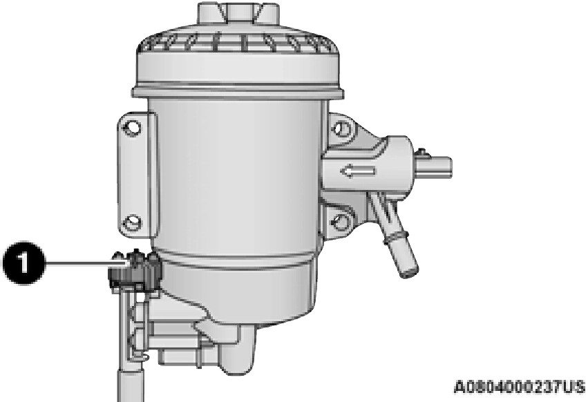
1 — Drain Valve
Do not remove cartridge from bag until you reach this step in order to keep cartridge clean.
22.5 ft lbs (30.5 N.m). Do not overtighten the lid.
UNDERBODY MOUNTED FUEL FILTER REPLACEMENT — DIESEL ENGINE
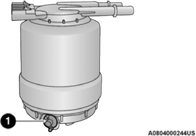
1 — Drain Valve
Water In Fuel (WIF) sensor is re-usable. Service kit comes with new o-ring for filter canister and WIF sensor.
PRIMING IF THE ENGINE HAS RUN OUT OF FUEL — DIESEL ENGINE
The engine may run rough until the air is forced from all the fuel lines.
INTERVENTION REGENERATION STRATEGY — MESSAGE PROCESS FLOW
The Cummins® diesel engine meets all Environmental Protection Agency (EPA) Heavy Duty Diesel Engine Emissions Standards, resulting in one of the lowest emitting diesel engines ever produced.
To achieve these emissions standards, your vehicle is equipped with a state-of-the-art
engine and exhaust system. The engine and exhaust after-treatment system work together to achieve the EPA Heavy Duty Diesel Engine Emissions Standards. These systems are seamlessly integrated into your vehicle and managed by the Cummins® Powertrain Control Module (PCM). The PCM manages engine combustion to allow the exhaust system’s catalyst to trap and burn Particulate Matter (PM) pollutants, with no input or interaction on your part.
If the engine is allowed to idle or the truck is driven on low engine speed drive cycles for more than two hours, the system will automatically enter an emissions operating mode that will increase the engine idle speed to 900 RPM. While in this mode, which is designed to help maintain the Diesel Particulate Filter, the engine idle speed will return to normal when the brake pedal is applied. A small change in engine tone or a slight change in engine performance while accelerating may also be noticeable at speeds below 20 mph (32 km/h). This operating mode may last for up to an hour of idle time, or around 20 minutes of driving time.
Additionally, your vehicle has the ability to alert you to additional maintenance required on your truck or engine page 111.
DIESEL EXHAUST FLUID
Diesel Exhaust Fluid (DEF) sometimes known simply by the name of its active component, UREA—is a key component of selective catalytic reduction (SCR) systems, which help diesel vehicles meet stringent emission regulations. DEF is a liquid reducing agent that reacts with engine exhaust in the presence of a catalyst to convert smog-forming nitrogen oxides (NOx) into harmless nitrogen and water vapor
page 481.
You can receive assistance in locating DEF in the United States by calling 866-RAM-INFO (866-726-4636). In Canada call 1–800–465–2001 (English) or
1–800–387–9983 (French)
You can receive assistance in locating DEF by contacting an authorized dealer.
BODY LUBRICATION
Locks and all body pivot points, including such items as seat tracks, door hinge pivot points and rollers, liftgate, tailgate, decklid, sliding doors and hood hinges, should be lubricated periodically with a lithium-based grease, such as Mopar® Spray White Lube to ensure quiet, easy operation and to protect against rust and wear. Prior to the application of any lubricant, the parts concerned should be wiped clean to remove dust and grit; after lubricating, excess oil and grease should be removed. Particular attention should also be given to hood latching components to ensure proper function. When performing other underhood services, the hood latch, release mechanism and safety catch should be cleaned and lubricated.
The external lock cylinders should be lubricated twice a year, preferably in the Autumn and Spring. Apply a small amount of a high quality lubricant, such as Mopar® Lock Cylinder Lubricant directly into the lock cylinder.
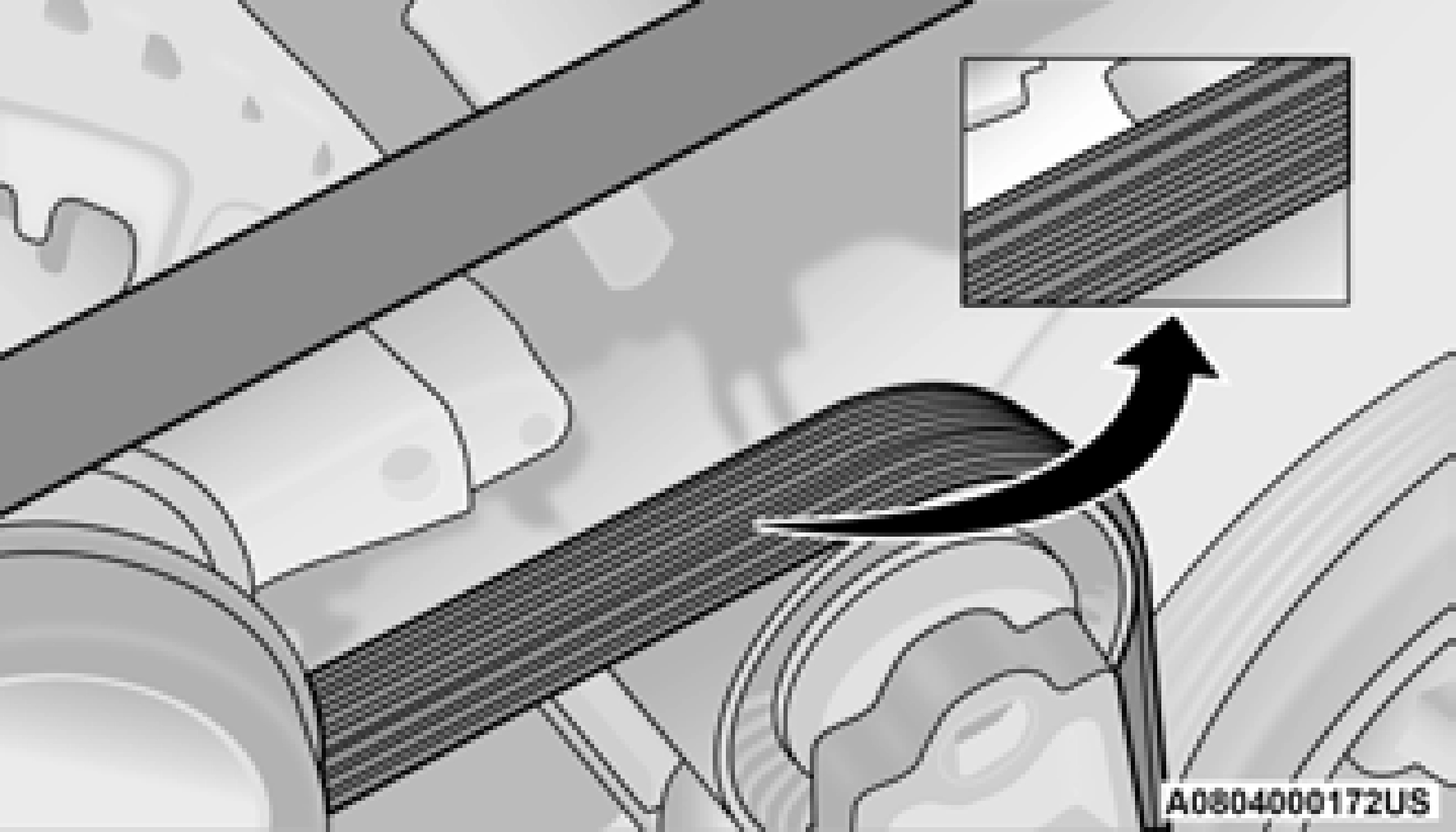
WINDSHIELD WIPER BLADES
Clean the rubber edges of the wiper blades and the windshield periodically with a sponge or soft cloth and a mild nonabrasive cleaner. This will remove accumulations of salt or road film.
Operation of the wipers on dry glass for long periods may cause deterioration of the wiper blades. Always use washer fluid when using the wipers to remove salt or dirt from a dry windshield.
Avoid using the wiper blades to remove frost or ice from the windshield. Keep the blade rubber out of contact with petroleum products such as engine oil, gasoline, etc.
Life expectancy of wiper blades varies depending on geographical area and frequency of use. Poor performance of blades may be present with chattering, marks, water lines or
wet spots. If any of these conditions are present, clean the wiper blades or replace as necessary.
The wiper blades and wiper arms should be inspected periodically, not just when wiper performance problems are experienced. This inspection should include the following points:
If a wiper blade or wiper arm is damaged, replace the affected wiper arm or blade with a new unit. Do not attempt to repair a wiper arm or blade that is damaged.
8
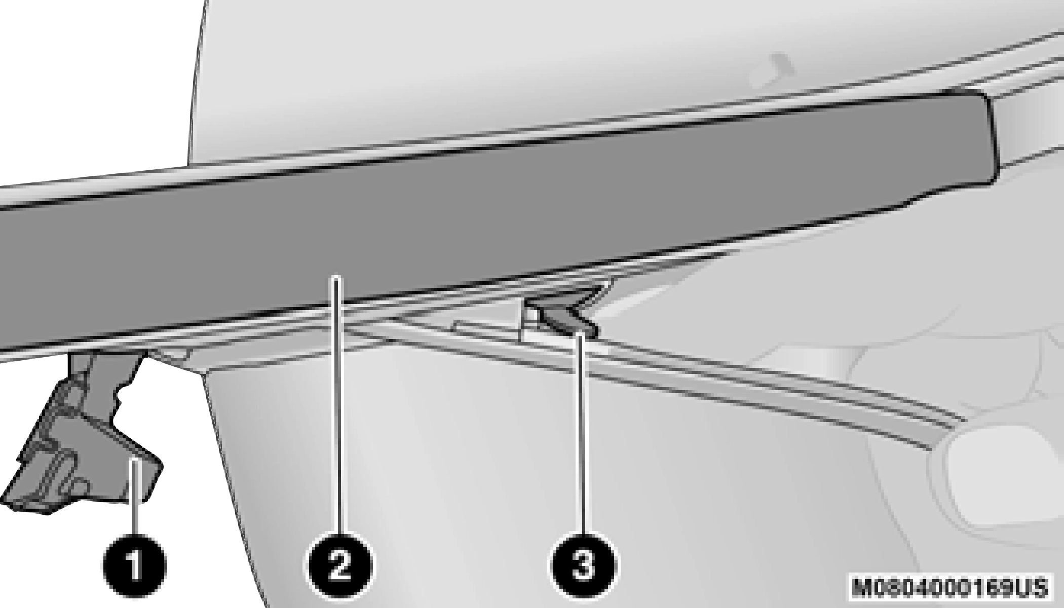
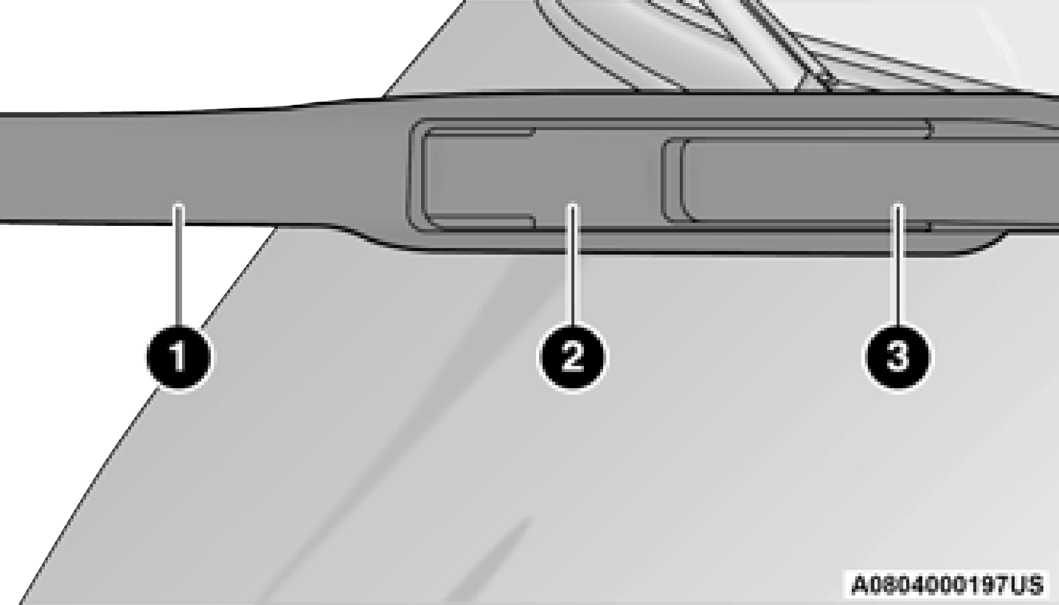
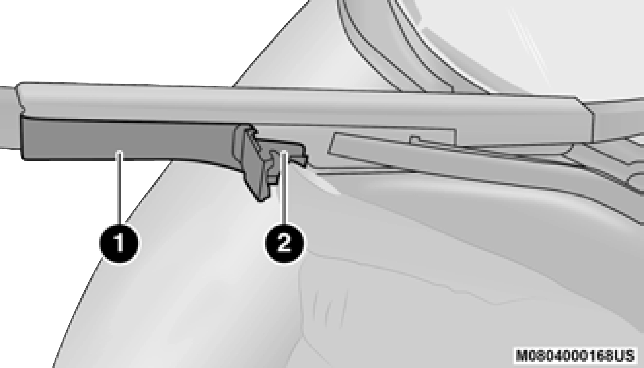
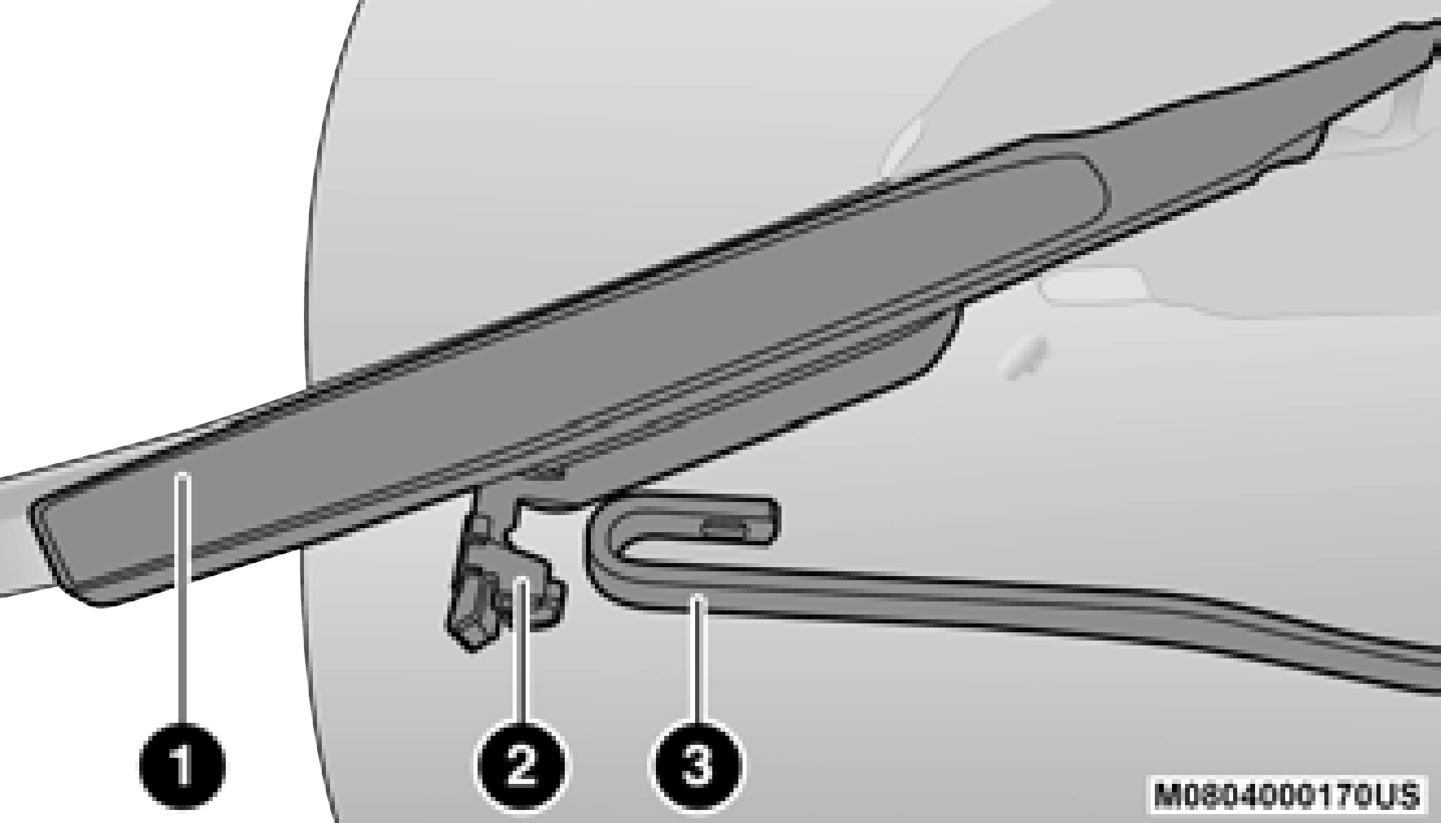
1 — Locking Tab 2 — Wiper
3 — Release Tab
blade down toward the base of the wiper arm and away from the J hook in the end of the wiper arm).
EXHAUST SYSTEM
The best protection against carbon monoxide entry into the vehicle body is a properly maintained engine exhaust system.
If you notice a change in the sound of the exhaust system; or if the exhaust fumes can be detected inside the vehicle; or when the underside or rear of the vehicle is damaged; have an authorized technician inspect the complete exhaust system and adjacent body areas for broken, damaged, deteriorated, or mispositioned parts. Open seams or loose connections could permit exhaust fumes to seep into the passenger compartment. In
addition, have the exhaust system inspected each time the vehicle is raised for lubrication or oil change. Replace as required.
Under normal operating conditions, the catalytic converter will not require maintenance. However, it is important to keep the engine properly tuned to ensure proper catalyst operation and prevent possible catalyst damage.
Intentional tampering with emissions control systems can result in civil penalties being assessed against you.
In unusual situations involving grossly malfunctioning engine operation, a scorching odor may suggest severe and abnormal catalyst overheating. If this occurs, stop the vehicle, turn off the engine and allow it to cool. Service, including a tune-up to manufacturer's specifications, should be obtained immediately.
To minimize the possibility of catalytic converter damage:
periods during very rough idle or malfunc- 8
tioning operating conditions.
(Continued)
COOLING SYSTEM
Check the engine coolant (antifreeze) protection every 12 months (before the onset of freezing weather, where applicable). If the engine coolant is dirty or rusty in appearance,
the system should be drained, flushed and refilled with fresh coolant. Check the front of the A/C condenser or radiator for any accumulation of bugs, leaves, etc. If dirty, clean by gently spraying water from a garden hose vertically down the face of the A/C condenser or the back of the radiator core.
Check the engine cooling system hoses for brittle rubber, cracking, tears, cuts and tightness of the connection at the coolant recovery bottle and radiator. Inspect the entire system for leaks.
DO NOT REMOVE THE COOLANT PRESSURE CAP WHEN THE COOLING SYSTEM IS HOT.
Some vehicles require special tools to add coolant properly. Failure to fill these systems properly could lead to severe internal engine damage. If any coolant is needed to be added to the system please contact an authorized dealer.
If the engine coolant (antifreeze) is dirty or contains visible sediment, have an authorized dealer clean and flush with Organic Additive
Technology (OAT) coolant (conforming to MS.90032).
For the proper maintenance intervals
page 394.
For further information page 481. NOTE:
non-OAT engine coolant is introduced into the cooling system in an emergency, the cooling system will need to be drained, flushed, and refilled with fresh OAT coolant (conforming to MS.90032), by an authorized dealer as soon as possible.
Your vehicle has been built with an improved engine coolant (OAT coolant conforming to MS.90032) that allows extended maintenance intervals. This engine coolant (antifreeze) can be used up to ten years or 150,000 miles (240,000 km) before replacement. To prevent reducing this extended maintenance period, it is important that you use the same engine coolant (OAT coolant conforming to MS.90032) throughout the life of your vehicle.
Please review these recommendations for using Organic Additive Technology (OAT) engine coolant that meets the requirements of the manufacturer Material Standard MS.90032. When adding engine coolant:
The cap must be fully tightened to prevent loss of engine coolant (antifreeze), and to ensure that engine coolant will return to the radiator
from the coolant expansion bottle/recovery 8
tank if so equipped.
The cap should be inspected and cleaned if there is any accumulation of foreign material on the sealing surfaces.
Used ethylene glycol-based coolant (antifreeze) is a regulated substance requiring proper disposal. Check with your local authorities to determine the disposal rules for your community. To prevent ingestion by animals or children, do not store ethylene glycol-based coolant in open containers or allow it to remain in puddles on the ground. If ingested by a child or pet, seek emergency assistance immediately. Clean up any ground spills immediately.
The level of the coolant in the pressurized coolant bottle should be between the “MIN” and “MAX” range on the bottle when the engine is cold.
The radiator normally remains completely full, so there is no need to remove the cap unless checking for coolant freeze point or replacing engine coolant (antifreeze). Advise your service attendant of this. As long as the engine operating temperature is satisfactory, the coolant bottle need only be checked once a month. When additional engine coolant is needed to maintain the proper level, it should be added to the coolant bottle. Do not overfill.
When the vehicle is stopped after a few miles/ kilometers of operation, you may observe vapor coming from the front of the engine compart- ment. This is normally a result of moisture from rain, snow, or high humidity accumulating on the radiator and being vaporized when the ther- mostat opens, allowing hot engine coolant (anti- freeze) to enter the radiator.
If an examination of your engine compartment shows no evidence of radiator or hose leaks, the vehicle may be safely driven. The vapor will soon dissipate.
necessary, install ONLY the correct type ther- mostat. Other designs may result in unsatis- factory engine cooling performance, poor gas mileage, and increased emissions.
CHARGE AIR COOLER — INTER-COOLER
The charge air cooler is positioned below the radiator and the air conditioner condenser. Air enters the engine through the air cleaner and passes through the turbocharger, where it is pressurized. This pressurized air rapidly reaches high temperature. The air is then directed through a hose to the charge air cooler and through another hose to the intake manifold of the engine. The air entering the engine has been cooled by about 50° to 100°F (10° to 38°C). This cooling process enables more efficient burning of fuel resulting in fewer emissions.
To guarantee optimum performance of the system, keep the surfaces of the charge air cooler, condenser and radiator clean and free of debris. Periodically check the hoses leading to and from the charge air cooler for cracks or loose clamps resulting in loss of pressure and reduced engine performance.
BRAKE SYSTEM
In order to ensure brake system performance, all brake system components should be inspected periodically page 394.
The fluid level of the master cylinder should be checked when performing under the hood service or immediately if the brake system warning lamp indicates system failure.
If necessary, add fluid to bring level within the designated marks on the side of the reservoir of the brake master cylinder. Be sure to clean the top of the master cylinder area before removing cap.
With disc brakes the fluid level can be expected to fall as the brake linings wear. However, an unexpected drop in fluid level may be caused by a leak and a system check should be conducted.
For further information page 485.
8
(Continued)
transmissions. Avoid using transmission sealers as they may adversely affect seals.
AUTOMATIC TRANSMISSION
The manufacturer strongly recommends against using any special additives in the transmission. Automatic Transmission Fluid (ATF) is an engineered product and its performance may be impaired by supplemental additives. Therefore, do not add any fluid additives to the transmission. The only exception to this policy is the use of special dyes for diagnosing fluid leaks in six-speed
The fluid level is preset at the factory and does not require adjustment under normal operating conditions. Routine fluid level checks are not required, therefore the transmission has no dipstick. An authorized dealer can check your transmission fluid level using special service tools.
If you notice fluid leakage or transmission malfunction, visit an authorized dealer immediately to have the transmission fluid level checked. Operating the vehicle with an improper fluid level can cause severe transmission damage.
It is best to check the fluid level when the transmission is at normal operating temperature (158-176°F / 70-80°C). This normally occurs after at least 15 miles (25 km) of driving. At normal operating temperature the fluid cannot be held comfortably between the fingertips. You can read the transmission sump temperature in the instrument cluster screen page 111.
Use the following procedure to check the transmission fluid level properly:
the vehicle cannot be driven, see the NOTE and CAUTION below about checking the fluid level at colder temperatures.
the fluid level is low, add fluid through the dipstick tube to bring it to the proper level. Do not overfill. Use ONLY the specified fluid page 485. After adding any quantity of oil through the dipstick tube, wait a minimum of two minutes for the oil to fully drain into the transmission before rechecking the fluid level.
If it is necessary to check the transmission below the operating temperature, the fluid level should be between the two “COLD” (lower) holes on the dipstick with the fluid at 60-70°F / 16-21°C. Only use the COLD region of the dipstick as a rough reference when setting the fluid level after a transmission service or fluid change. Re-check the fluid level, and adjust as required, once the transmission reaches normal operating temperature.
If it is necessary to check the transmission below the operating temperature, the fluid level should be between the two COLD (lower) holes on the dipstick with the fluid at 68-86°F /
20-30°C. Only use the COLD region of the dipstick as a rough reference when setting the fluid level after a transmission service or fluid change. Re-check the fluid level, and adjust as required, once the transmission reaches normal operating temperature.
8
Under normal operating conditions, the fluid installed at the factory will provide satisfactory lubrication for the life of the vehicle.
Routine fluid and filter changes are not required. However, change the fluid and filter if the fluid becomes contaminated (with water, etc.), or if the transmission is disassembled for any reason.
For the proper maintenance intervals
page 394.
In addition, change the fluid and filters if the fluid becomes contaminated (with water, etc.), or if the transmission is disassembled for any reason.
It is important to use the proper transmission fluid to ensure optimum transmission performance and life. Use only the manufacturer’s specified transmission fluid page 485. It is important to maintain the
transmission fluid at the correct level using the
recommended fluid. No chemical flushes should be used in any transmission; only the approved lubricant should be used.
REAR AXLE AND 4X4 FRONT DRIVING AXLE FLUID LEVEL
For normal service, periodic fluid level checks are not required. When the vehicle is serviced for other reasons the exterior surfaces of the axle assembly should be inspected. If gear oil leakage is suspected inspect the fluid level
page 485. This inspection should be made
with the vehicle in a level position.
To check the axle fluid, park the vehicle on a level surface. Take a piece of wire (or zip tie) and make a 90 degree bend two inches from the end of the wire. Insert the wire into the fill
plug hole and use it like a dipstick. Remove the wire and measure from the 90 degree bend to the oil level.
For the 2500 (Non-Power Wagon) axles, the fluid level should be 4/5 in ± 1/4 in (20.3 mm
± 6.4 mm) below the fill hole for the rear axle and it should be 1/4 in ± 1/4 in (6.4 mm ±
6.4 mm) below the fill hole on the front axle.
For the 2500 Power Wagon and all 3500 model axles, the fluid level should be 1/4 in ± 1/4 in (6.4 mm ± 6.4 mm) below the fill hole on the
For the proper maintenance intervals
page 394.
For further information page 485.
The presence of water in the gear lubricant will result in corrosion and possible failure of differ- ential components. Operation of the vehicle in water, as may be encountered in some
off-highway types of service, will require draining and refilling the axle to avoid damage.
Limited-Slip Differentials DO REQUIRE limited slip oil additive (friction modifiers).
Slight noise and mild shuddering may be evident while turning a vehicle with limited slip differential on concrete or dry pavement. These conditions should be considered normal opera- tion of the limited slip differential.
TRANSFER CASE
This fluid level can be checked by removing the filler plug. The fluid level should be to the bottom edge of the filler plug hole with the vehicle in a level position.
For the proper maintenance intervals
page 394.
Use only the manufacturer's recommended fluid page 485.
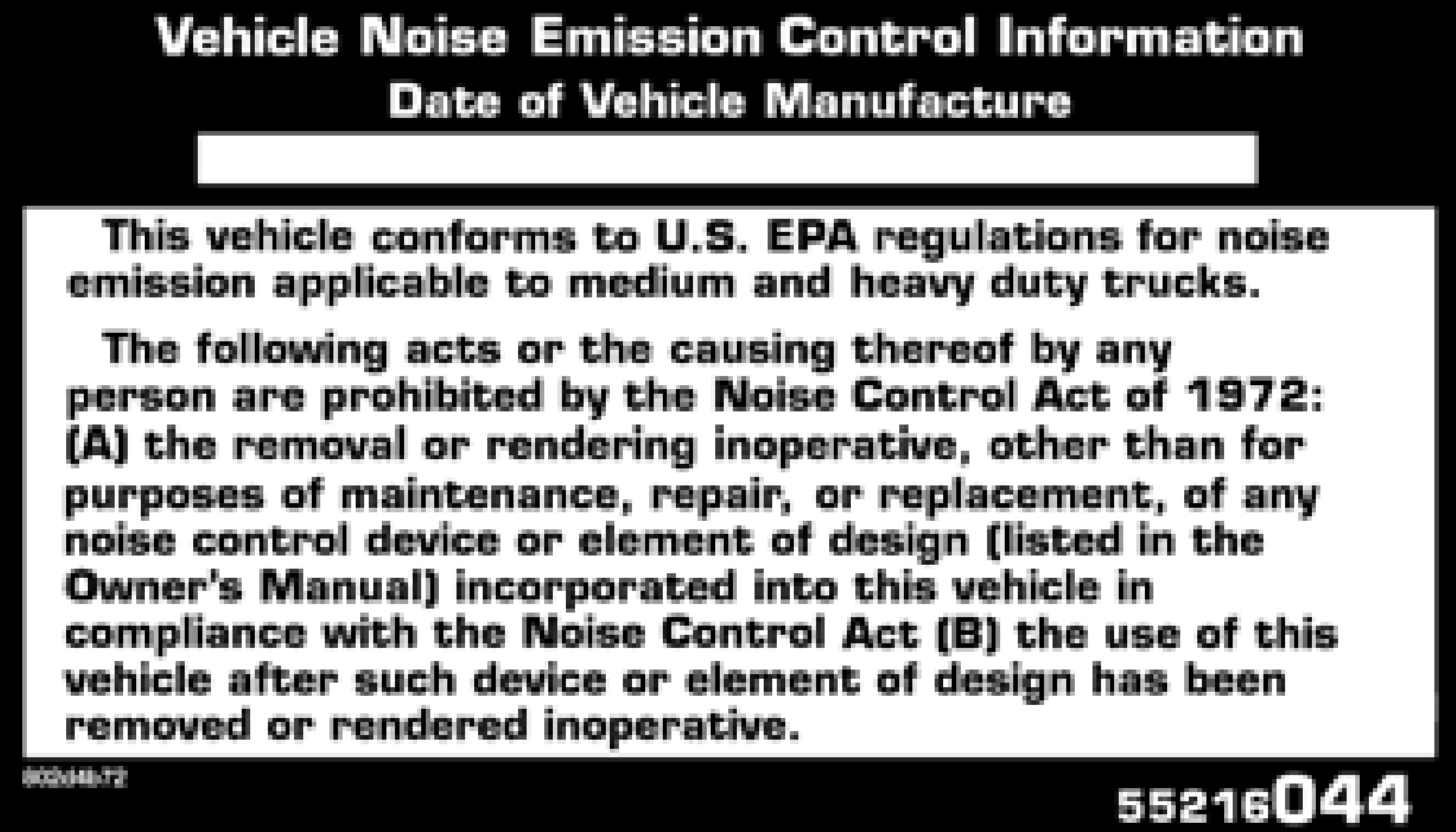
NOISE CONTROL SYSTEM REQUIRED MAINTENANCE & WARRANTY
All vehicles built over 10,000 lbs. (4,535 kg) Gross Vehicle Weight Rating and manufactured for sale and use in the United States are required to comply with the Federal Government's Exterior Noise Regulations.
These vehicles can be identified by the Noise Emission Control Label located in the operator's compartment.
The following maintenance services must be performed every six months or 7,500 miles (12,000 km) whichever comes first, to ensure proper operation of the noise control systems.
In addition, inspection and service should be performed anytime a malfunction is observed or suspected. Proper maintenance of the entire vehicle will help the effectiveness of the noise control systems.
Inspect the entire exhaust system for leaks and damaged parts. Devices such as hangers, clamps, and U-bolts should be tight and in good condition. Damaged components, burned or blown out mufflers, burned or rusted out exhaust pipes should be replaced according to the procedures and specifications outlined in the appropriate service manual.
Inspect air cleaner housing for proper assembly and fit. Make certain that the air cleaner is
properly positioned and that the cover is tight. 8
Check all hoses leading to the air cleaner for
tightness. The air filter element must also be clean and serviced according to the instructions outlined in the Scheduled Maintenance section of this manual.
Federal law prohibits the following acts or the causing thereof: (1) the removal or rendering inoperative by any person, other than for purposes of maintenance, repair, or replacement, of any device or element of design incorporated into any new vehicle for the purpose of noise control prior to its sale or delivery to the ultimate purchaser or while it is in use, or (2) the use of the vehicle after such device or element of design has been removed or rendered inoperative by any person.
Among those acts presumed to constitute tampering are the acts listed below.
system components including the muffler or tailpipe.
The manufacturer warrants that this vehicle as manufactured by the manufacturer, was designed, built and equipped to conform at the time it left the manufacturer's control with all applicable U.S. EPA Noise Control Regulations.
This warranty covers this vehicle as designed, built and equipped by the manufacturer, and is not limited to any particular part, component or system of the vehicle manufactured by the manufacturer. Defects in design, assembly or in any part, component or system of the vehicle as manufactured by the manufacturer, which, at the time it left the manufacturer's control, caused noise emissions to exceed Federal standards, are covered by this warranty for the life of the vehicle.
Maintenance Log and Service Chart (Diesel Engines)
8
FUSES
Also, please be aware that when using power outlets for extended periods of time with the engine off may result in vehicle battery discharge.
(Continued)
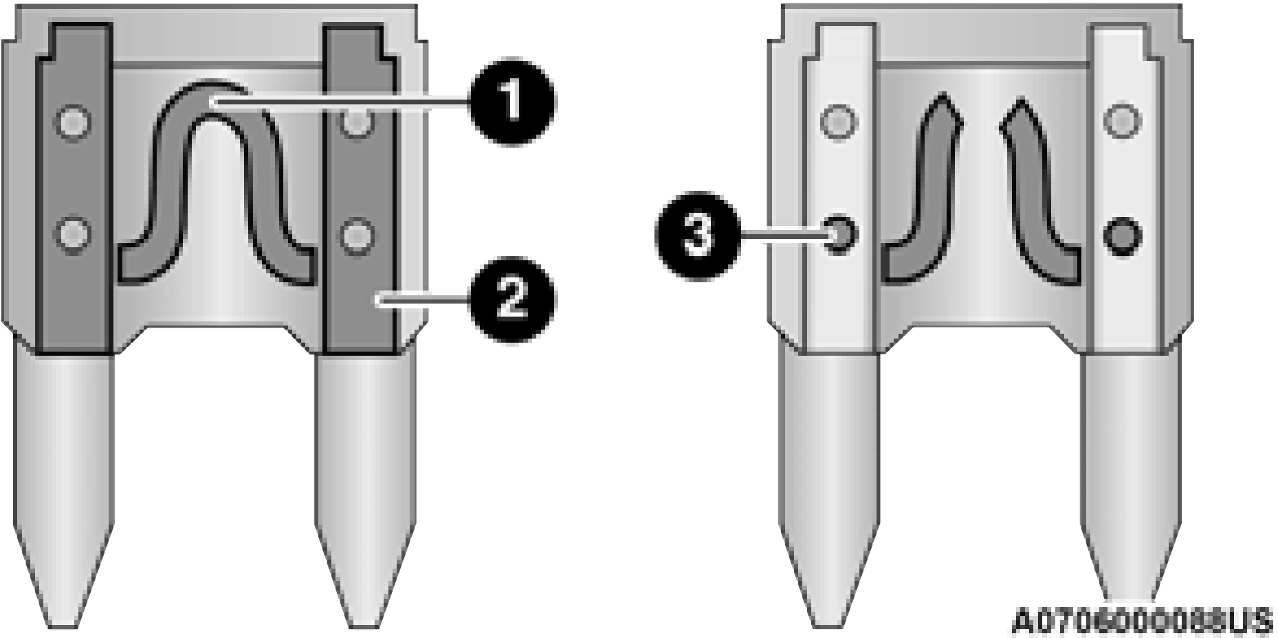
The fuses protect electrical systems against excessive current.
When a device does not work, you must check the fuse element inside the blade fuse for a break/melt.
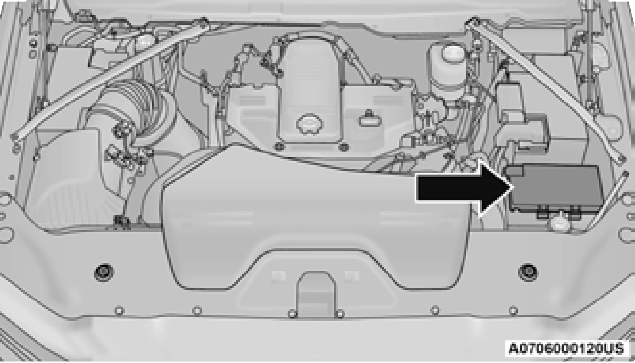
The Power Distribution Center is located in the engine compartment near the battery. This center contains cartridge fuses, micro fuses, relays, and circuit breakers. A description of each fuse and component may be stamped on the inside cover, otherwise the cavity number of each fuse is stamped on the inside cover that corresponds to the following chart.
|
Cavity |
Cartridge Fuse |
Micro Fuse |
Description |
|
F01 |
– |
– |
Spare |
|
F02 |
60 Amp Yellow |
– |
ABS Pump Motor (HD Only) |
|
F03 |
60 Amp Yellow |
– |
Rad Fan * |
|
F04 |
50 Amp Red |
400W Inverter * |
|
Cavity |
Cartridge Fuse |
Micro Fuse |
Description |
|
F05 |
40 Amp Green |
– |
Compressor For Air Suspension * |
|
F06 |
40 Amp Green |
– |
Steering Torque Overlay Module (STOM) |
|
F07 |
40 Amp Green |
– |
Starter Solenoid |
|
F08 |
20 Amp Blue |
– |
NOX Sensor* |
|
F09 |
40 Amp Green |
– |
Diesel / Fuel Heater * |
|
F09 |
30 Amp Pink |
– |
Gas / Brake Vacuum Pump * |
|
F10 |
40 Amp Green |
– |
CBC #2 / Ext Lights |
|
F11 |
40 Amp Green |
– |
Brake System Module (ECU and Valves) |
|
F12 |
40 Amp Green |
– |
CBC #3 / Pwr Locks |
|
F13 |
40 Amp Green |
– |
Blower Motor |
|
F14 |
40 Amp Green |
– |
CBC #4 / Ext Lights |
|
F15 |
30 Amp Pink |
– |
Power Side Steps * |
|
F16 |
30 Amp Pink |
– |
Smart-Bar Module * |
|
F17 |
30 Amp Pink |
– |
Winch Control Module * |
|
F19 |
30 Amp Pink |
– |
Diesel SCR Feed * |
|
F20 |
30 Amp Pink |
– |
Passenger Door Module |
|
F21 |
30 Amp Pink |
– |
Drive Train Control Module |
|
F22 |
20 Amp Blue |
– |
Gas / ECM * |
|
F22 |
25 Amp White |
– |
Diesel PCM * |
|
F23 |
30 Amp Pink |
– |
CBC #1 / Int Light |
|
Cavity |
Cartridge Fuse |
Micro Fuse |
Description |
|
F44 |
– |
10 Amp Red |
Diagnostic Port |
|
F46 |
– |
10 Amp Red |
Upfitters Relay Coil * |
|
F47 |
– |
– |
Spare |
|
F48 |
– |
– |
Spare |
|
F49 |
– |
10 Amp Red |
IP Cluster / CSG |
|
F50 |
– |
20 Amp Yellow |
Air Suspension Control Module * |
|
F51 |
– |
10 Amp Red |
Ignition Node Module / Keyless Ignition Node Module, Radio Frequency Hub Module / Electric Steering Column Lock * |
|
F52 |
– |
5 Amp Tan |
Battery Sensor |
|
F53 |
– |
20 Amp Yellow |
Trailer Tow – Left Turn/Stop Lights * |
|
F54 |
– |
20 Amp Yellow |
Non Memory Adjustable Pedals * |
|
F55 |
– |
– |
Spare |
|
F56 |
– |
10 Amp Red |
Fuel Vapor Blocker Valve * |
|
F57 |
– |
20 Amp Yellow |
TCM / PCM / Solenoid Trans Pressure SW (RFE Trans Only) * |
|
F58 |
– |
10 Amp Red |
Bed Lighting (LED) * |
|
F60 |
– |
— |
Spare |
|
F61 |
– |
10 Amp Red |
NH3 Sensor / PM Sensor * |
|
F62 |
– |
10 Amp Red |
Air Conditioning Clutch |
|
F63 |
– |
20 Amp Yellow |
Ignition Coils / CAPS |
|
Cavity |
Cartridge Fuse |
Micro Fuse |
Description |
|
F83 |
– |
– |
Spare |
|
F84 |
– |
15 Amp Blue |
ASBM / HVAC / ICS / Rear Heated Seat Switches |
|
F85 |
– |
10 Amp Red |
Airbag Module |
|
F86 |
– |
10 Amp Red |
Airbag Module |
|
F87 |
– |
10 Amp Red |
Air Suspension / ITBM / Steering Column Control Module / MOD Gateway CAN-C Trailer TPM |
|
F88 |
– |
15 Amp Blue |
Instrument Panel Cluster |
|
F90/F91 |
– |
20 Amp Yellow |
Power Outlet / Batt Power Outlet / Acc |
|
F92 |
– |
– |
Spare |
|
F93 |
– |
– |
Spare |
|
F94 |
– |
10 Amp Red |
Shift-By-Wire / Transfer Case Switch / Module TPM Trailer / Module Gateway Can-C Trailer TPM |
|
F95 |
– |
10 Amp Red |
Rearview Camera / Park Assist / CHMSL Camera / Blind Spot Sensor / Surround View Camera |
|
F96 |
– |
10 Amp Red |
Trailer Camera * |
|
F97 |
– |
20 Amp Yellow |
Front Heated Seat Passenger * |
|
F98 |
– |
20 Amp Yellow |
Front Heated Seat Driver * |
|
F99 |
– |
10 Amp Red |
HVAC / In-Car Temperature Sensor / CSG MOD |
|
F100 |
– |
10 Amp Red |
Upfitters Box Feed * |
|
F101 |
– |
20 Amp Yellow |
Rear Heated Seat Right * |
|
Cavity |
Cartridge Fuse |
Micro Fuse |
Description |
|
F102 |
– |
20 Amp Yellow |
Rear Heated Seat Left / Run RLY #3 Coil * |
|
F103 |
– |
10 Amp Red |
HeadLamp AFLS * |
|
F104 |
– |
20 Amp Yellow |
UCI Port / USB Rear |
* If Equipped
|
CAUTION! |
|
When installing the power distribution center cover, it is important to ensure the cover is properly positioned and fully latched. Failure to do so may allow water to get into the power distribution center and possibly result in an electrical system failure.
When replacing a blown fuse, it is important to use only a fuse having the correct amperage rating. The use of a fuse with a rating other than indi- cated may result in a dangerous electrical system overload. If a properly rated fuse continues to blow, it indicates a problem in the circuit that must be corrected.
|
See an authorized dealer for LED bulb replacement.
All of the inside bulbs are brass or glass-wedge base. Aluminum base bulbs are not approved.
|
Interior Bulbs |
|
|
Bulb Name |
Bulb Number |
|
Overhead Console Lamps |
TS 212–9 |
|
Dome Lamp |
7679 |
|
For lighted switches, see an authorized dealer for replacement instructions. |
|
Exterior Bulbs |
|
|
Bulb Name |
Bulb Number |
|
Low Beam (Halogen Reflector Headlamp) |
H11LL |
|
High Beam (Halogen Reflector Headlamp) |
9005LL |
|
Low & High Beam (LED Reflector Headlamp) |
LED (Serviced at an authorized dealer) |
|
Low & High Beam (LED Projector Headlamp) |
LED (Serviced at an authorized dealer) |
|
Turn Signal / Front Position (Halogen Reflector Headlamp) |
7444NA |
|
Turn Signal (LED Projector Headlamp) |
LED (Serviced at an authorized dealer) |
|
Front Position (LED Headlamps) |
LED (Serviced at an authorized dealer) |
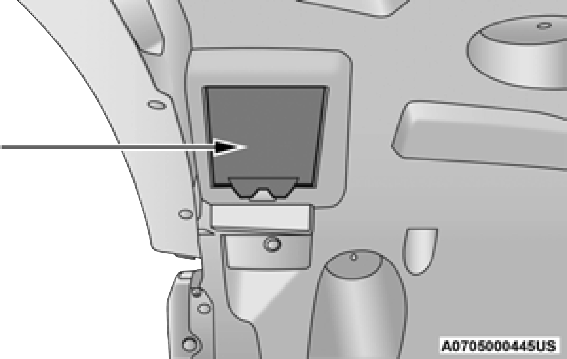
Base Quad: Low Beam Headlamp, High Beam Headlamp, Front Park And Turn — If Equipped
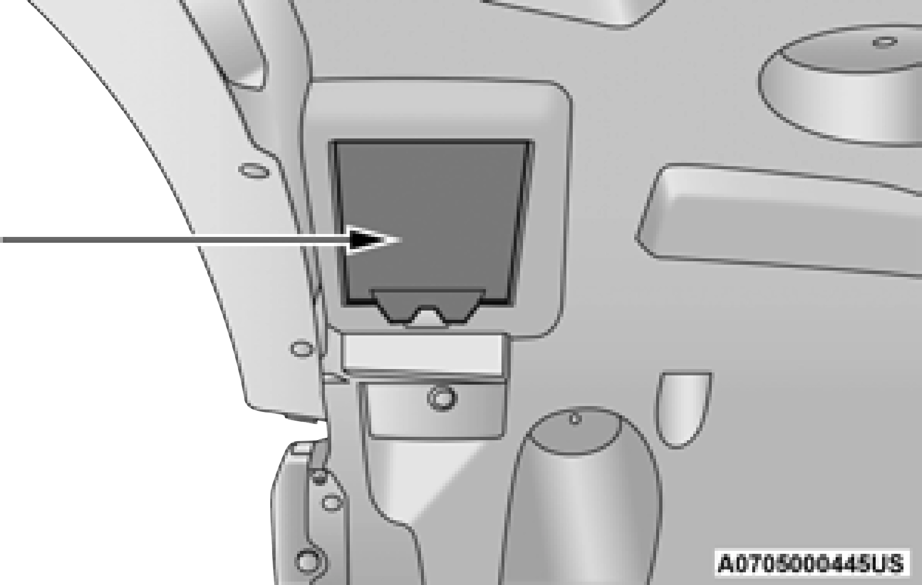
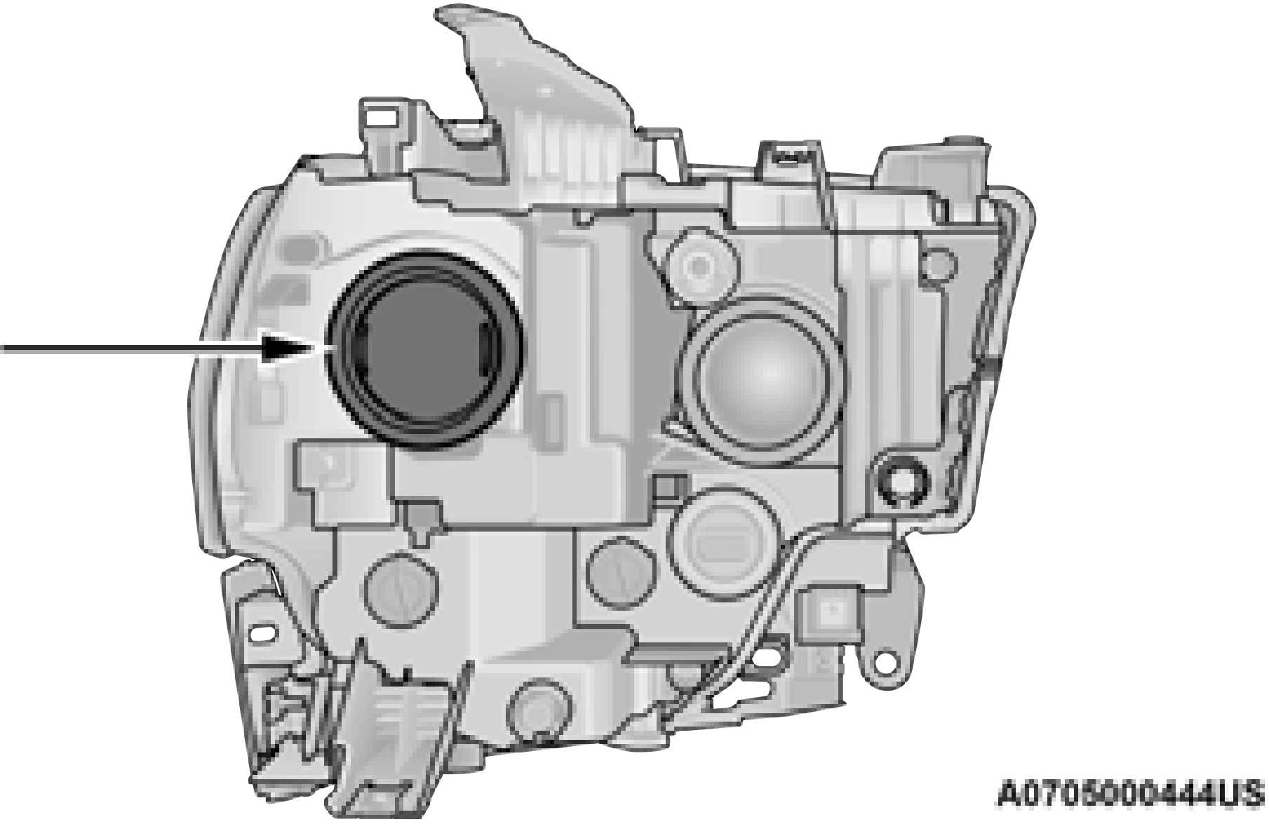
Low Beam
See below steps to replace:
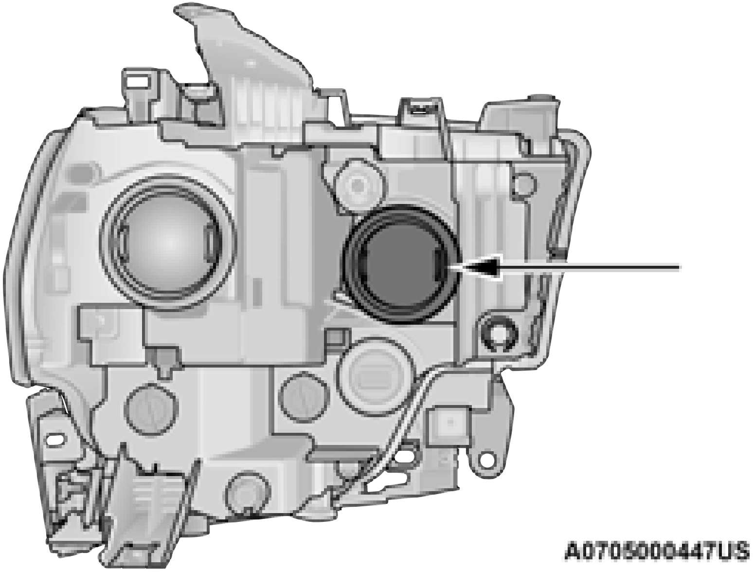
See below steps to replace:
Outer Front Park And Turn See below steps to replace:
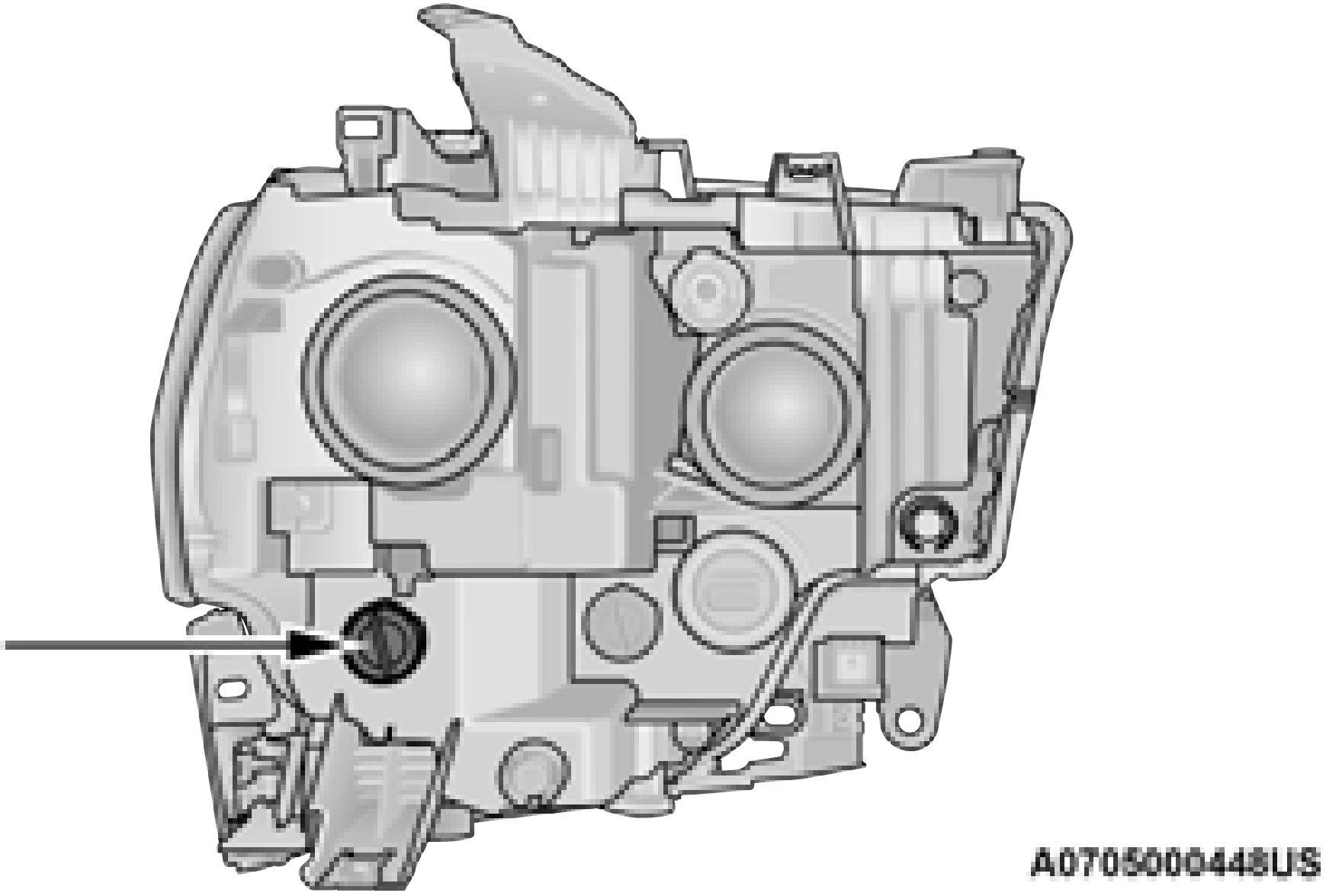
twisting.
Fog Lamps — If Equipped
Please see an authorized dealer for service on LED and Halogen front fog lamps.
See below steps to replace:
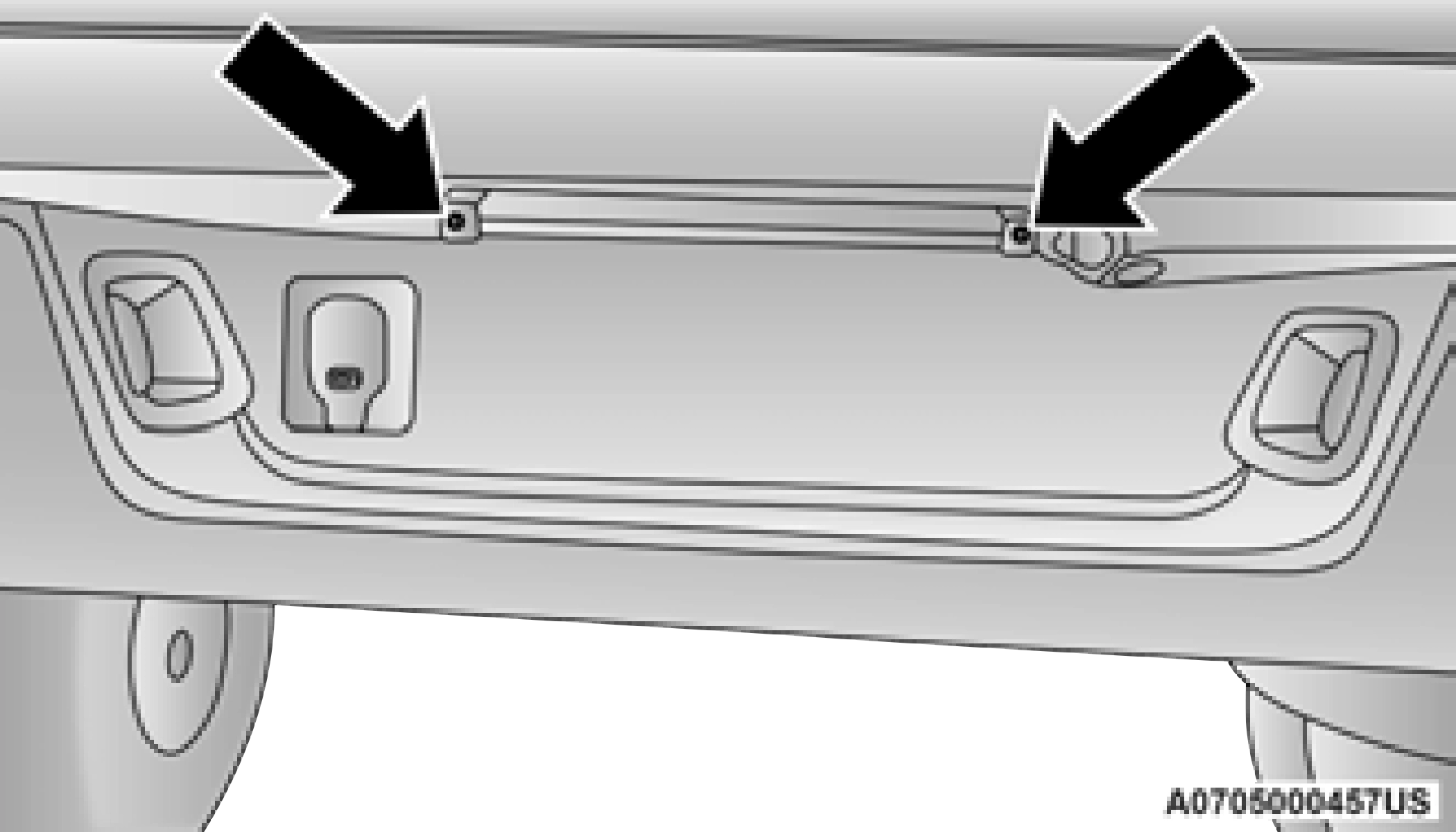
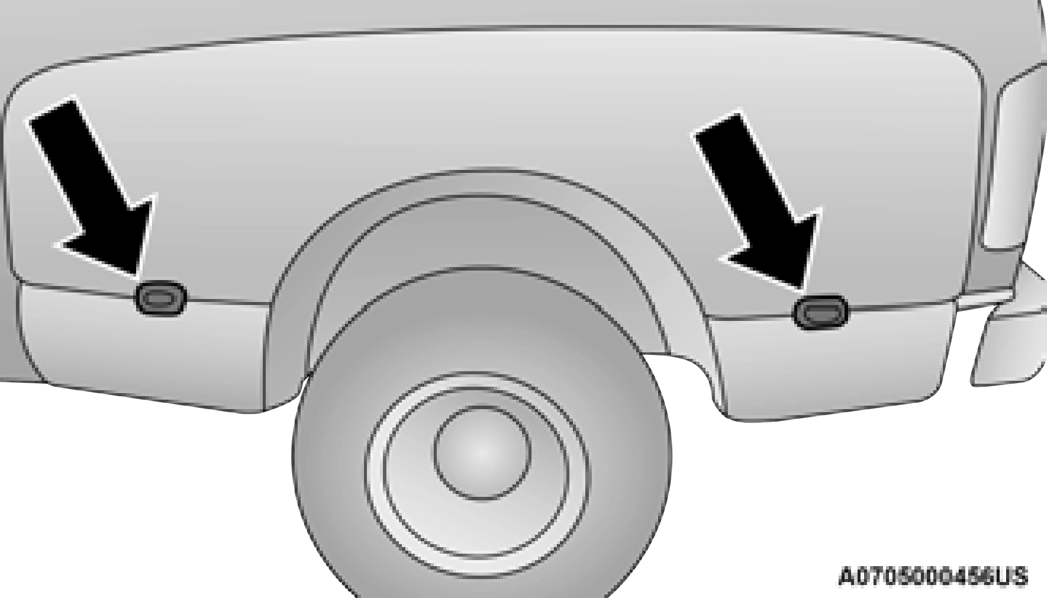
Rear Tail/Stop, Turn Signal And Backup Lamps See below steps to replace:
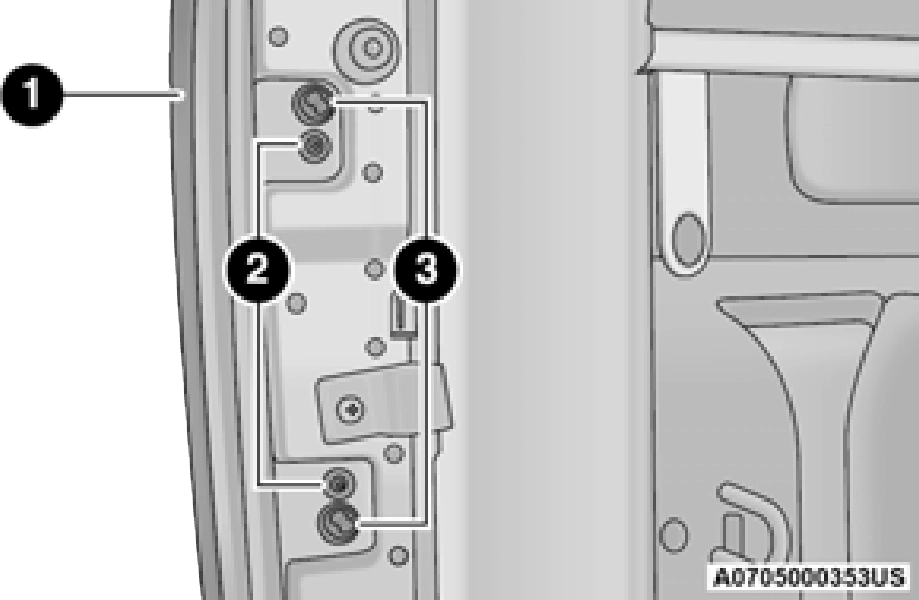
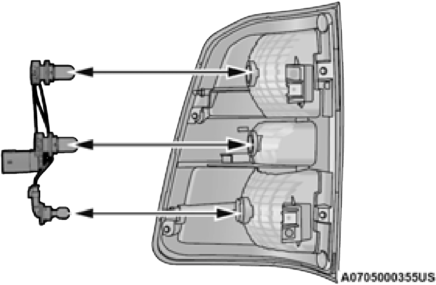
4. Pull the bulb straight out from the housing.
1 — Tail Lamp 2 — Screws
3 — Fasteners
6. Reverse the procedure to install the bulb and housing.
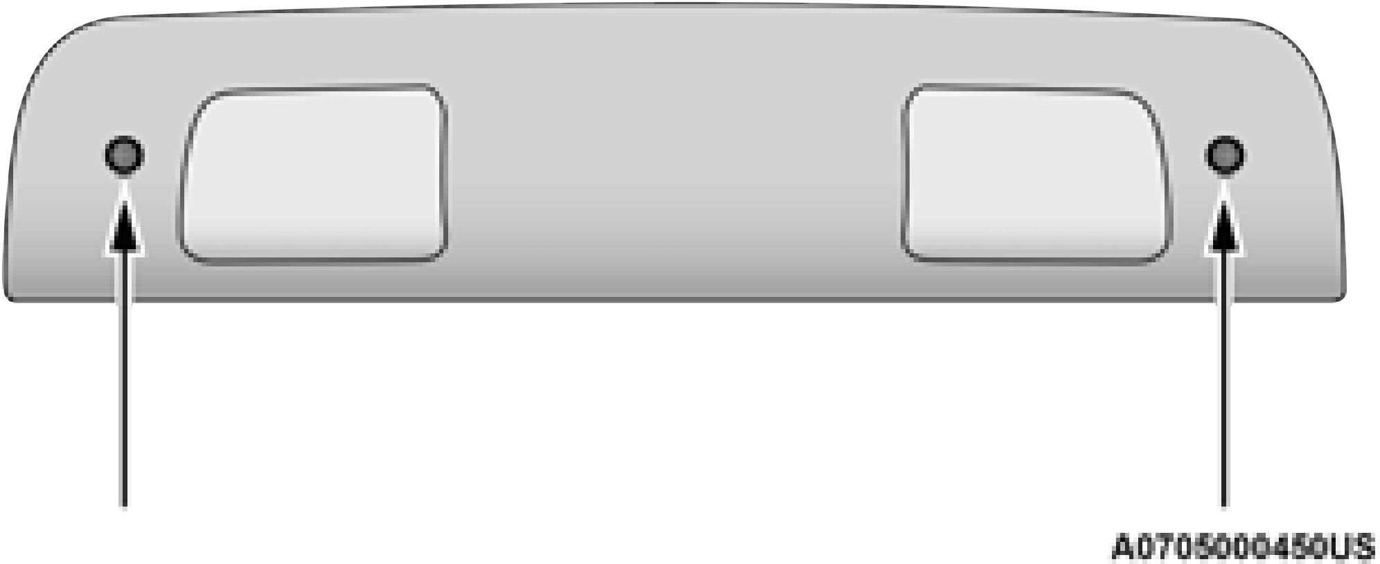
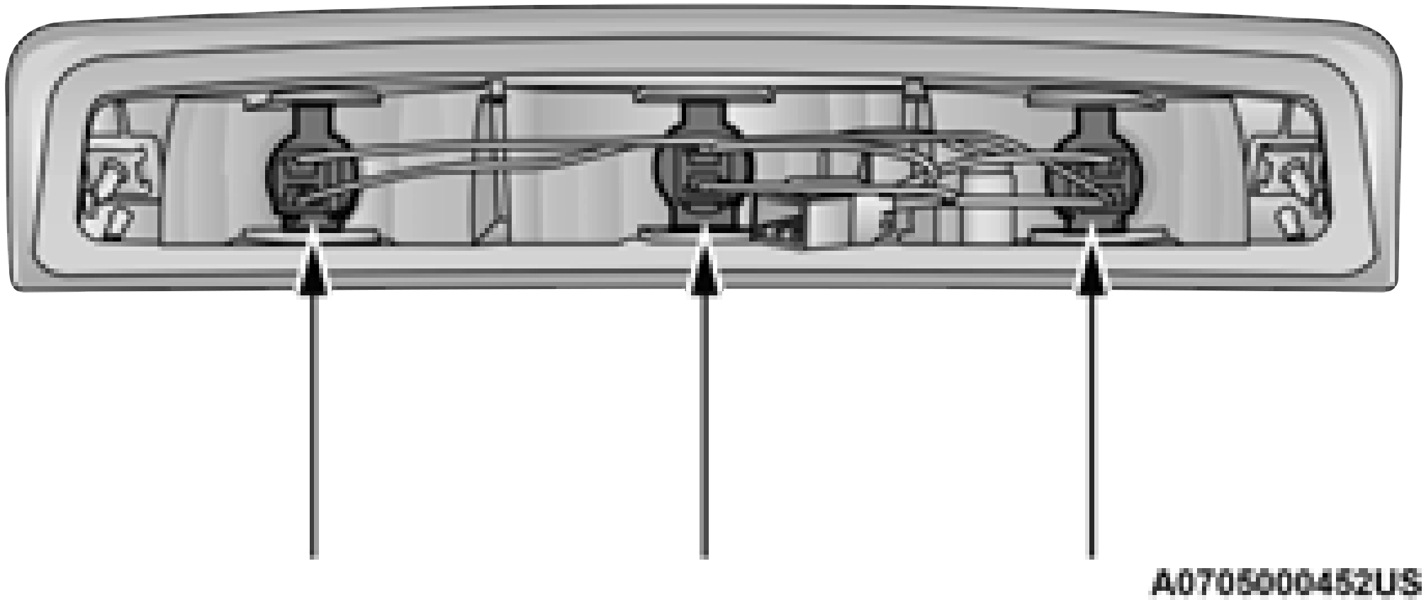
Center High Mounted Stop Lamp (CHMSL) With Cargo Lamp
See below steps to replace:
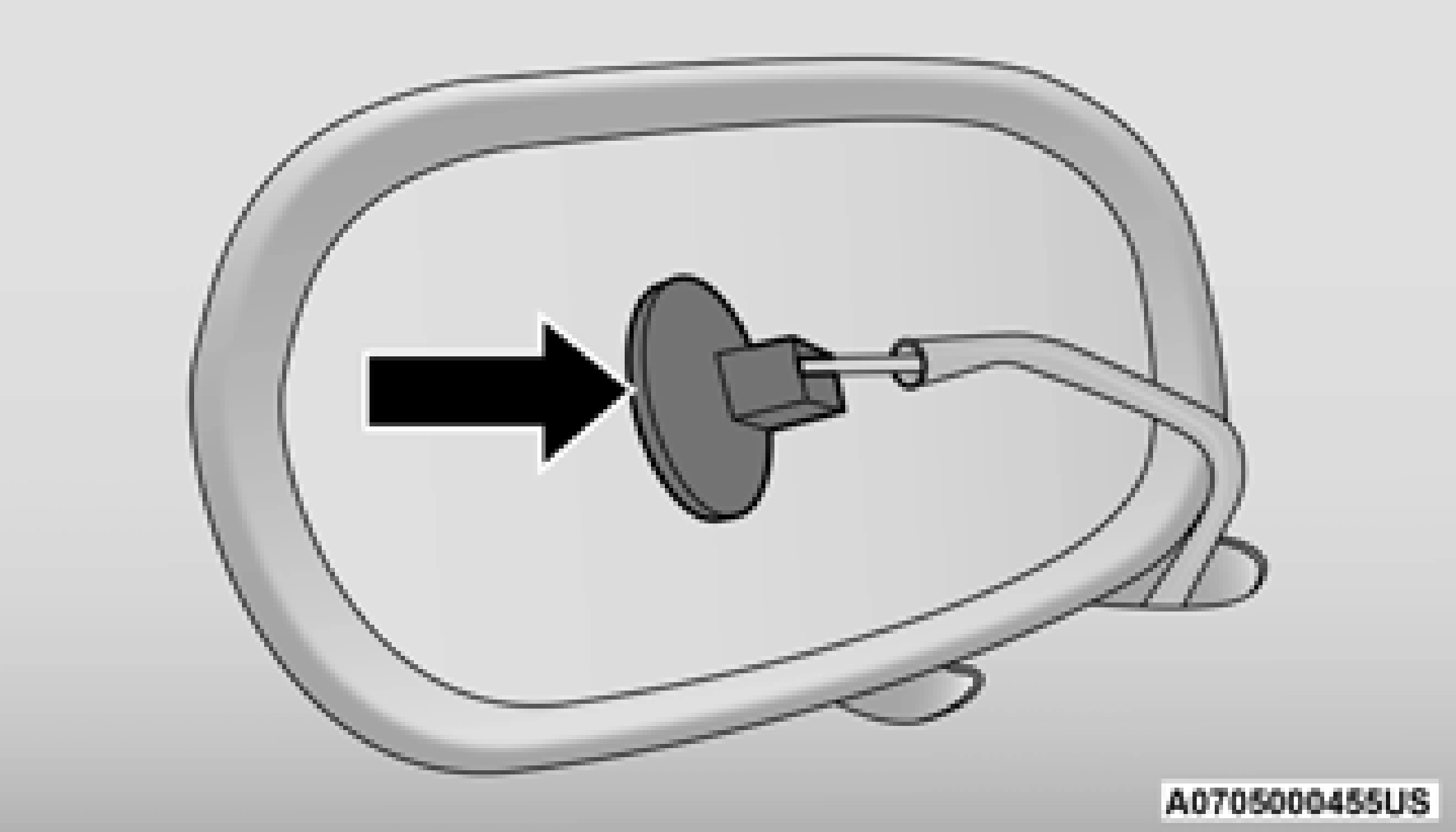
Cab Top Clearance Lamps — If Equipped See below steps to replace:
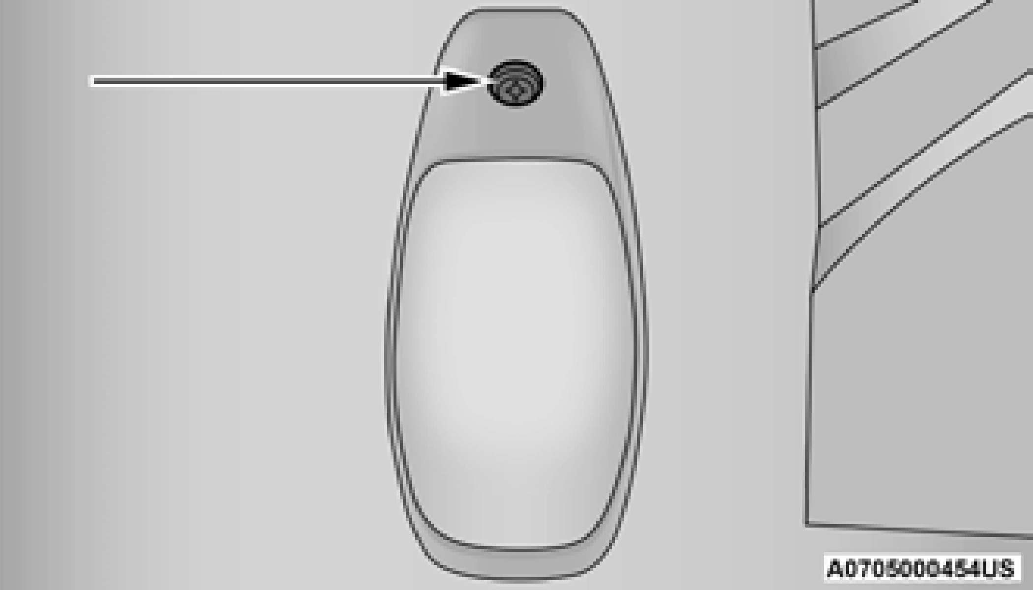 Remove the screws from the top of the lamp.
8
Rear Lamp Bar ID Marker (Dual Rear Wheels)
— If Equipped
See below steps to replace:
Side Marker Lamps (Dual Rear Wheels) — If Equipped
See below steps to replace:
Download Manual