PICKUP BOX
The pickup box has many features designed for utility and convenience.
4 — Anchors
If you are installing a Toolbox, Ladder Rack or Headache Rack at the front of the Pickup Box, you must use Mopar® Box Reinforcement Brackets that are available from an authorized dealer.
You can carry wide building materials (sheets of plywood, etc.) by building a raised load floor. Place lumber across the box in the indentations
There are stampings in the sheet metal on the inner side bulkheads of the box in front of and behind both wheel housings. Place wooden boards across the box from side to side to create separate load compartments in the pickup box.
There are four tie-down cleats bolted to the lower sides of the pickup box that can sustain loads up to 1000 lb (450 kg) total.
CARGO CAMERA — IF EQUIPPED
Your vehicle may be equipped with the Cargo Camera that allows you to see an image of the inside of the pickup box. The image will be displayed in the Uconnect screen.
The Cargo Camera is located in the bottom center area of the Center High Mounted Stop Lamp (CHMSL).
 A touchscreen button to indicate the current active camera image being displayed is made available whenever the Cargo Camera image is displayed.
 A touchscreen button to switch the display to rear view camera image is made available whenever the Cargo Camera image is displayed.
A touchscreen button "X" to disable display of the camera image is made available when the vehicle is not in REVERSE gear.
A display timer is initiated when the Cargo Camera image is displayed. The image will continue to be displayed until the display timer exceeds 10 seconds and the vehicle speed is above 8 mph (13 km/h) or the touchscreen button "X" to disable display of the Cargo Camera image is pressed.
The Dynamic Centerline feature provides an overlay on the Cargo Camera display screen that aligns to the center of the pickup box to aid in hooking up a fifth wheel camper or gooseneck trailer. The centerline auto aligns to the center of the pickup box, and can also be manually adjusted. The centerline will adjust in response to steering angle inputs, and will not obstruct the gooseneck receiver or an approaching trailer gooseneck in the camera feed.
The Dynamic Centerline feature can be activated through the Uconnect Settings by pressing the Cargo Camera soft button, followed by the “Adjust Centerline” soft button on the touchscreen.
If the Dynamic Centerline feature is turned on, the overlay will display anytime the Cargo Camera image is displayed.
Follow the steps below to manually adjust the centerline:
The Dynamic Centerline feature will automatically be deactivated whenever the Cargo Camera display is deactivated. It can also be manually deactivated through the Uconnect Settings page 258.
Turning Cargo Camera On Or Off — With Uconnect 4C/4C NAV
Once initiated by the "Cargo Camera" button, the Cargo Camera image will be displayed until the vehicle speed remains below 8 mph
(13 km/h) and the 10 second timer runs out. The image may be deactivated by pressing the "X" soft button, placing the ignition in the OFF position, placing the gear selector in PARK, or pressing the image defeat “X” button. On deac- tivation, the previous selected screen will appear.
BED RAIL TIE-DOWN SYSTEM — IF EQUIPPED
This feature is only available for vehicles equipped with a RamBox.
There are two adjustable cleats on each side of
the bed that can be used to assist in securing 2
cargo.
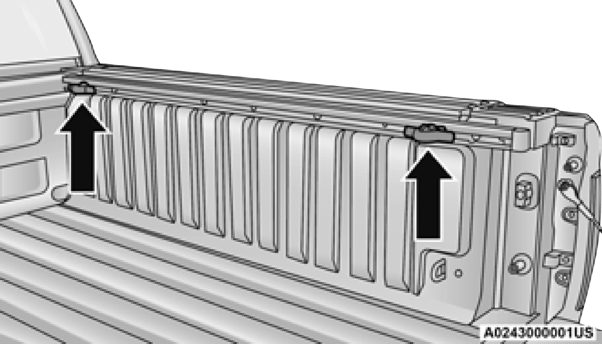
Each cleat must be located and tightened down in one of the detents, along either rail, in order to keep cargo properly secure.
To move the cleat to any position on the rail, turn the nut counterclockwise several turns. Then pull out on the cleat and slide it to the
detent nearest the desired location. Make sure the cleat is seated in the detent and tighten the nut.
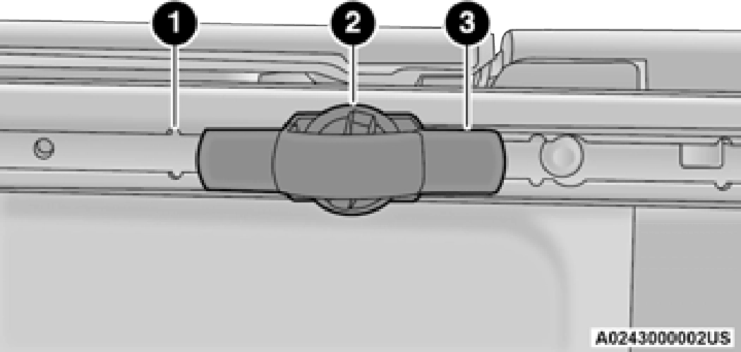
1 — Utility Rail Detent 2 — Cleat Retainer Nut 3 — Utility Rail Cleat
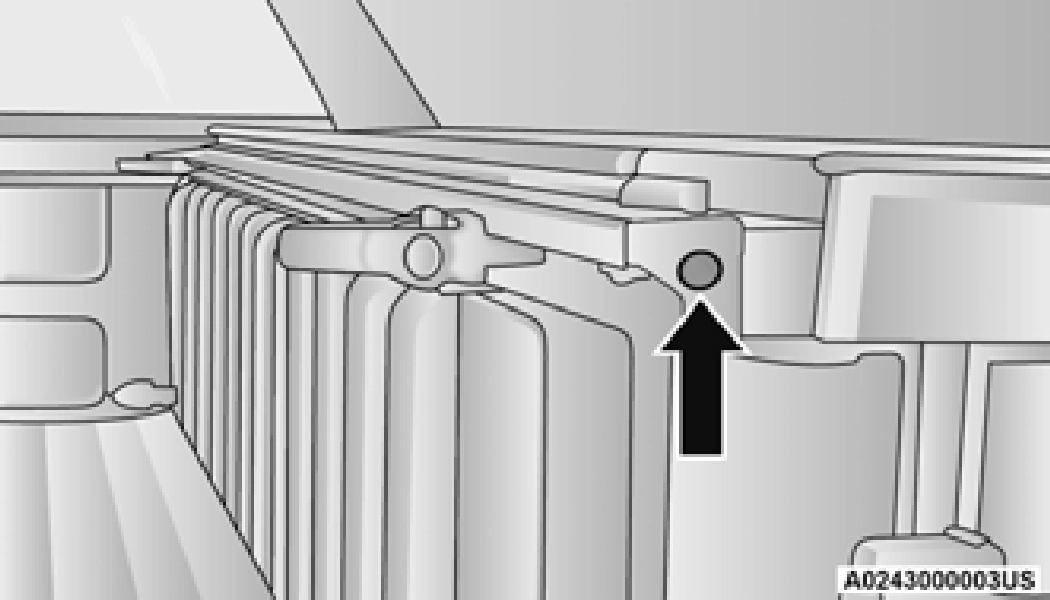
To remove the cleats from the utility rail, remove the end cap screw located in the center of the end cap, using a #T30 Torx head driver.
Remove the end cap and slide the cleat off the end of the rail.
Cleat Removal (Without Tonneau Cover)
Remove the end cap by pushing upward on the release button located beneath the end cap while pulling the cap away from the rail. The cleat can now be removed by sliding it off the end of the rail.
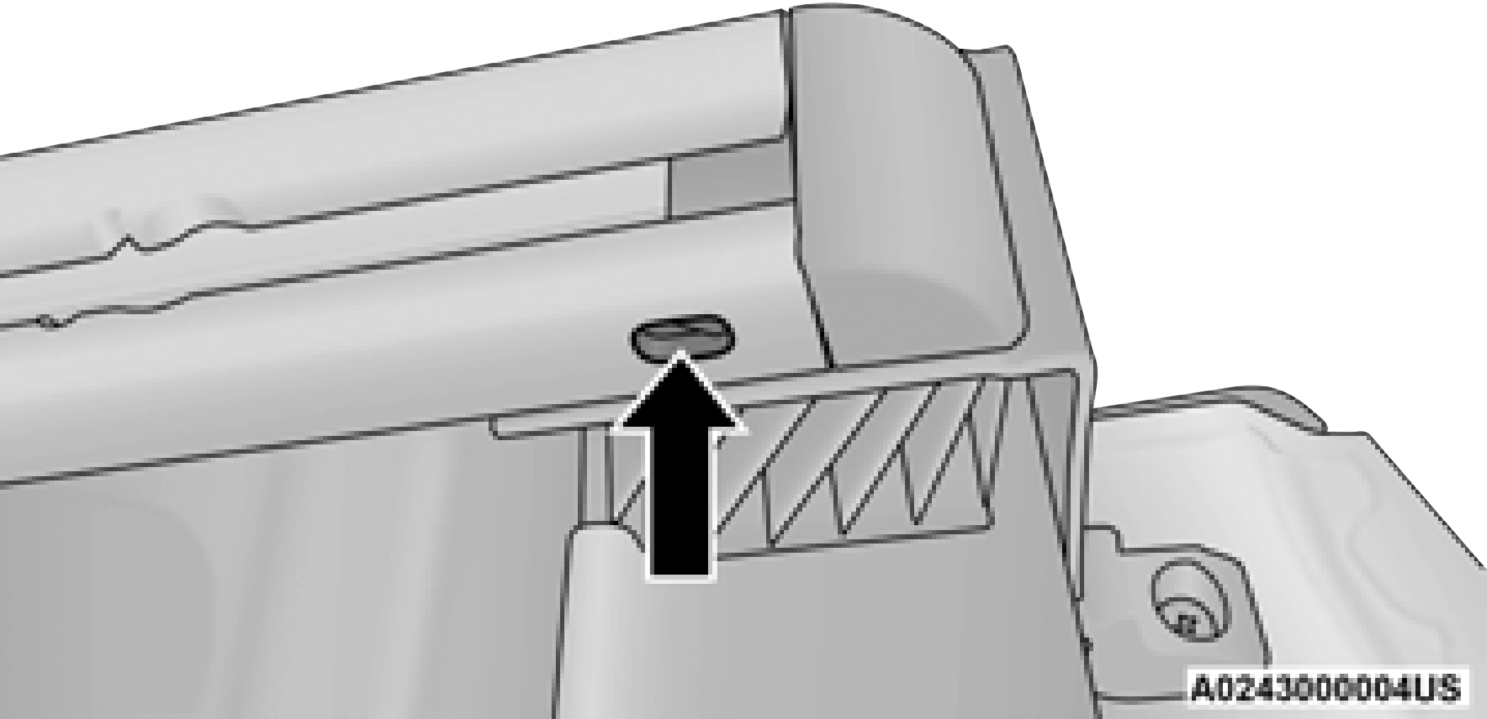
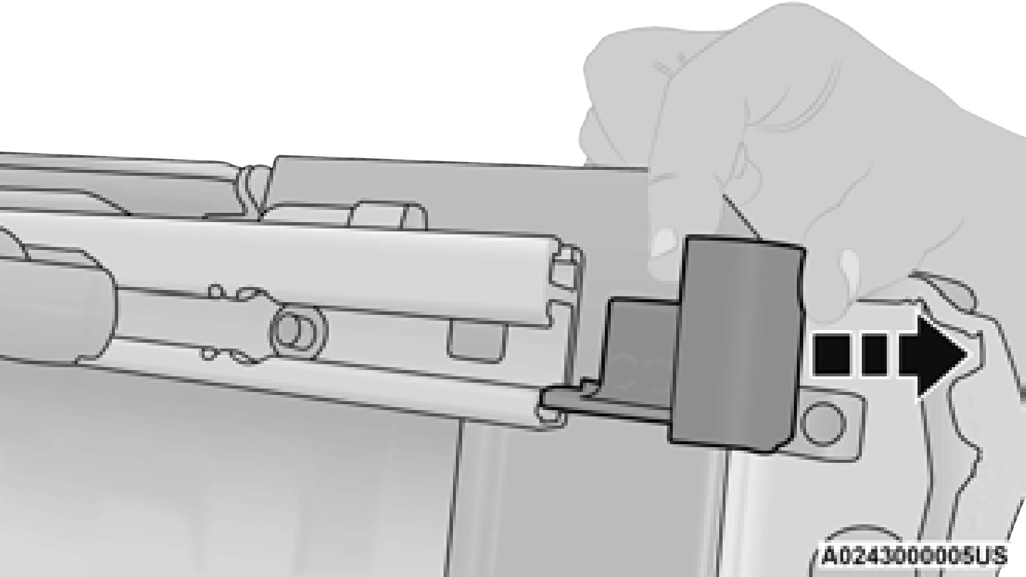
Pull End Cap Away From Rail
Download Manual