JACKING AND TIRE CHANGING
(Continued)
If your vehicle is equipped with an air suspen- sion system, there is a feature which allows the automatic leveling to be disabled to assist with changing a tire.
This feature can be activated through the Uconnect system page 271.
PREPARATIONS FOR JACKING
NOTE:
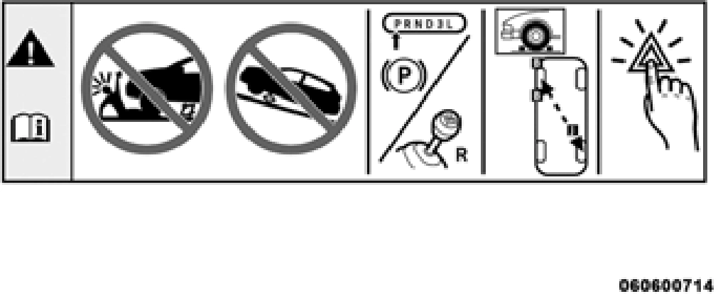
Passengers should not remain in the vehicle when the vehicle is being raised or lifted.
JACK LOCATION
The jack and tools are stored under the front passenger seat.
REMOVAL OF JACK AND TOOLS
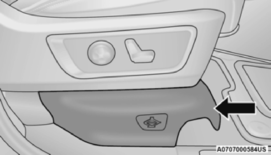
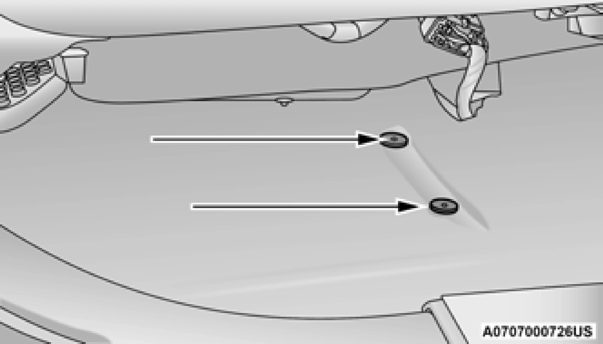
To access the jack and tools, you must remove the plastic access cover located on the side of the front passenger’s seat. To remove the cover, pull the front part of the cover (closest to the front of the seat) toward you to release a locking tab. Once the front of the cover is loose, slide the cover toward the front of the seat until it is free from the seat frame.
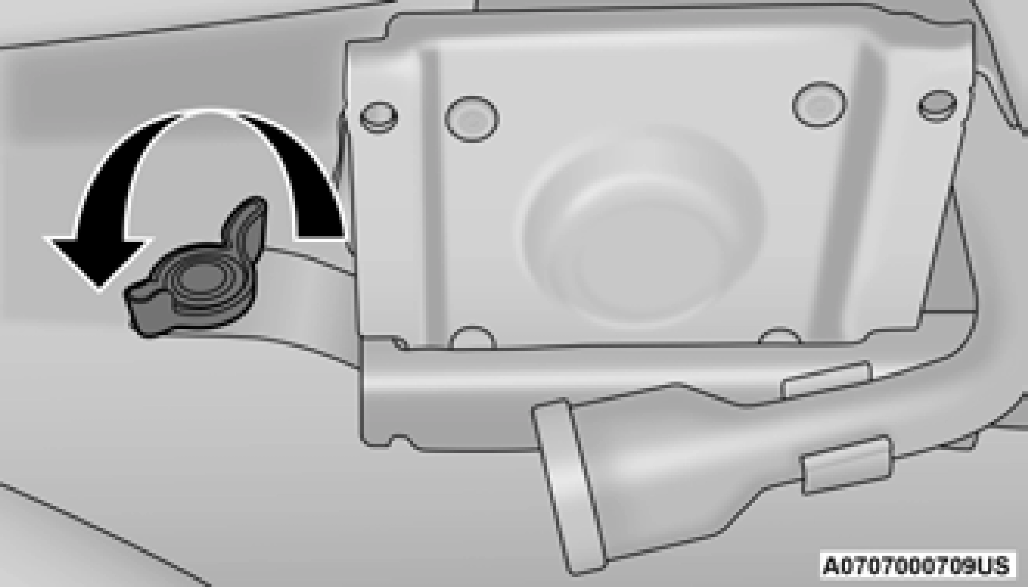
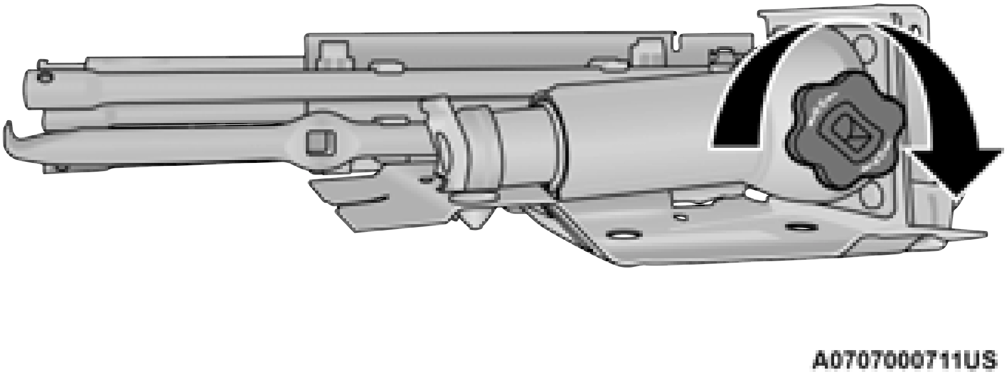
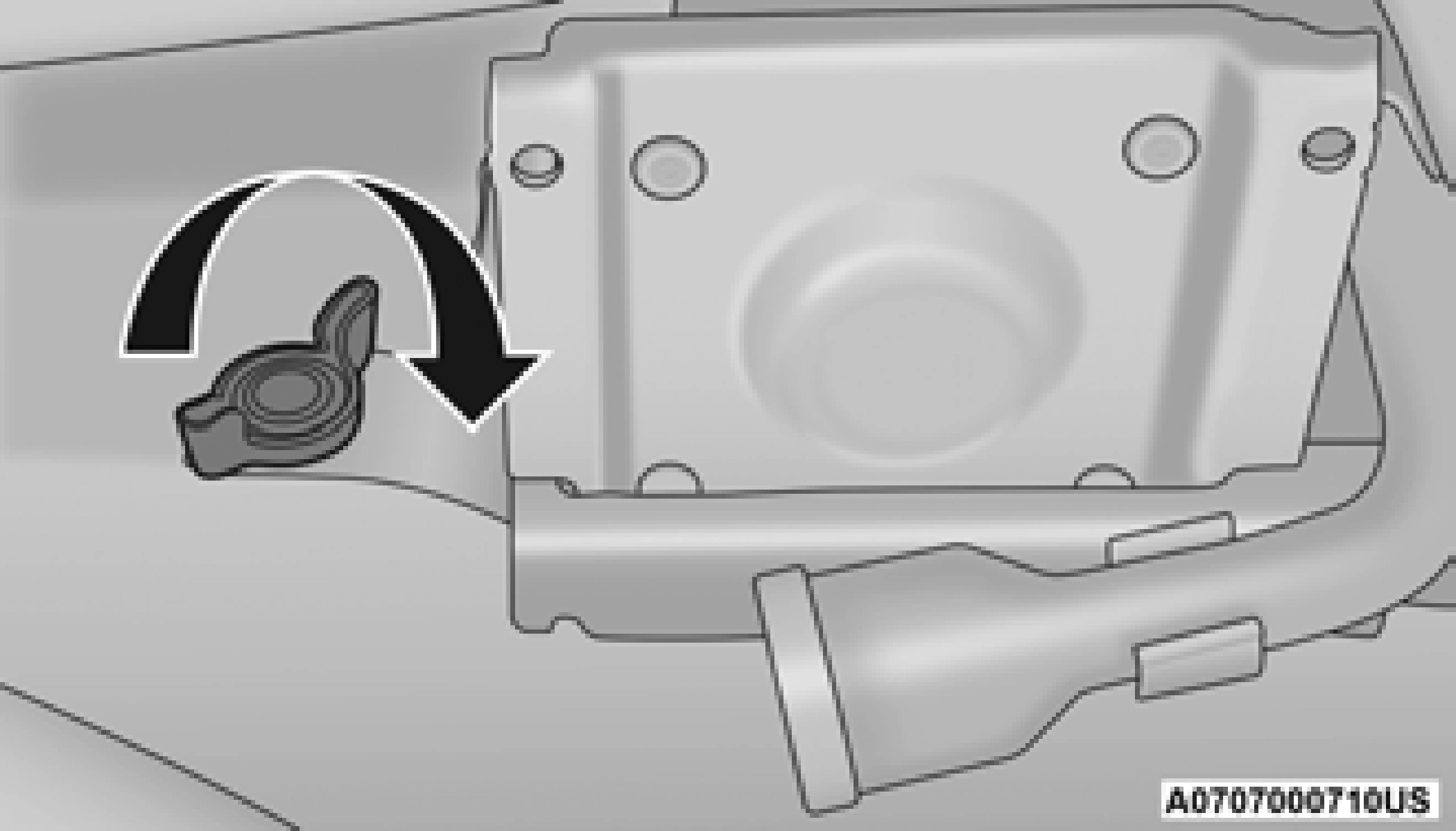
Remove the jack and tools by turning the wing bolt counterclockwise, remove the wing bolt and then slide the assembly out from under the seat.
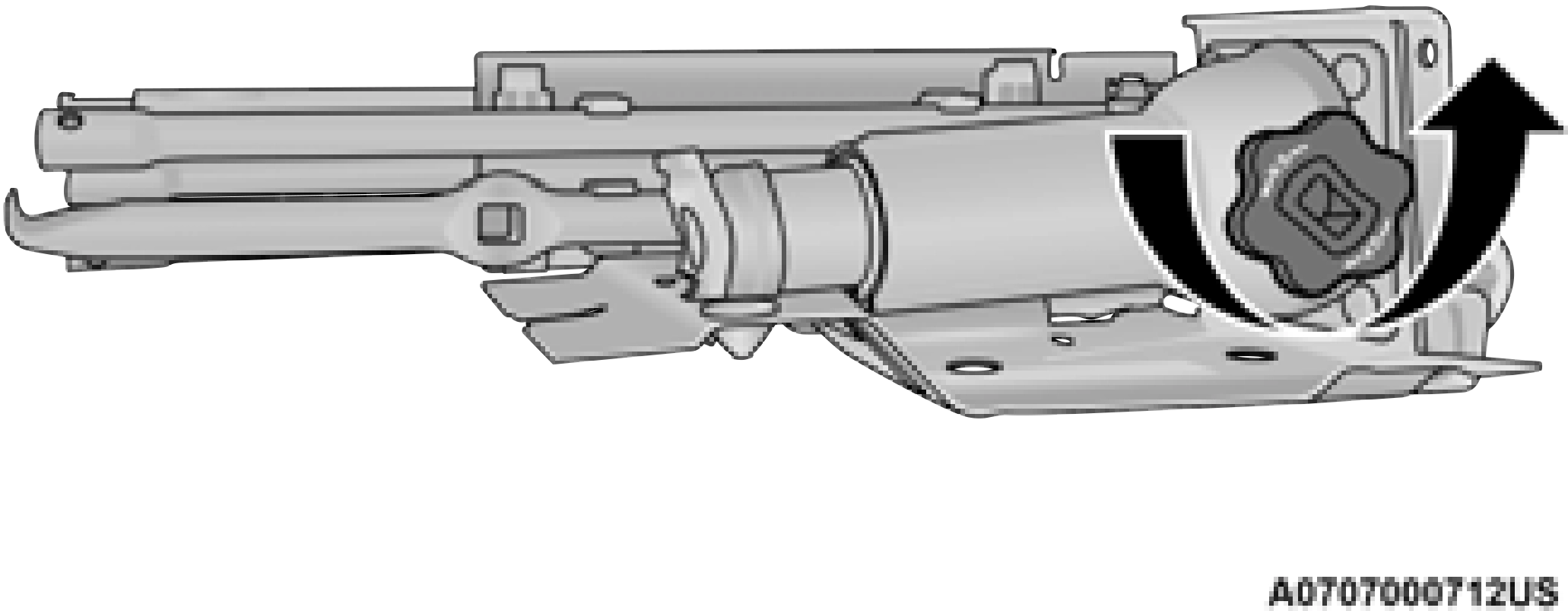
Remove the jack and tools from the bracket assembly. Turn the jack turn-screw counterclockwise to release jack from bracket assembly.
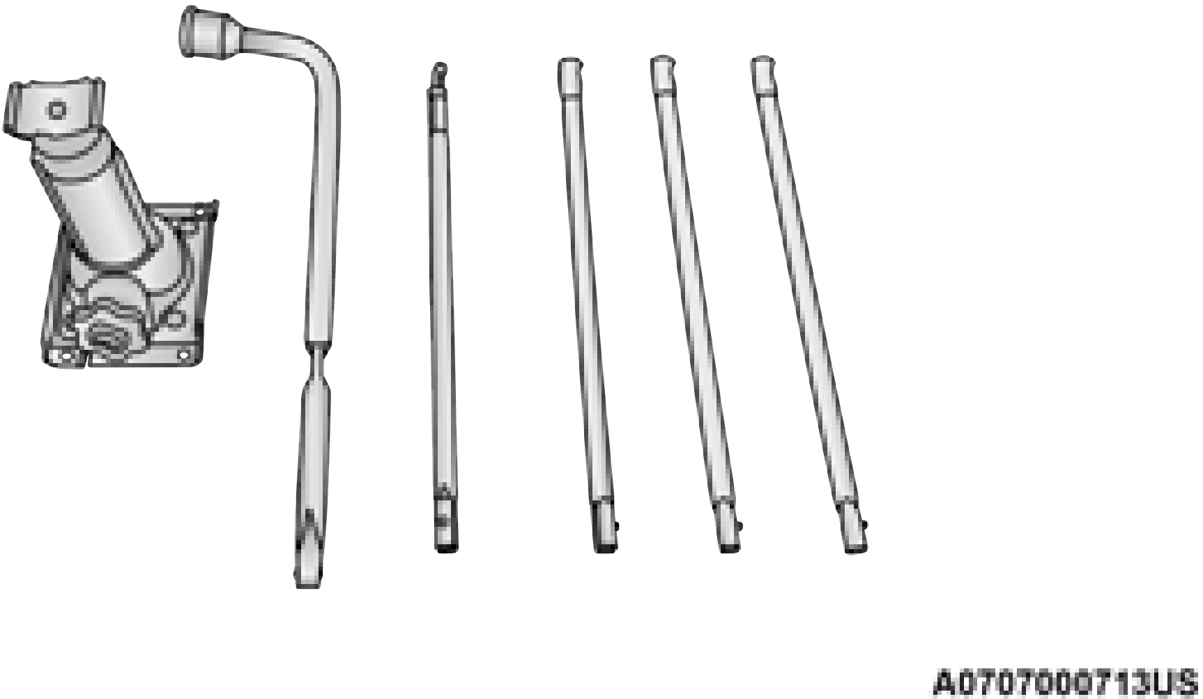
Jacking Tools
There are two ways to assemble the tools: Assembled For Spare Tire Lowering/Raising
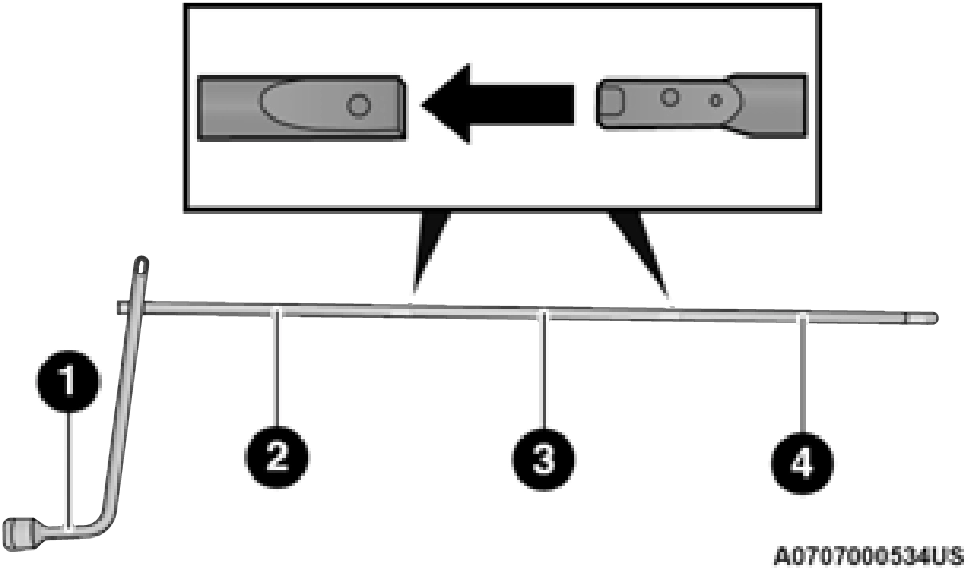
1 — Lug Wrench 2 — Extension 2
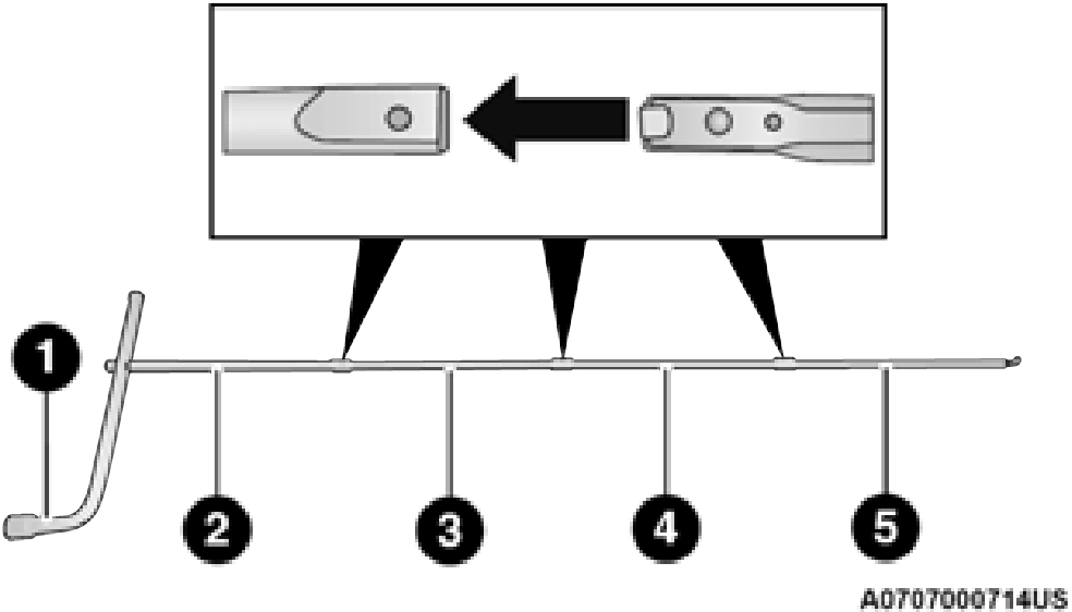
Assembled For Jack Operation
1 — Lug Wrench 2 — Extension 2
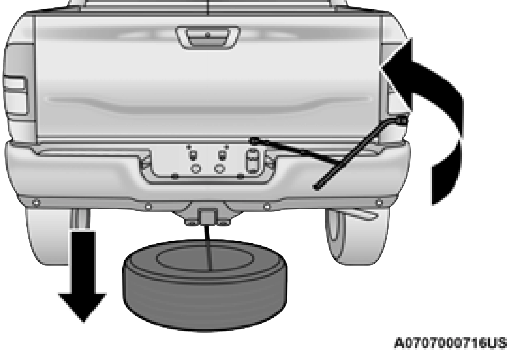
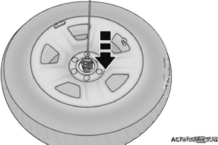
2. Rotate the lug wrench handle counter- clockwise until the spare tire is on the ground with enough cable slack to allow you to pull it out from under the vehicle.
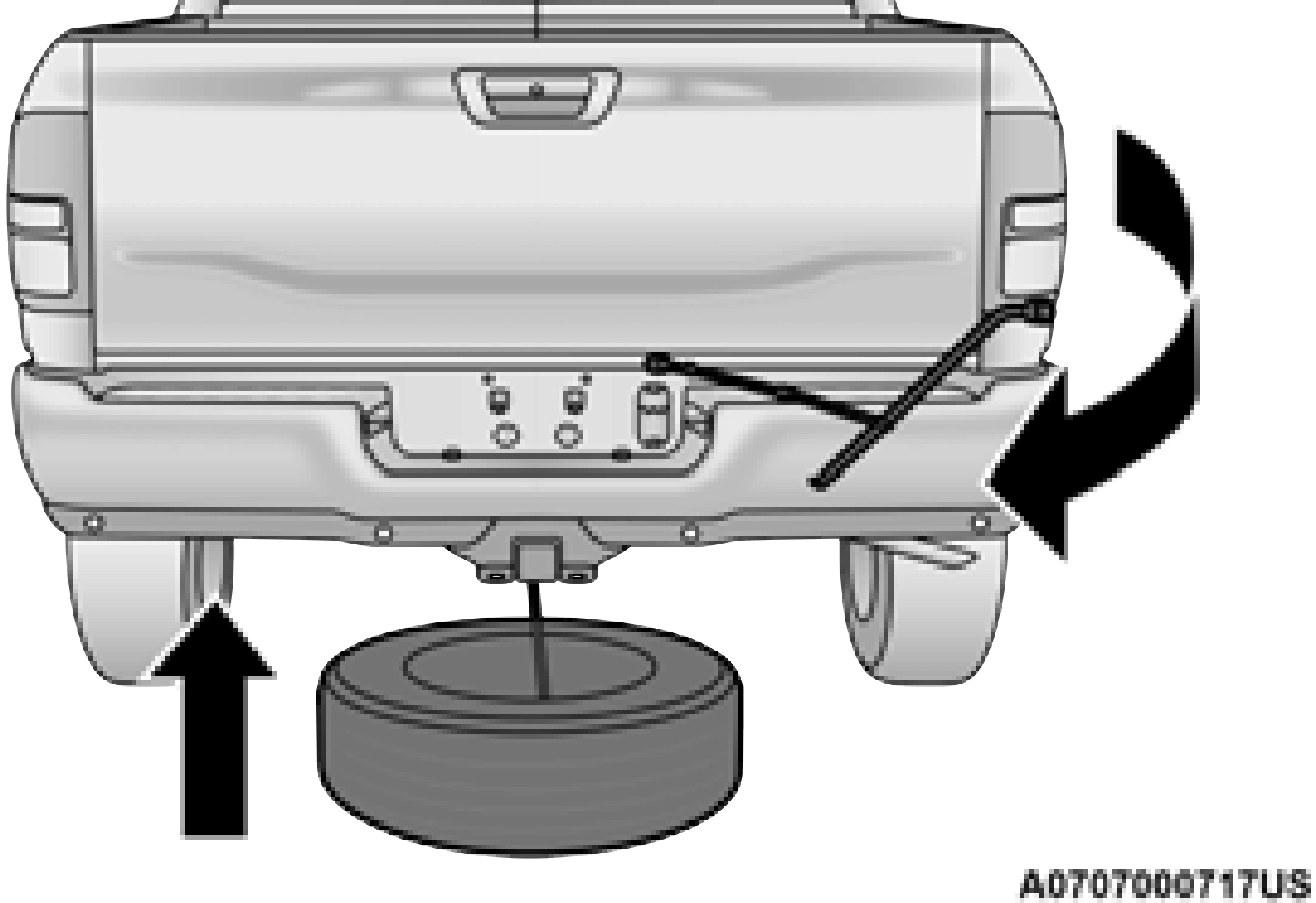
REMOVING THE SPARE TIRE
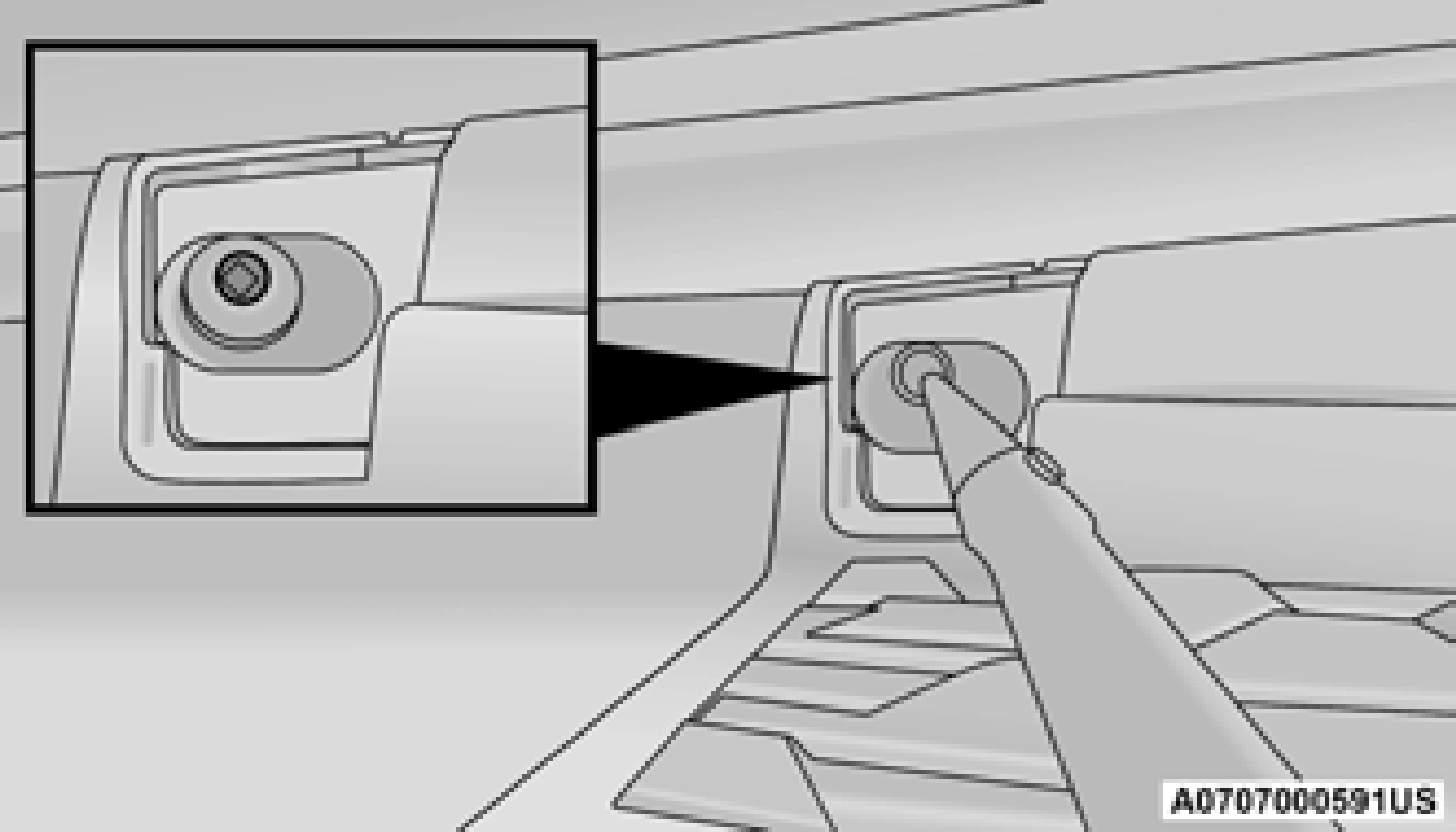
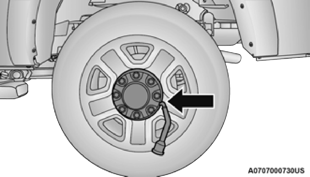
1. Remove the spare tire before attempting to jack up the truck. Attach the lug wrench to the extension tubes with the curved angle facing away from the vehicle. Insert the extension tube through the access hole between the lower tailgate and the top of the fascia/bumper and into the winch mechanism tube.
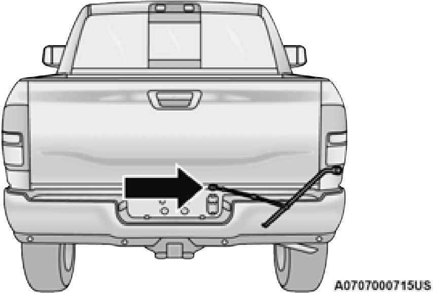
Inserting The Extension Tubes Into The Access Hole
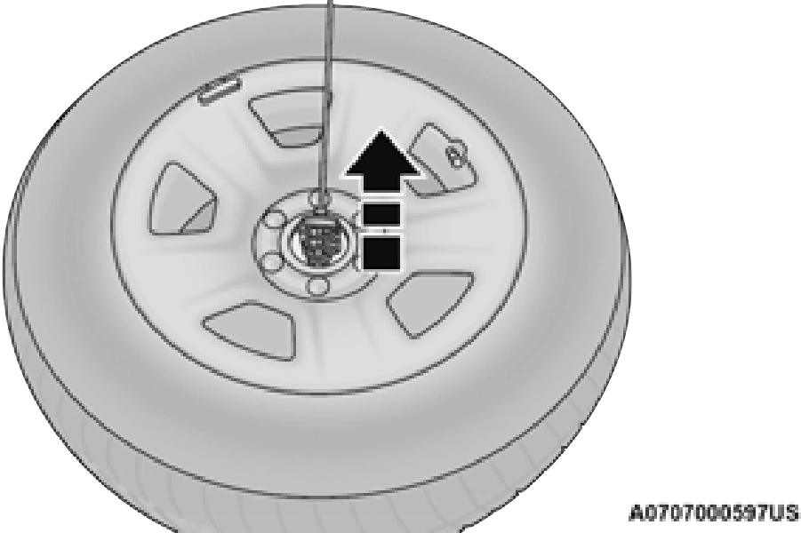
Pulling The Spare Tire Out
The winch mechanism is designed for use with the extension tubes only. Use of an air wrench or other power tools is not recommended and can damage the winch.
JACKING INSTRUCTIONS
If your vehicle is equipped with hub caps/wheel covers they must be removed before raising the vehicle off the ground page 383.
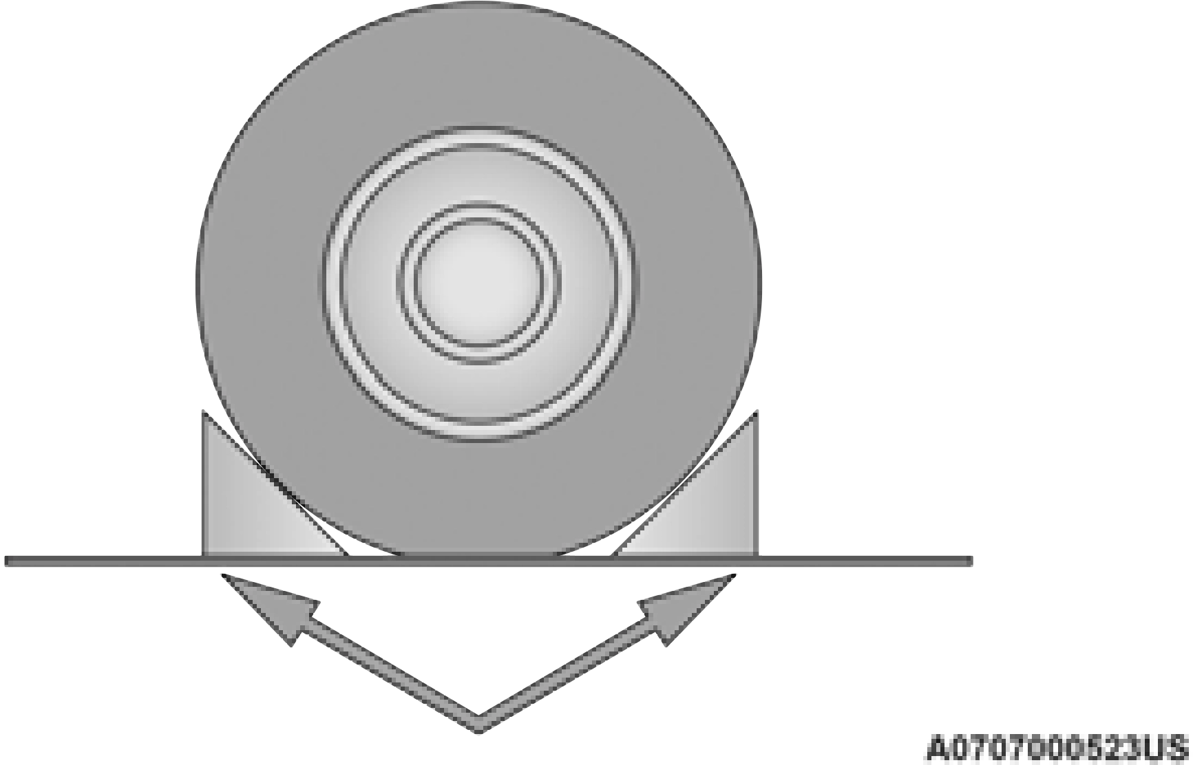
3. Placement of the jack is critical:
Lug Wrench Adapter And Wrench
Jack / Extensions Placement
Front Jacking Location
When changing the front wheel, assemble the jack driver to the jack and connect the
jack driver to the extension tubes. Place the 7
jack under the axle as close to the tire as pos- sible with the drive tubes extending to the front. Connect the extension tubes and lug wrench.
Front Jacking Location
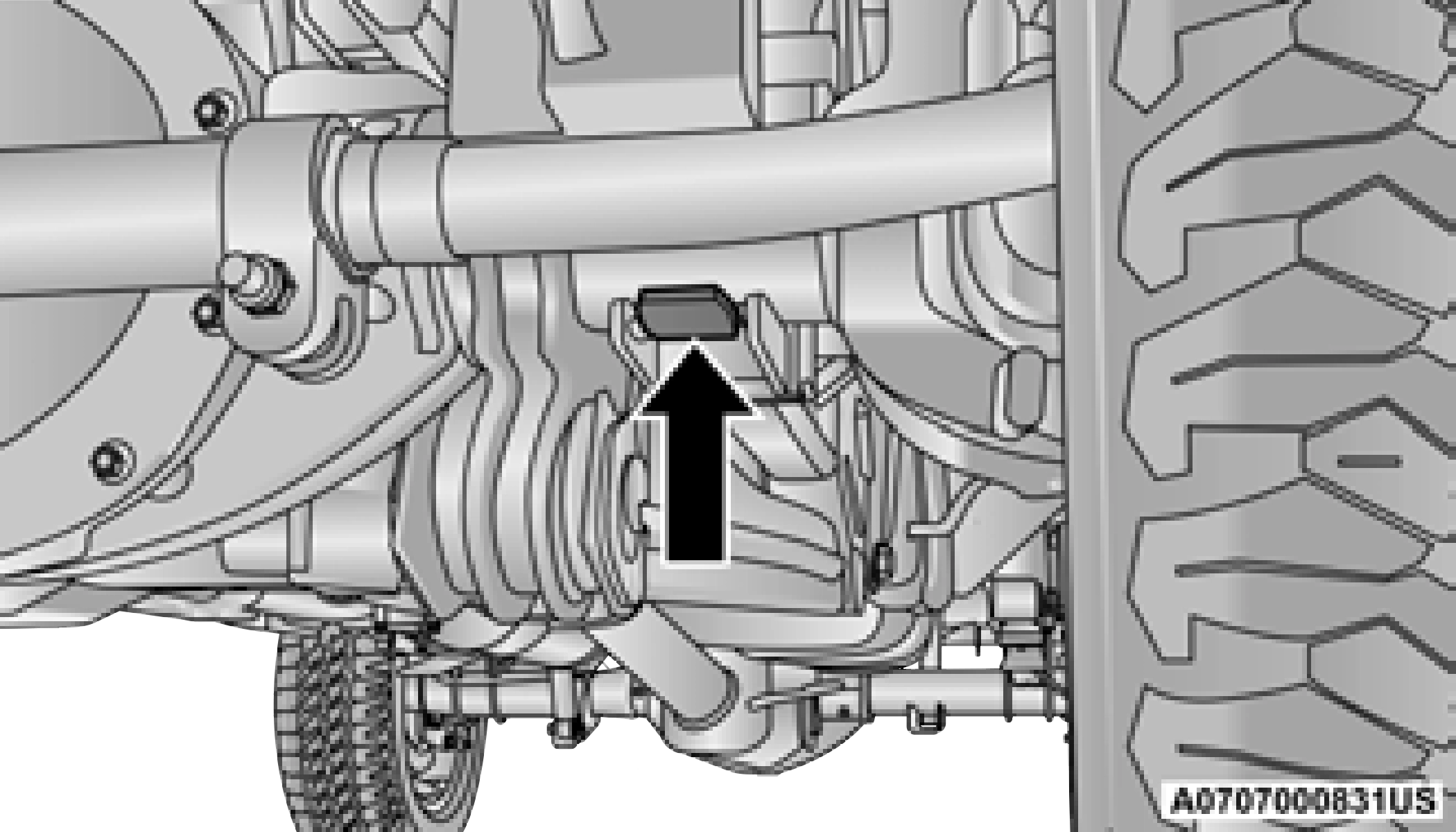
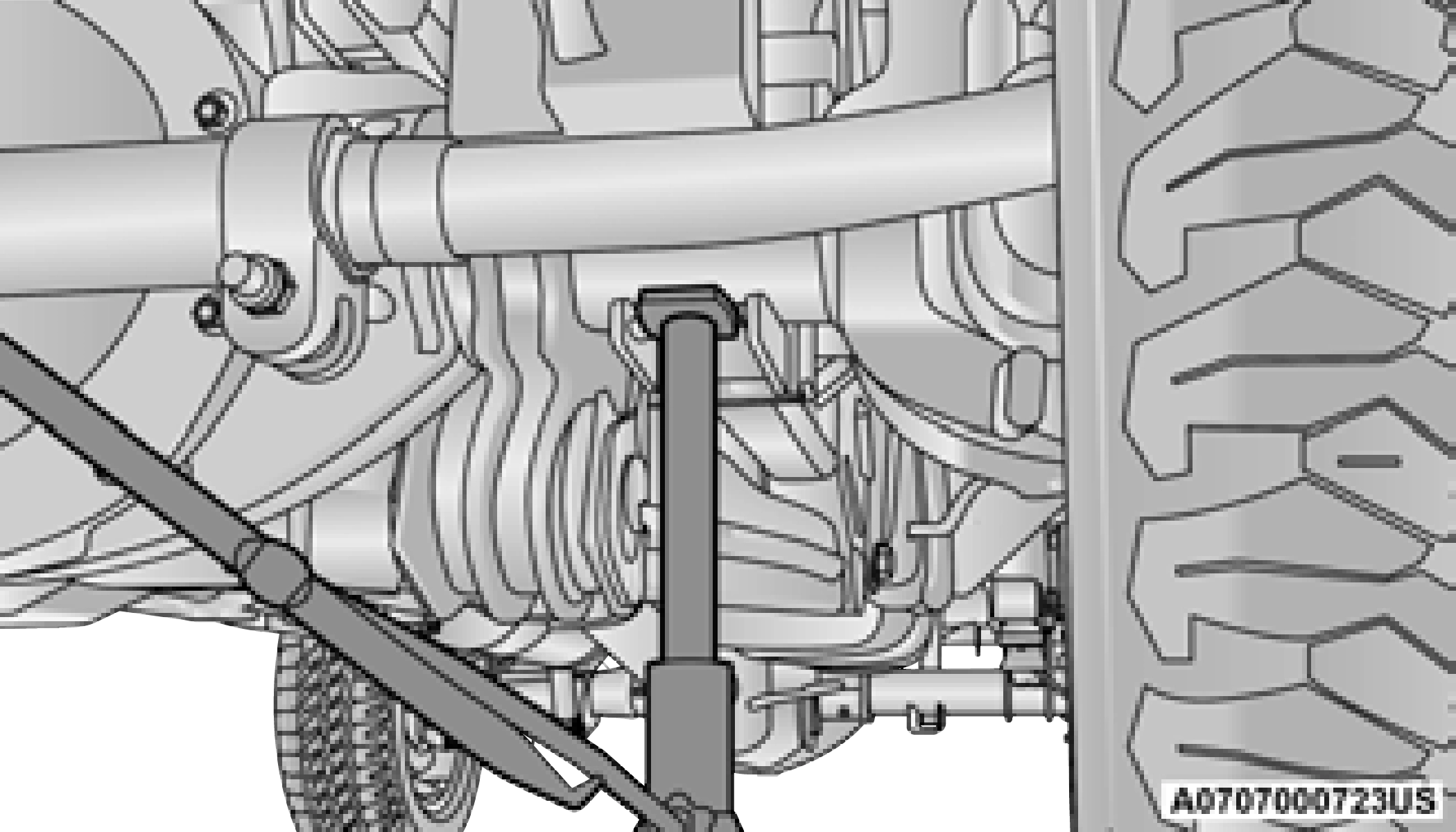
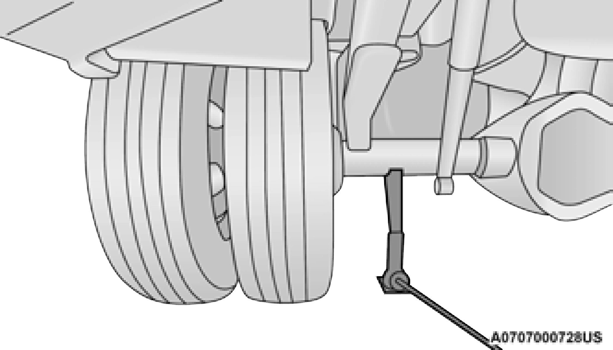
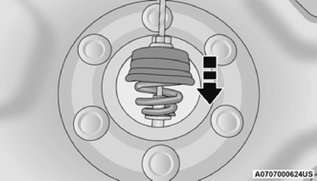
Rear Jacking Location
When changing a rear wheel, assemble the jack driver to the jack and connect the jack driver to the extension tubes. Place the jack
under the axle between the spring and the shock absorber with the extension tubes ex- tending to the rear.
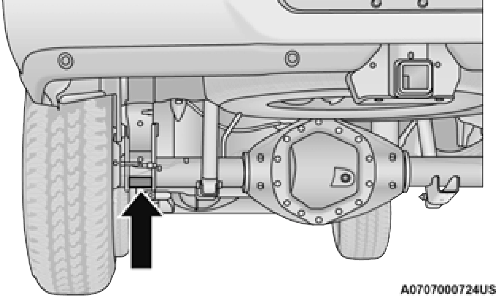
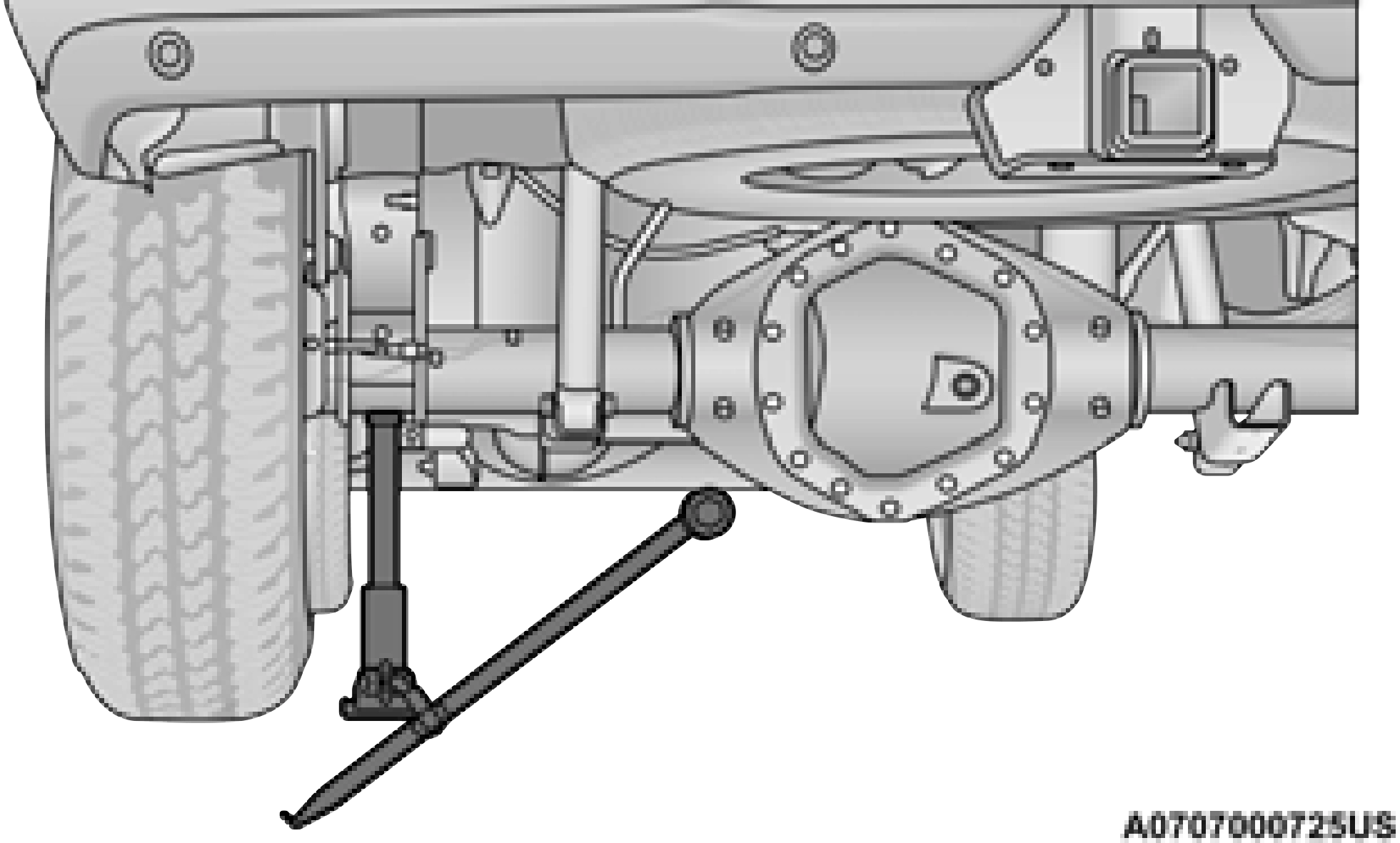
Rear Jacking Location
Connect the extension tubes and lug wrench.
If the bottle jack will not lower by turning the dial (thumbwheel) by hand, it may be necessary to use the jack driver in order to lower the jack.
Dual Rear Wheel Jack Placement
The bottle jack will not lower by turning the dial (thumbwheel) by hand, it may be necessary to use the jack driver in order to lower the jack.
Do not oil wheel studs. For chrome wheels, do
not substitute with chrome plated lug nuts. 7
TO STOW THE FLAT OR SPARE
Have the flat tire repaired or replaced immedi- ately.
The winch mechanism is designed for use with the jack extension tube only. Use of an air wrench or other power tools is not recom- mended and can damage the winch.
REINSTALLING THE JACK AND TOOLS
NOTE:
Ensure that the jack and tool bracket assembly slides into the front hold down location.
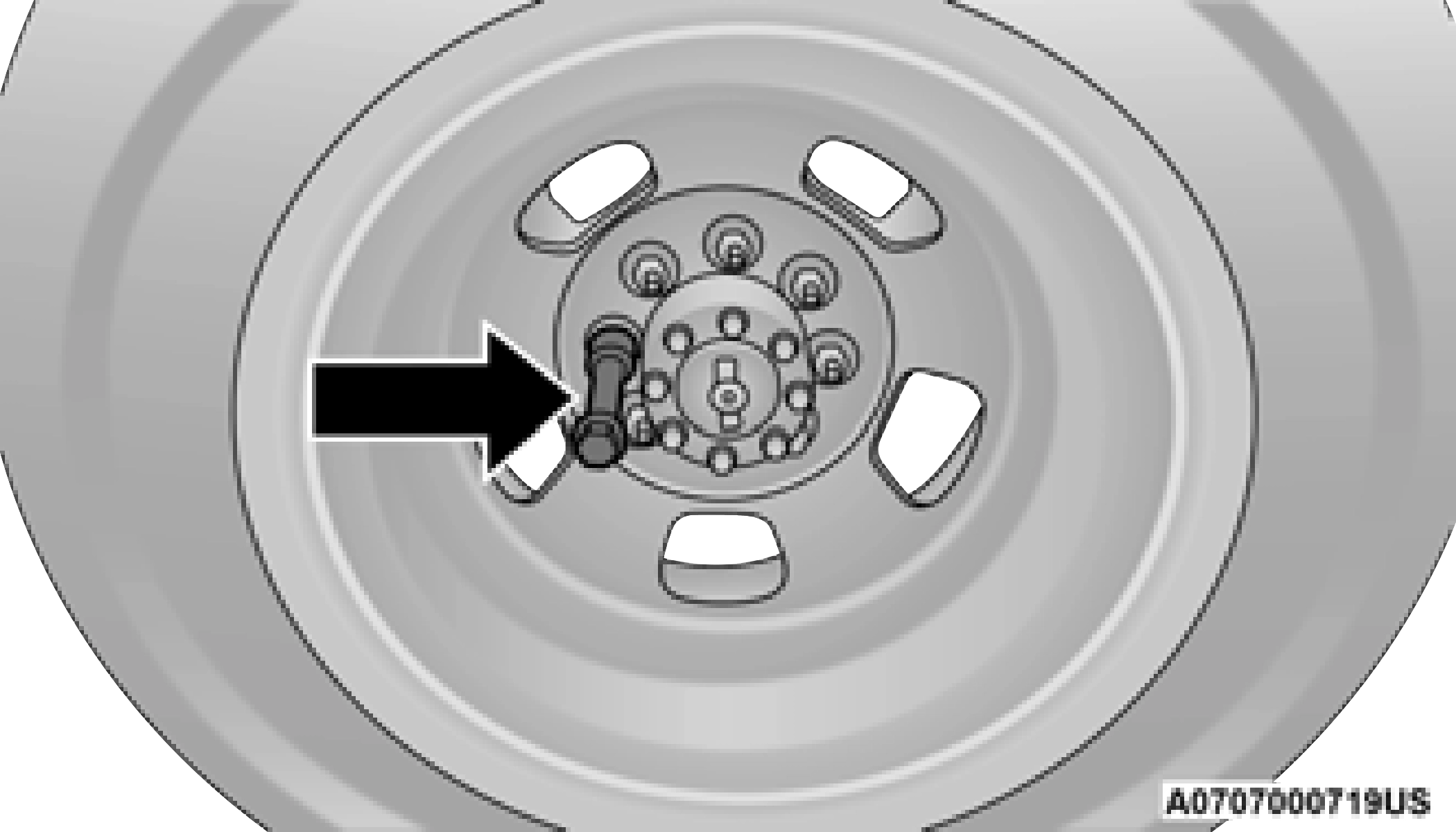
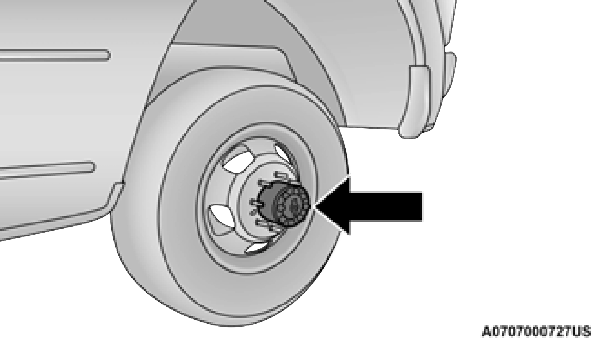
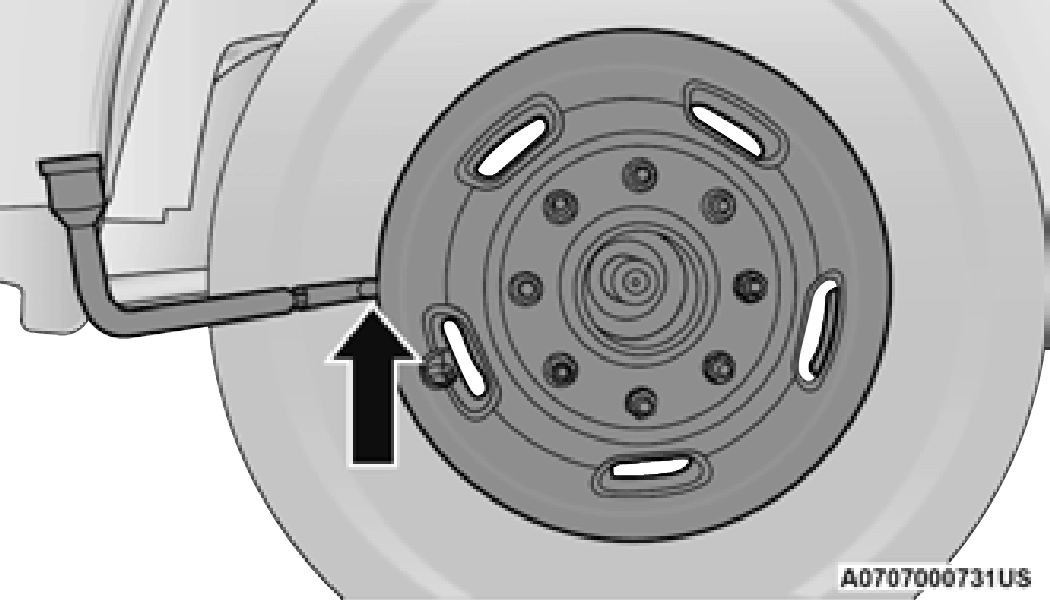
HUB CAPS/WHEEL COVERS — IF EQUIPPED
The hub caps must be removed before raising the vehicle off the ground.
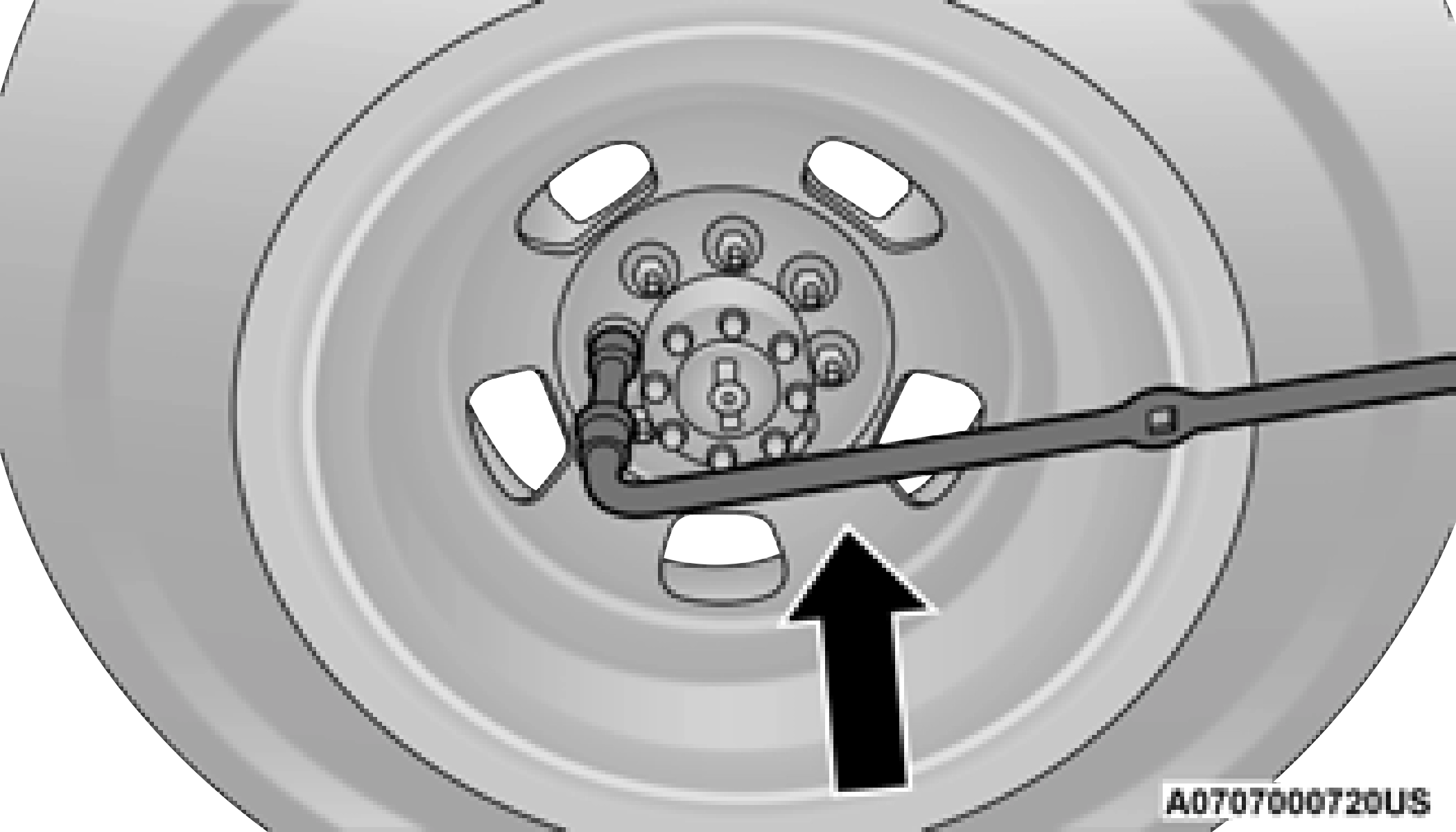
For 2500/3500 Single Rear Wheel (SRW) models, use the flat end of the lug wrench to hook and pull off the hub cap. Find the opening in the hub cap, insert the lug wrench, and pull off the cap. If you need to pry against the wheel, protect the wheel surface.
On 3500 models with Dual Rear Wheels (DRW), you must first remove the hub caps—use the procedure noted for the single rear wheel. For the wheel covers (wheel skins), insert the flat end of the lug wrench between the outer edge of the wheel cover and the wheel. Pry against the wheel to remove the wheel cover. Repeat this procedure around the wheel until the cover pops off.
Replace the wheel covers using a rubber mallet to ease the installation. Align the wheel cover vent holes to the wheel vent holes. Tap on the wheel cover as needed to firmly seat it evenly around the wheel.
Download Manual