Jacking and tire changing
WARNING:
-
Do not attempt to change a tire on the side of the vehicle close to moving traffic. Pull far enough off the road to avoid the danger of being hit when operating the jack or changing the wheel.
-
Being under a jacked-up vehicle is dangerous. The vehicle could slip off the jack and fall on you. You could be crushed. Never put any part of your body under a vehicle that is on a jack. If you need to get under a raised vehicle, take it to a service center where it can be raised on a lift.
-
Never start or run the engine while the vehicle is on a jack.
-
The jack is designed to be used as a tool for changing tires only. The jack should not be used to lift the vehicle for service purposes. The vehicle should be jacked on a firm level surface only. Avoid ice or slippery areas.
JACK LOCATION
If equipped, the jack, jack handle and winch handle tools are stowed behind the rear left side trim panel in the rear cargo area. Turn the two cover latches to release the cover.
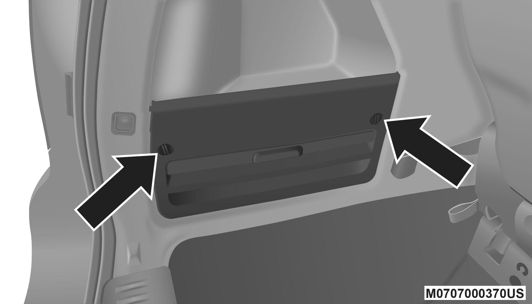
Jack And Tool Cover
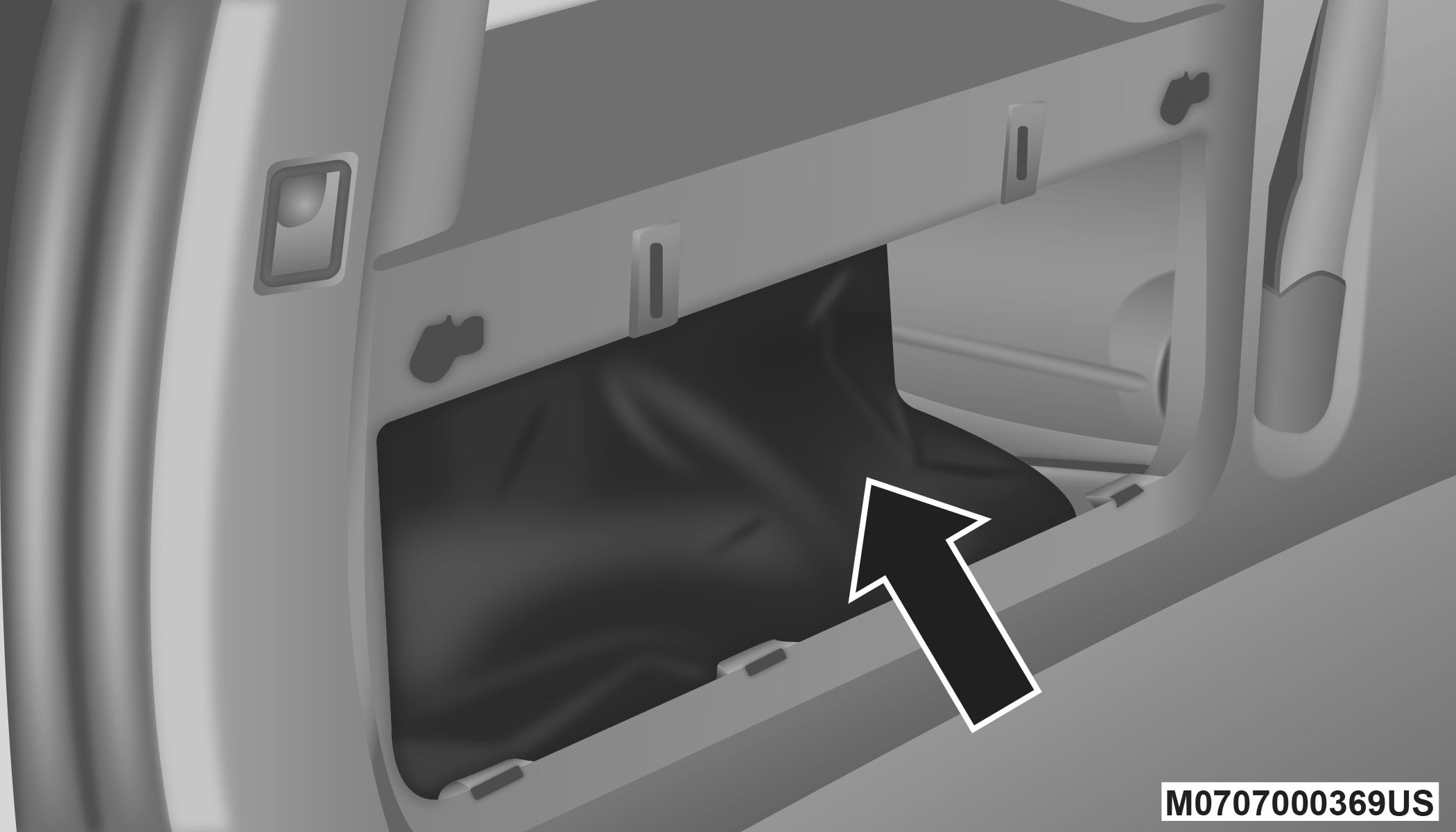
Jack And Tool Location
SPARE TIRE TOOLS
The tool pouch contains three pieces and can be assembled into a spare tire hook; to remove the compact spare tire/cover assembly from under the vehicle, or a Winch T-handle; to raise/lower the compact spare tire/cover assembly.
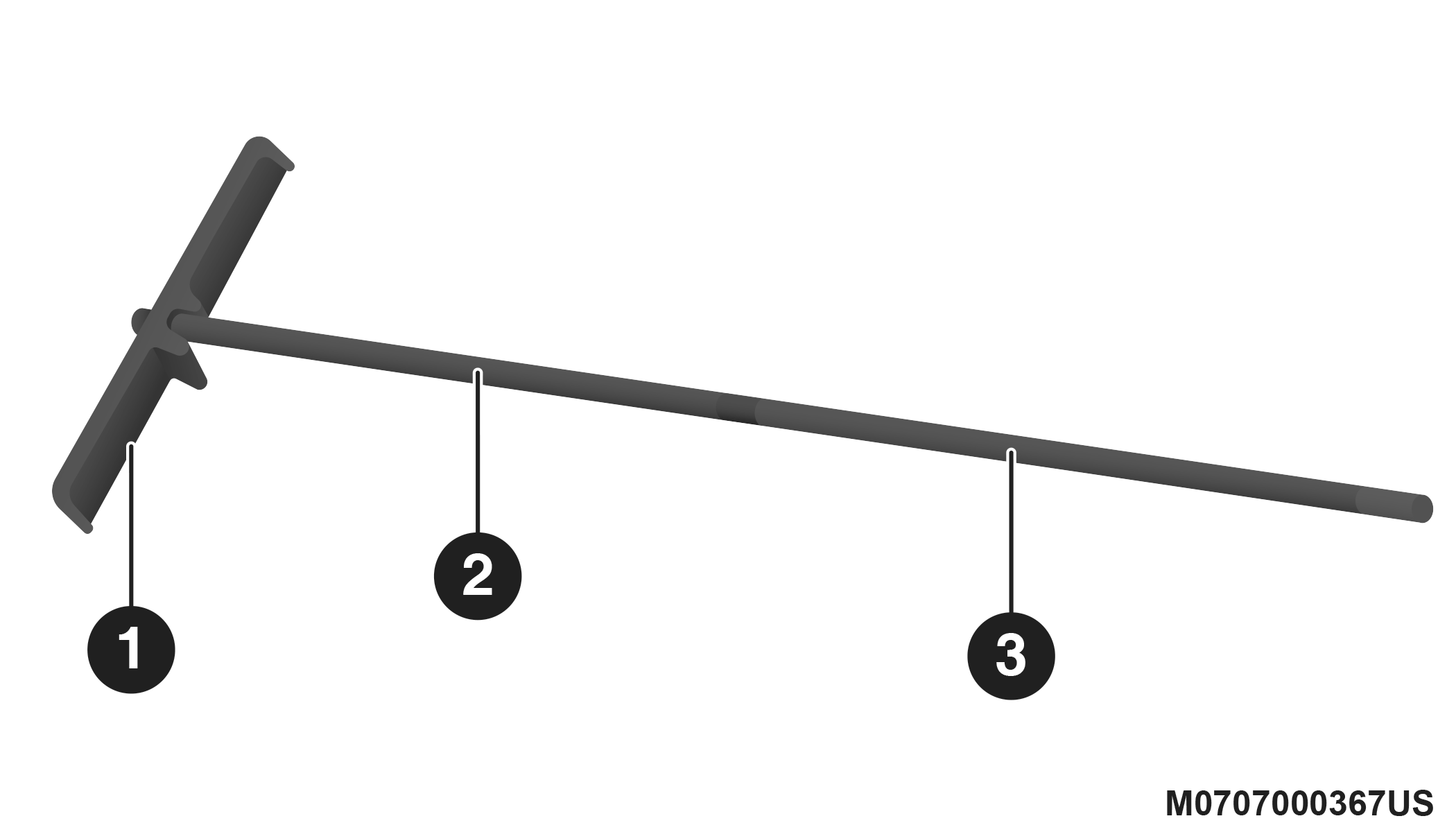
Assembled T-handle
|
1 — Spare Tire Hook/T-handle |
|
2 — Extension 1 |
|
3 — Extension 2 |
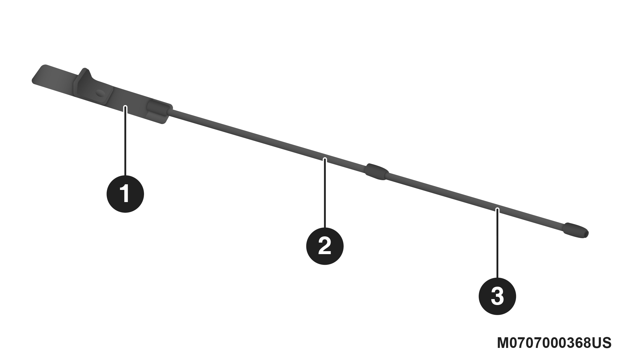
Assembling The Spare Tire Hook
|
1 — Spare Tire Hook/T-handle |
|
2 — Extension 1 |
|
3 — Extension 2 |
TO ACCESS SPARE TIRE WINCH DRIVE NUT
To access the spare tire winch drive nut and lower the spare tire, you will need to refer to one of the following center console configurations.
SUPER CONSOLE — IF EQUIPPED
For vehicles equipped with the Super Console, the spare tire winch assembly drive nut is located beneath the console.
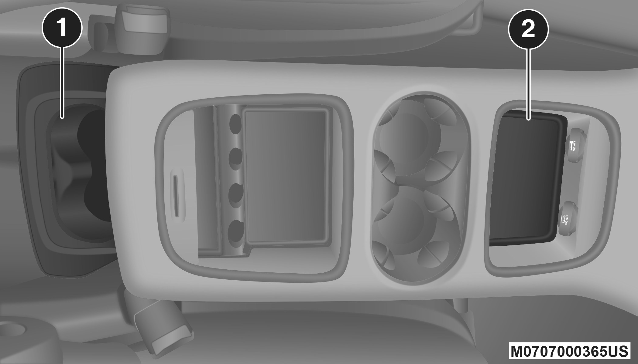
Super Console
|
1 — Lower Drawer |
|
2 — Front Drawer/Liner |
-
Pull the lower drawer out from the rear of the floor console to gain clear access to the tire winch drive nut.
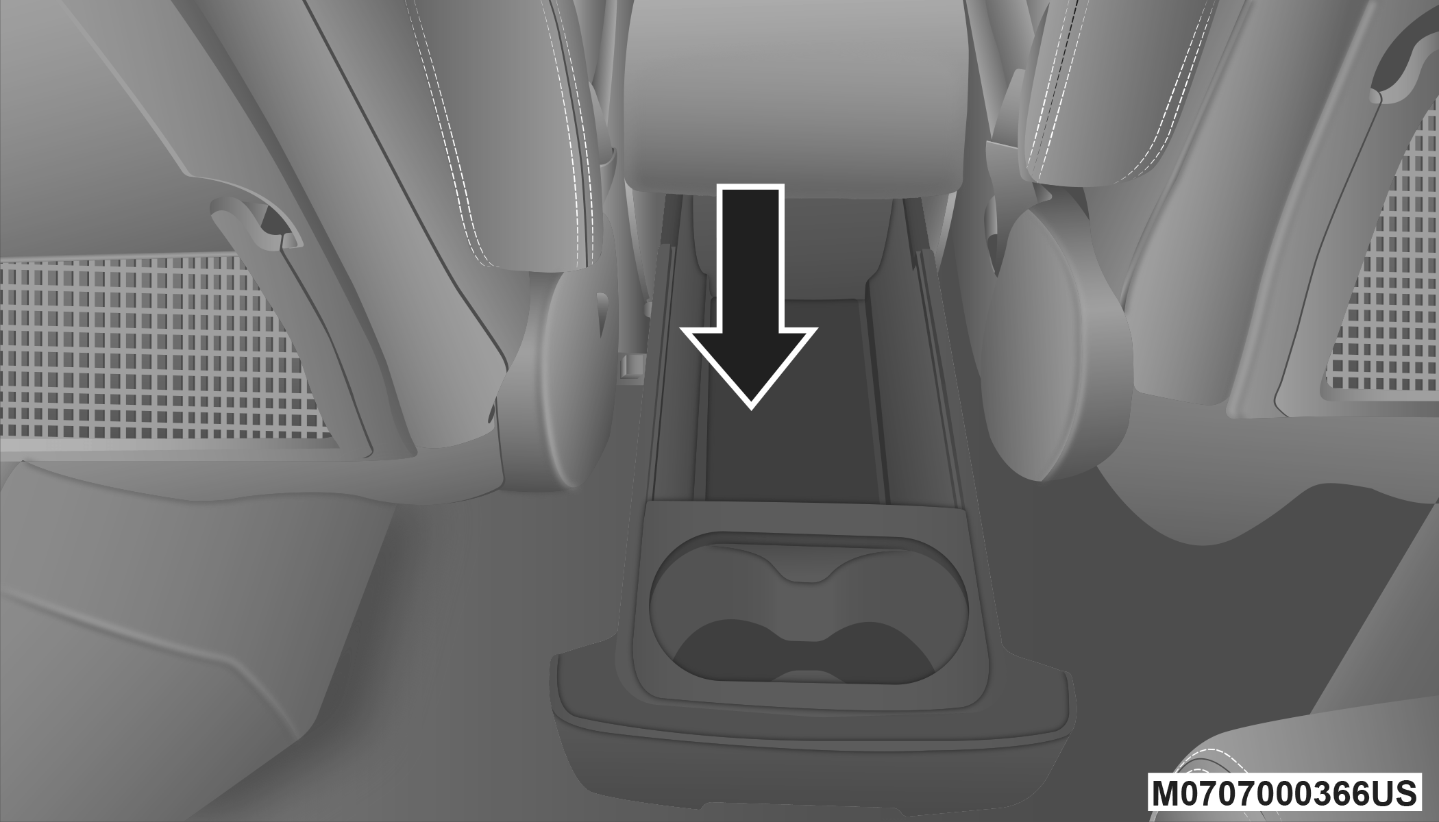
Lower Storage Compartment Location
-
Open the front drawer to expose the storage compartment.
-
Remove the liner from the consoles storage compartment to access the spare tire winch drive nut.
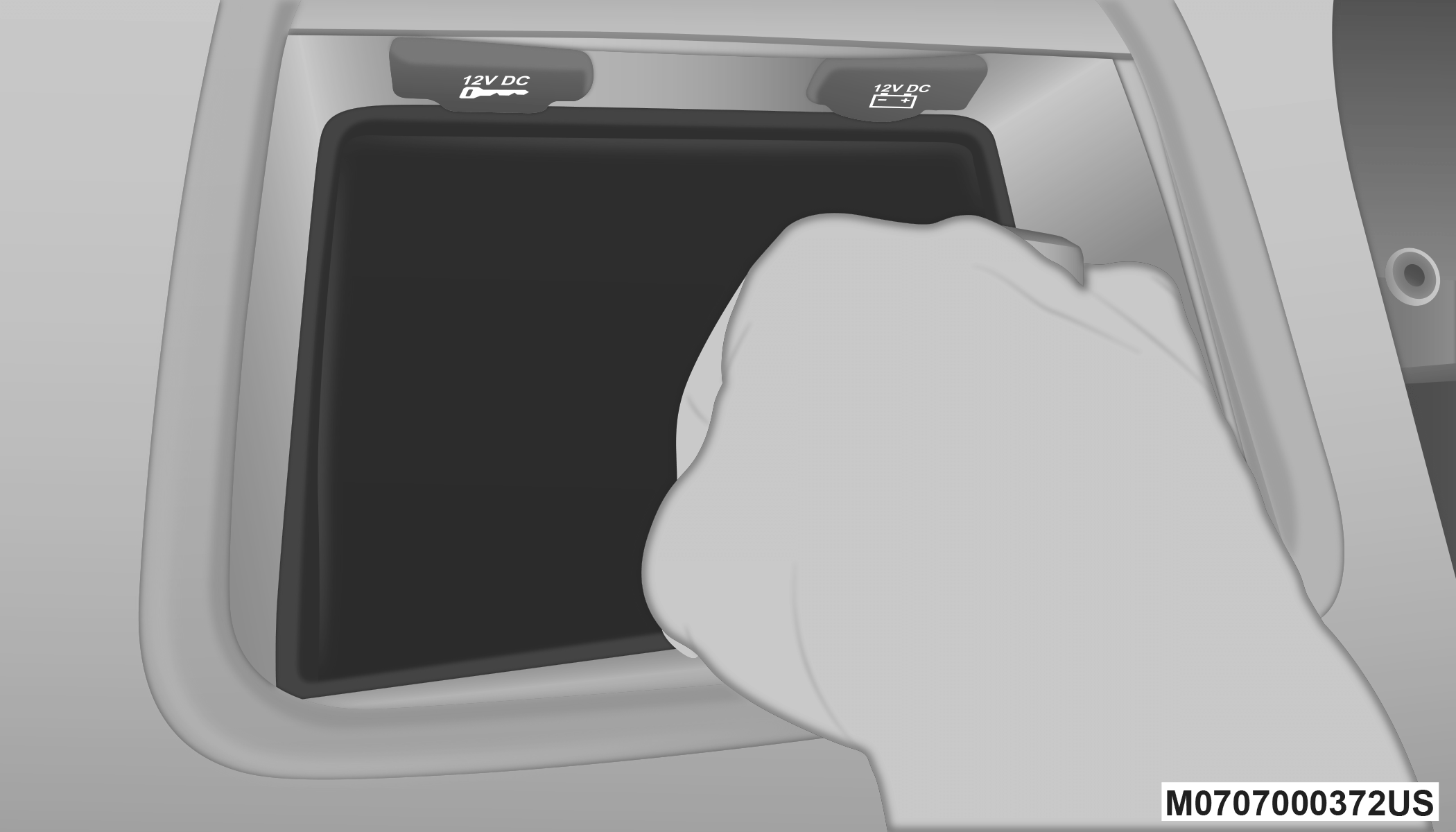
Removing Liner
Winch Drive Nut Location
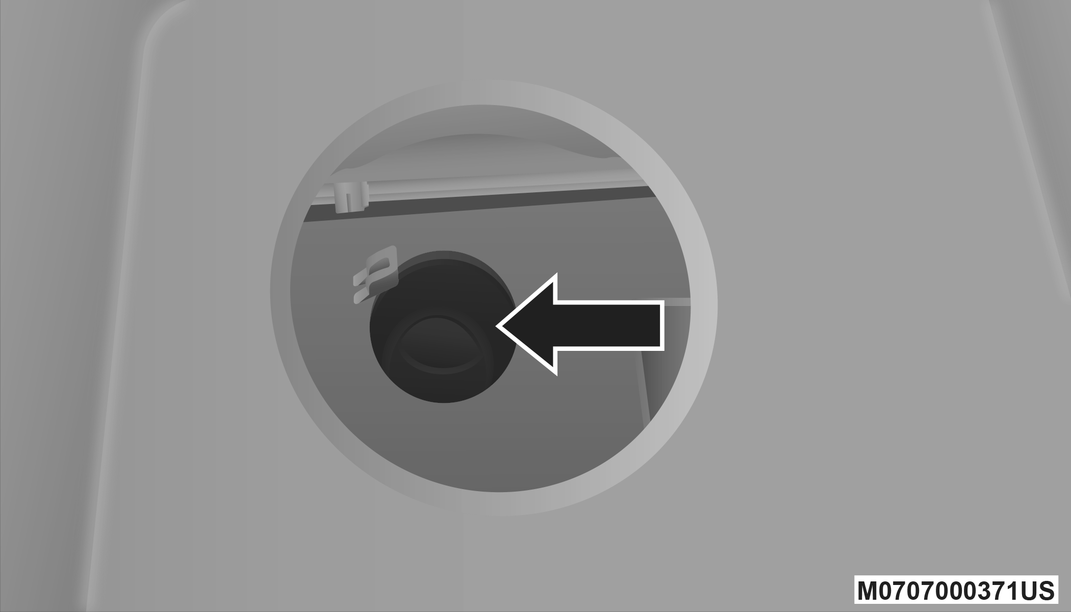
BASE CARGO CENTER CONSOLE — IF EQUIPPED
Pull the Winch Cover assembly plug and retainer clip to access the winch drive nut.
Winch Cover Assembly Plug (If Equipped)
SPARE TIRE REMOVAL
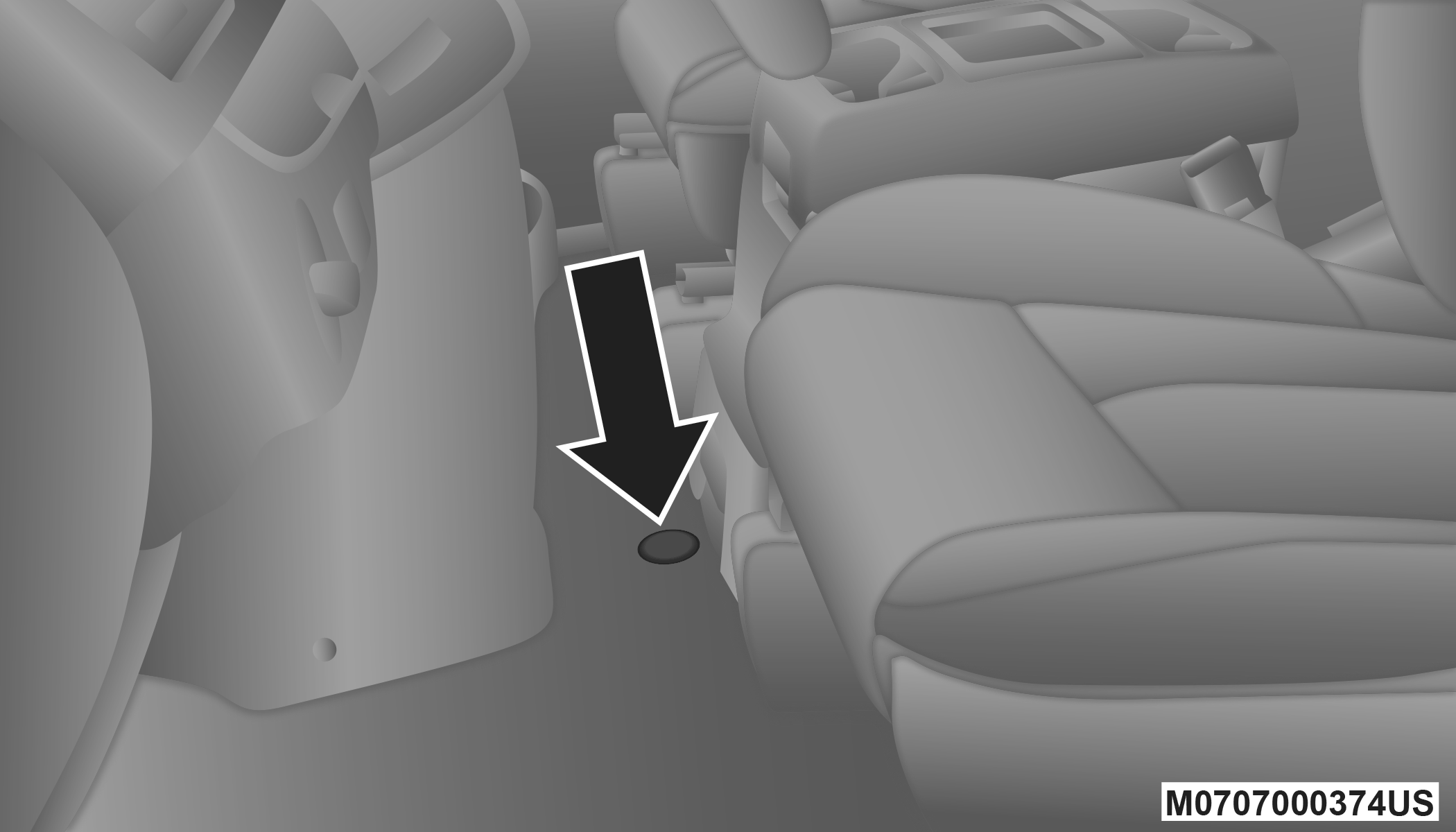
The spare tire is stowed inside a protective cover located under the center of the vehicle between the front doors by means of a cable winch mechanism. The “spare tire drive” nut is located on the floor, under a plastic cap at the front of the floor console or under front super console forward bin liner.
Spare Tire Location
SPARE TIRE REMOVAL INSTRUCTIONS
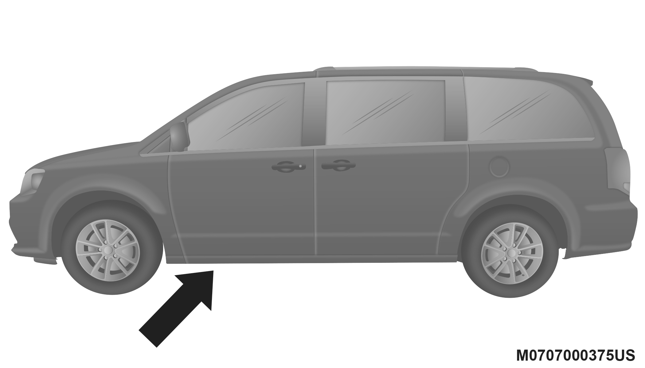
The spare tire is located under the vehicle beneath the center console area.
Spare Tire And Cover
-
Assemble the spare tire tools into a T-handle and place the square end over the spare tire winch drive nut.
-
Rotate the nut to the left until the winch mechanism stops turning freely. This will allow enough slack in the cable to allow you to pull the spare tire out from underneath the vehicle.
CAUTION:
The winch mechanism is designed for use with the winch T-handle only. Use of an air wrench or other power tools is not recommended and can damage the winch.
-
To remove the compact spare tire/cover assembly, assemble the winch T-handle extensions to form a spare tire hook, and pull the spare tire out from under the vehicle.
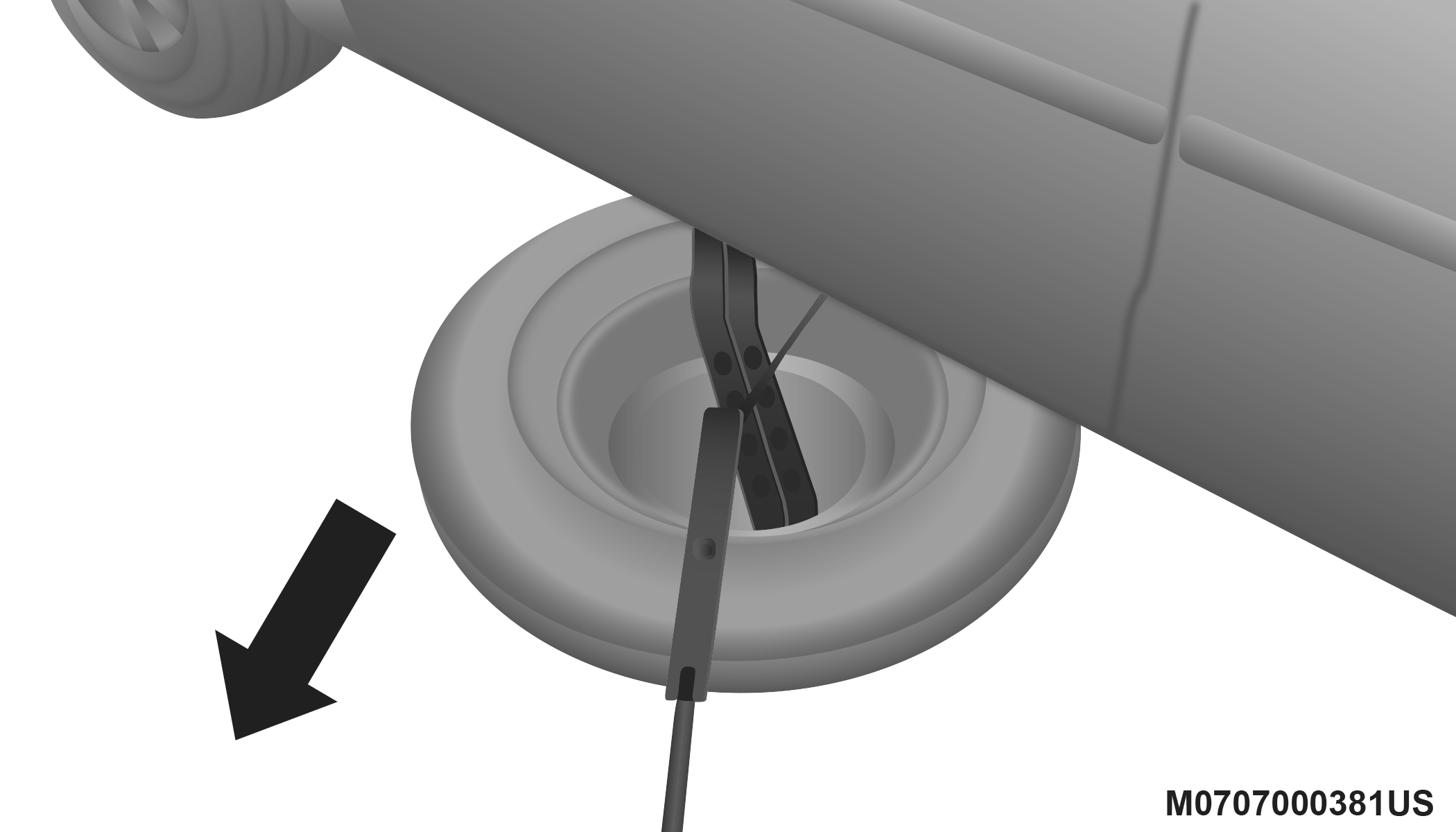
Pulling Spare Tire
Note:
If either front tire is flat it may be necessary to jack up the vehicle to remove the compact spare tire/cover assembly from under the vehicle.
-
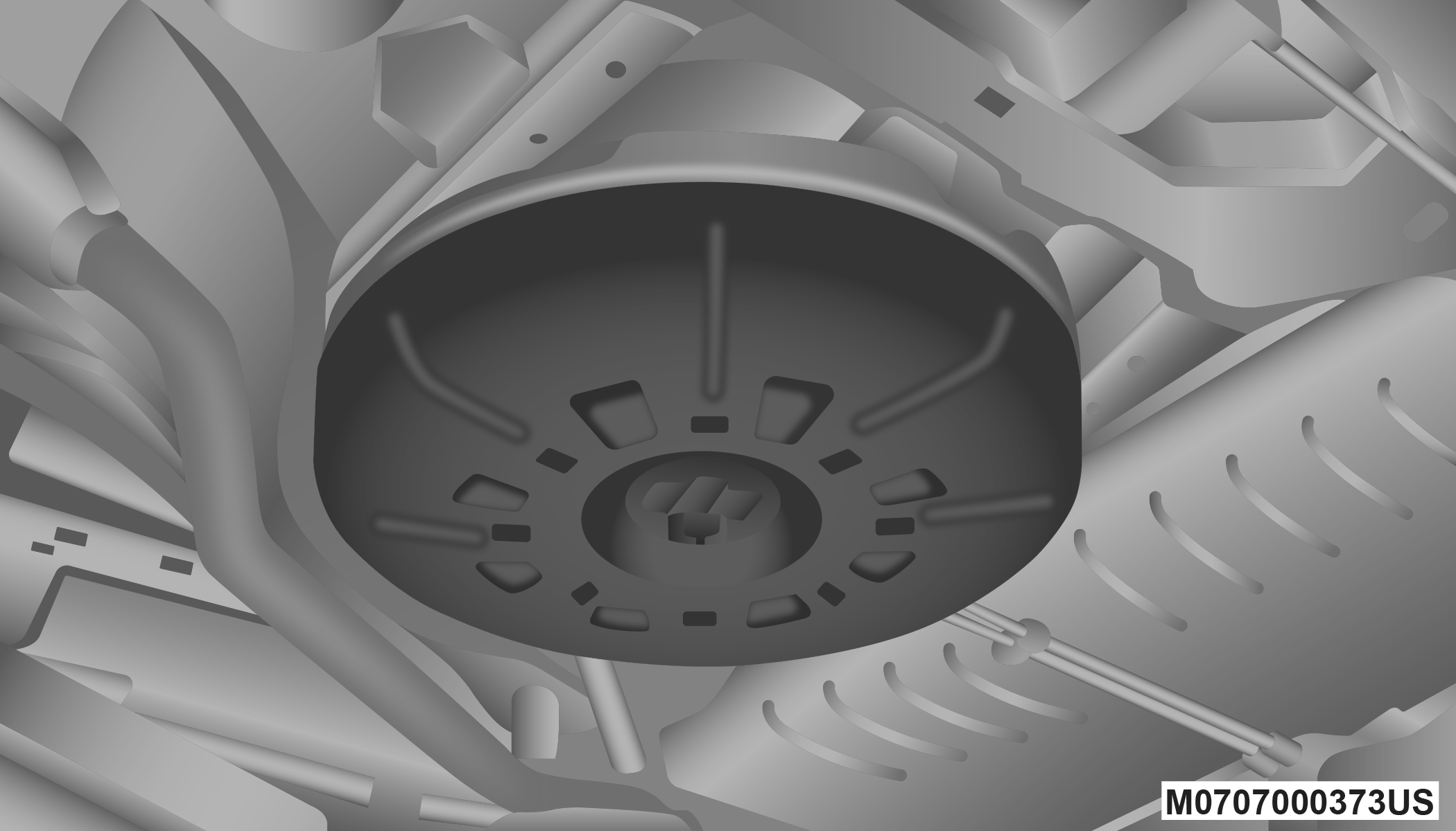
Stand the tire/cover assembly upright. Squeeze the winch retaining tabs together while simultaneously pushing them through the hole in the cover and the steel rim. This will free the winch cable from the spare tire.
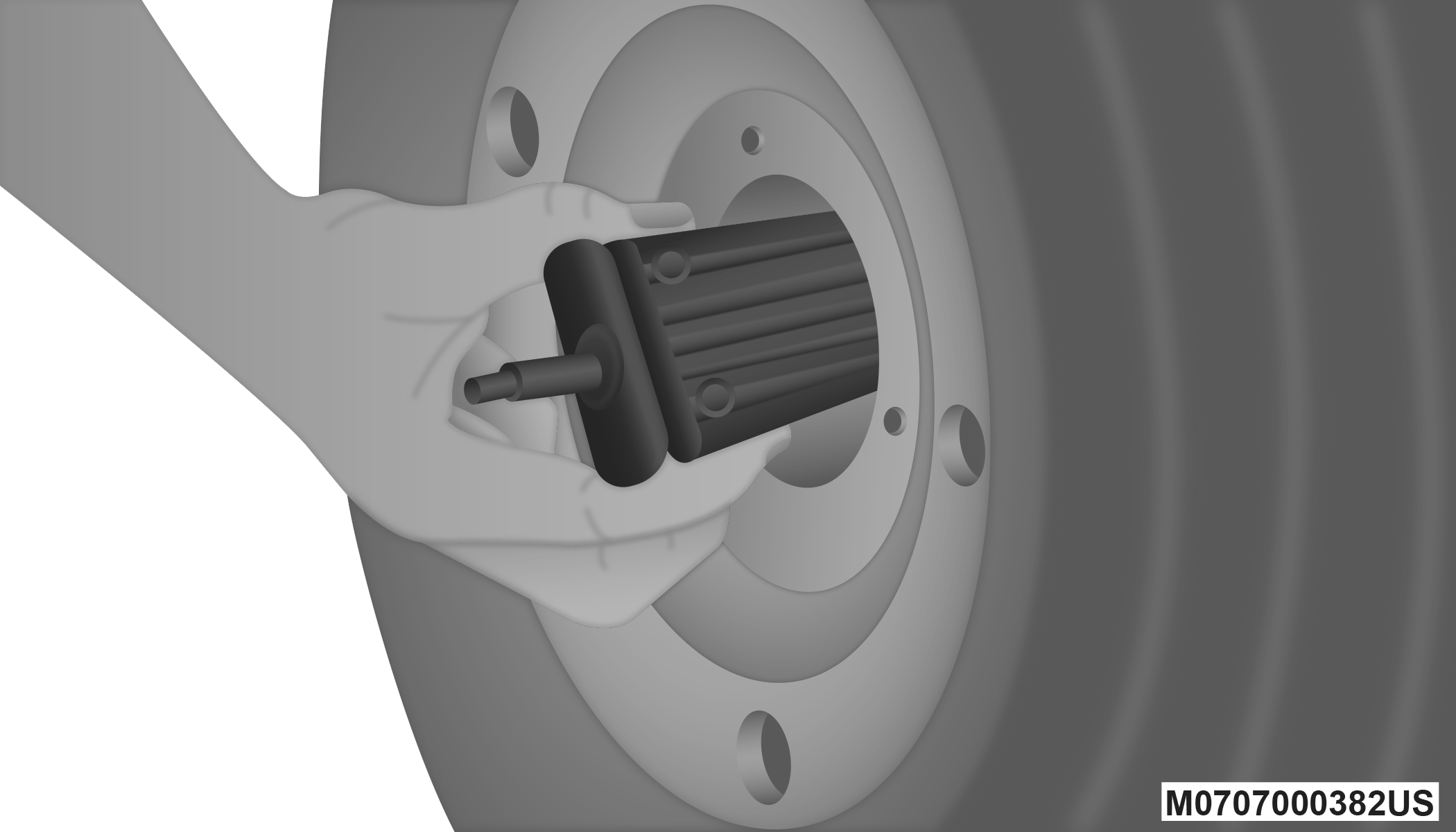
Removing Wheel Spacer
PREPARATIONS FOR JACKING
-
Park the vehicle on a firm, level surface. Avoid ice or slippery areas.
WARNING:
Do not attempt to change a tire on the side of the vehicle close to moving traffic. Pull far enough off the road to avoid being hit when operating the jack or changing the wheel.
-
Turn on the Hazard Warning Flashers.
-
Apply the parking brake.
-
Place the gear selector into PARK.
-
Turn OFF the ignition.
-
Block both the front and rear of the wheel diagonally opposite the jacking position. For example, if the driver’s front wheel is being changed, block the passenger’s rear wheel.
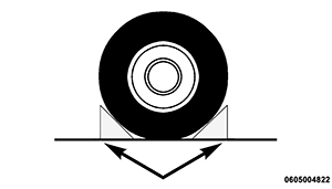
Wheel Blocked
Note:
Passengers should not remain in the vehicle when the vehicle is being raised or lifted.
JACKING INSTRUCTIONS
WARNING:
Carefully follow these tire changing warnings to help prevent personal injury or damage to your vehicle:
-
Always park on a firm, level surface as far from the edge of the roadway as possible before raising the vehicle.
-
Turn on the Hazard Warning Flashers.
-
Apply the parking brake firmly and shift an automatic transmission to PARK; a manual transmission to REVERSE.
-
Block the wheel diagonally opposite the wheel to be raised.
-
Never start or run the engine with the vehicle on a jack.
-
Do not let anyone sit in the vehicle when it is on a jack.
-
Do not get under the vehicle when it is on a jack. If you need to get under a raised vehicle, take it to a service center where it can be raised on a lift.
-
Only use the jack in the positions indicated and for lifting this vehicle during a tire change.
-
If working on or near a roadway, be extremely careful of motor traffic.
-
To assure that spare tires, flat or inflated, are securely stowed, spares must be stowed with the valve stem facing the ground.
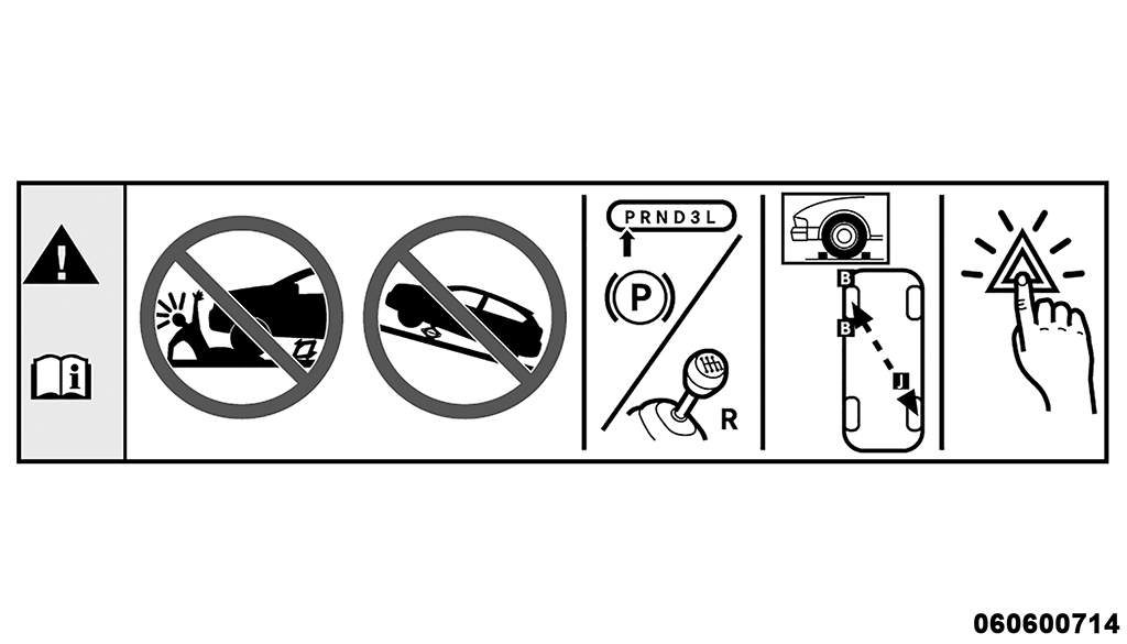
Jack Warning Label
CAUTION:
Do not attempt to raise the vehicle by jacking on locations other than those indicated in the Jacking Instructions for this vehicle.
Note:
Refer to the “Compact Spare Tire” section of “Tires” in “Servicing And Maintenance” for information about the compact spare tire, its use, and operation.
-
Loosen (but do not remove) the wheel lug nuts by turning them to the left one turn while the wheel is still on the ground.
-
There are two jack engagement locations on each side of the vehicle body. These locations are on the sill flange of the vehicle body.
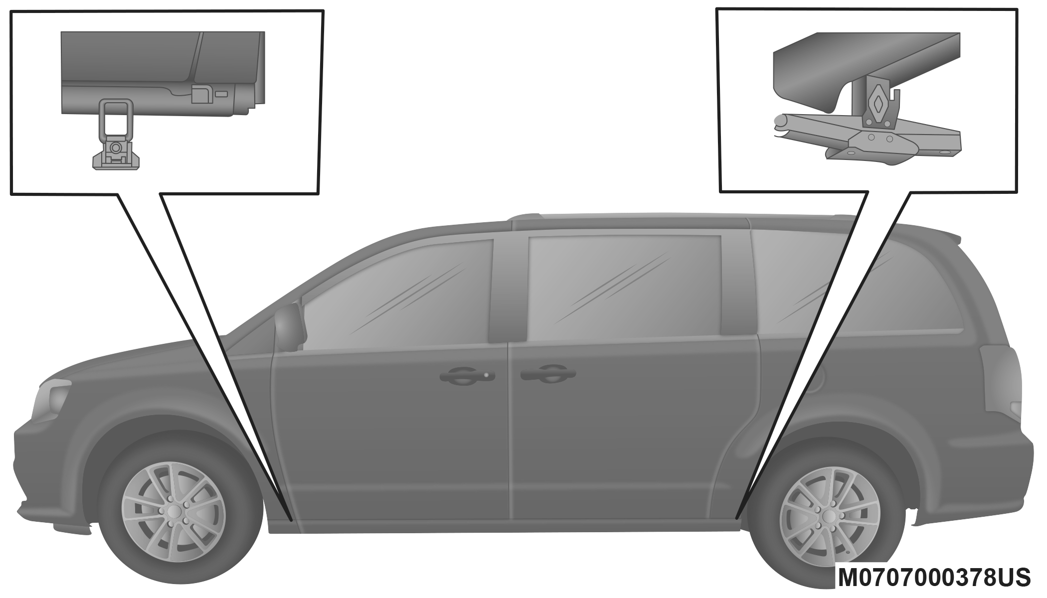
Jack Locations
CAUTION:
Do not attempt to raise the vehicle by jacking on locations other than those indicated.
Rear jack locations are between a pair of down-facing tabs on the sill flange of the vehicle side body.
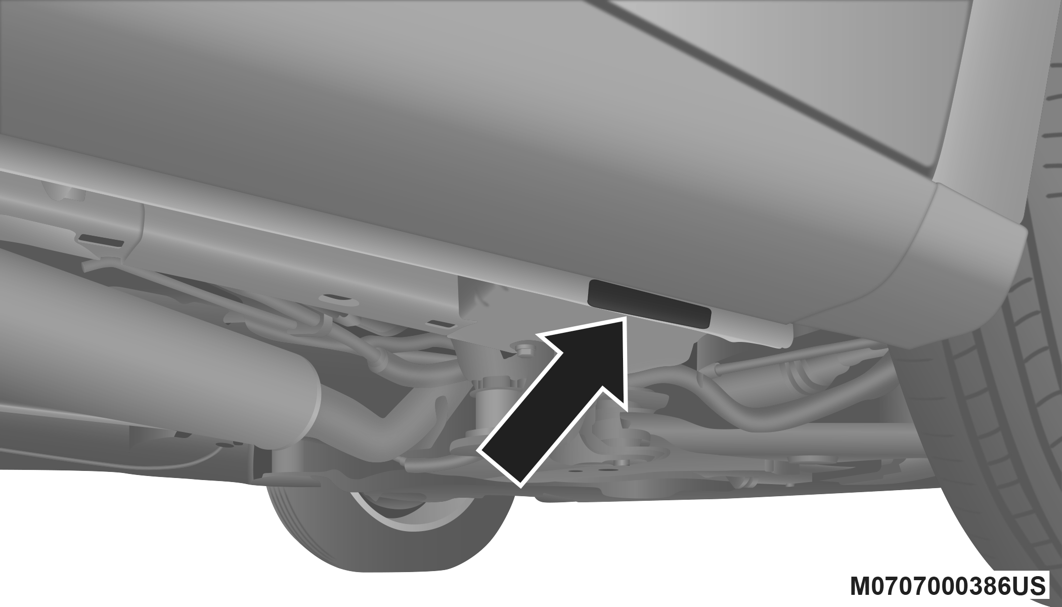
Front Lifting Point
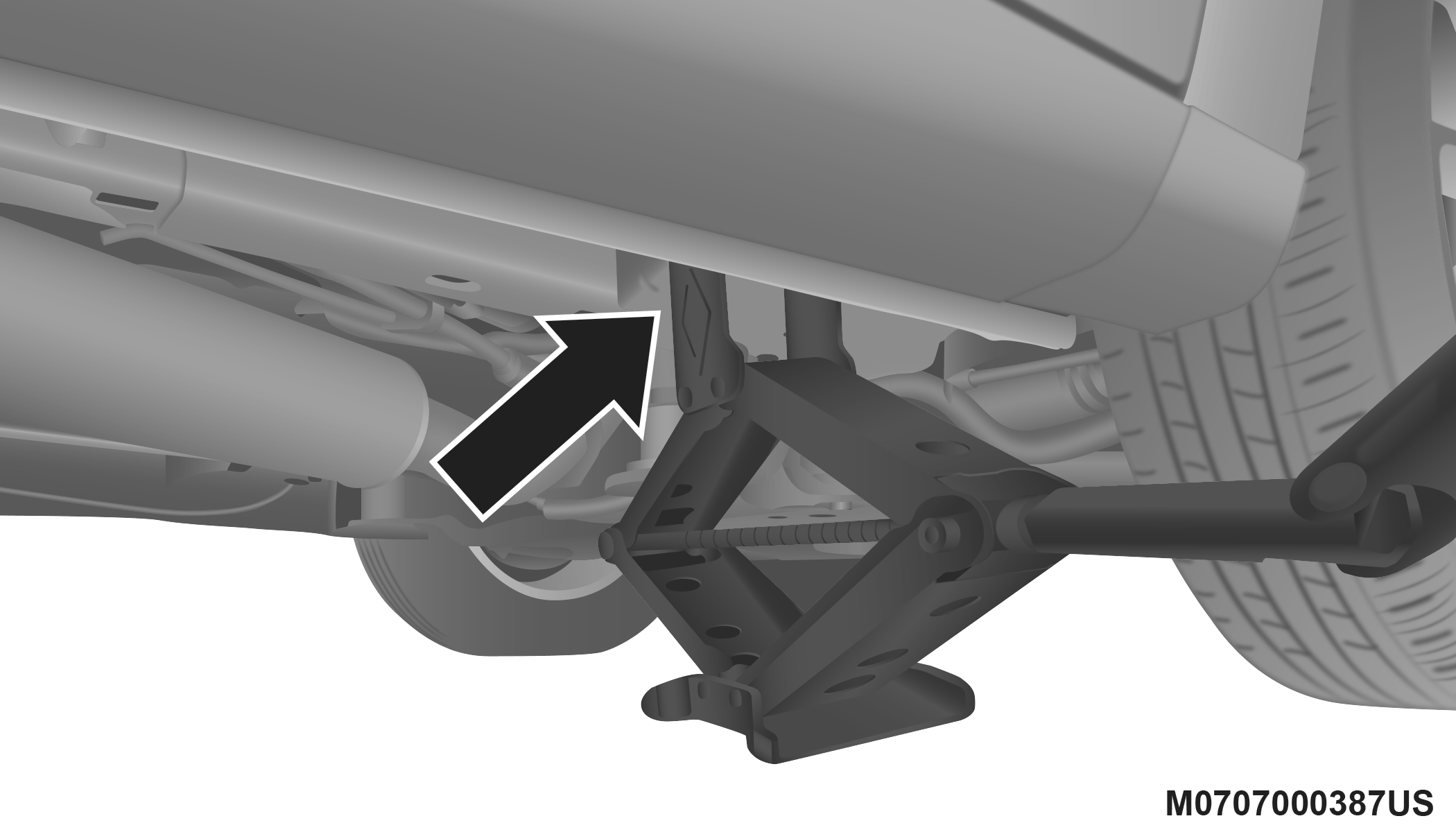
Front Jack Location
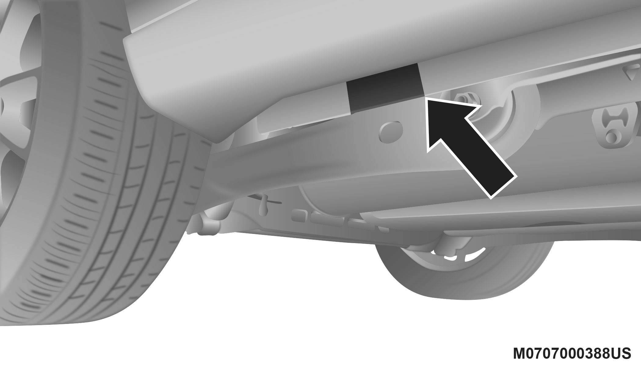
Rear Lifting Point
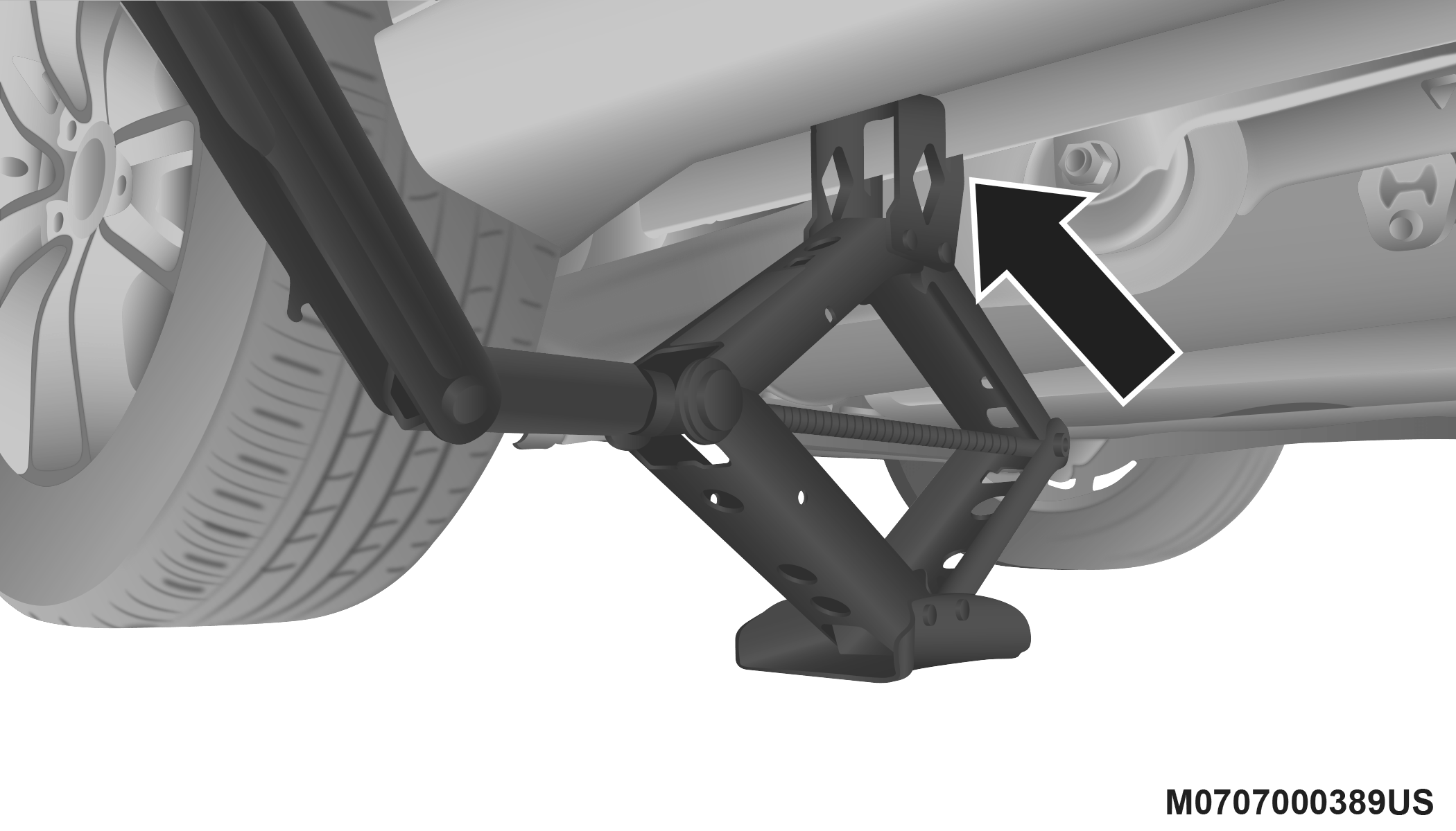
Rear Jack Location
Note:
In some situations the jack may need to be placed on its side in order to be pushed under the vehicle. Return the jack to its correct orientation once it is under the vehicle.
WARNING:
Being under a jacked-up vehicle is dangerous. The vehicle could slip off the jack and fall on you. You could be crushed. Never get any part of your body under a vehicle that is on a jack. If you need to get under a raised vehicle, take it to a service center where it can be raised on a lift.
-
Place the wrench on the jack screw and turn to the right until the jack head is properly engaged in the appropriate location. Do not raise the vehicle until you are sure the jack is securely engaged.
-
Raise the vehicle by turning the jack screw to the right, using the swivel wrench. Raise the vehicle only until the tire just clears the surface and enough clearance is obtained to install the compact spare tire. Minimum tire lift provides maximum stability.
WARNING:
Raising the vehicle higher than necessary can make the vehicle less stable. It could slip off the jack and hurt someone near it. Raise the vehicle only enough to remove the tire.
-
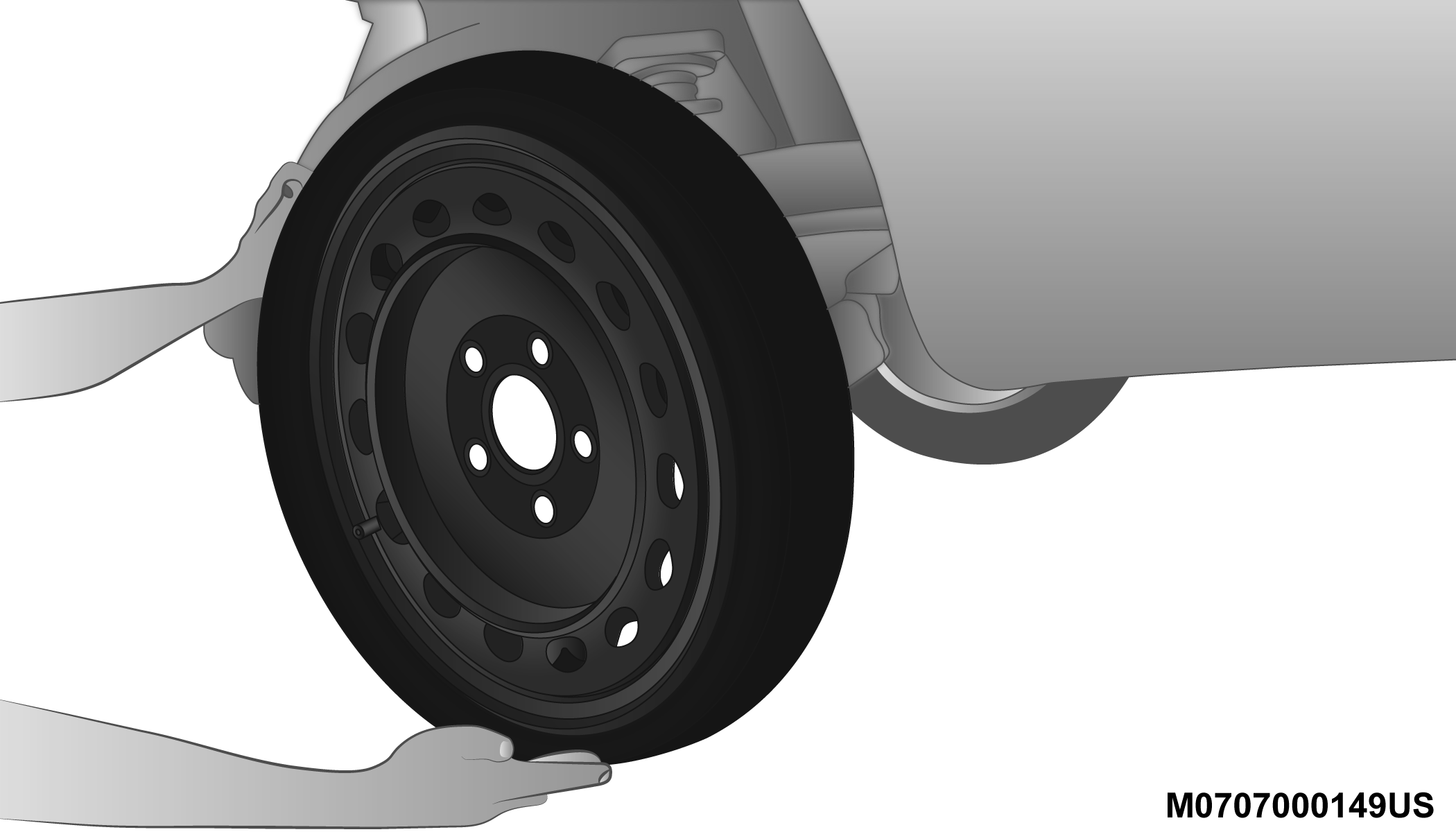
Remove the wheel lug nuts. For vehicles with wheel covers, remove the cover from the wheel by hand by holding down the wheel and pulling on convenient features on the cover. Do not pry the wheel cover off. Then pull the wheel off the hub.
-
Install the compact spare tire. Lightly tighten all the lug nuts until the wheel sits flush onto the hub and there is no play. The nuts will have to be fully tightened once the vehicle is lowered. Tightening an improperly seated wheel under vehicle load can damage the threads, cause vibration, and undermine safety.
CAUTION:
Be sure to mount the spare tire with the valve stem facing outward. The vehicle could be damaged if the spare tire is mounted incorrectly.
Mounting Compact Spare Tire
WARNING:
To avoid the risk of forcing the vehicle off the jack, do not tighten the wheel nuts fully until the vehicle has been lowered. Failure to follow this warning may result in serious injury.
Note:
Do not install the wheel cover on the compact spare.
-
Lower the vehicle by turning the jack screw to the left.
-
Finish tightening the lug nuts. Push down on the wrench while at the end of the handle for increased leverage. Tighten the lug nuts in a star pattern until each nut has been tightened twice. For correct lug nut torque refer to “Wheel And Tire Torque Specifications” in “Technical Specifications”. If in doubt about the correct tightness, have them checked with a torque wrench by an authorized dealer or at a service station.
-
Lower the jack to its fully-closed position.
WARNING:
A loose tire or jack thrown forward in a collision or hard stop could endanger the occupants of the vehicle. Always stow the jack parts and the spare tire in the places provided. Have the deflated (flat) tire repaired or replaced immediately.
-
Place the deflated (flat) tire and compact spare tire cover assembly in the rear cargo area. Do not stow the deflated tire in the compact spare tire location. Have the full-sized tire repaired or replaced, as soon as possible.
-
Stow the cable and wheel spacer before driving the vehicle. Reassemble the winch handle extensions to form a “T” and fit the winch T-handle over the drive nut. Rotate the nut to the right until the winch mechanism clicks at least three times.
Note:
Refer to the “Spare Tire Tools” section for instructions on assembling the T-handle.
-
Stow the jack, jack handle and winch handle tools back in the stowage compartment.
-
Check the compact spare tire pressure as soon as possible. Correct the tire pressure, as required.
SECURING THE COMPACT SPARE TIRE
-
Assemble the winch handle extensions to form a T-handle and fit the winch T-handle over the drive nut. Rotate the nut to the left until the winch mechanism stops turning freely. This will allow enough slack in the cable to allow you to pull the wheel spacer out from under the vehicle.
WARNING:
A loose compact spare tire/cover assembly, thrown forward in a collision or hard stop could endanger the occupants of the vehicle. Always stow the compact spare tire with the cover assembly in the place provided.
CAUTION:
The winch mechanism is designed for use with the winch T-handle only. Use of an air wrench or other power tools is not recommended and can damage the winch.
-
Assemble the winch handle extensions to form the spare tire hook, and pull the wheel spacer from under the vehicle.
-
Turn the compact spare tire so that the valve stem is down, and place the tire into the compact spare tire/cover assembly. Slide the wheel spacer through the center of the wheel and compact spare tire/cover assembly, so that the two retainer tabs snap out and engage the compact spare tire cover on the opposite side.
WARNING:
Verify that both retainer tabs of the wheel spacer have been properly extended through the center of the wheel and compact spare tire/cover assembly. Failure to properly engage both retainer tabs could result in loss of the compact spare tire and cover assembly, which will cause vehicle damage and may cause loss of vehicle control and serious personal injury.
CAUTION:
The compact spare tire/cover assembly must be used when the compact spare tire is stored. Failure to use this cover could drastically reduce the life of the compact spare tire.
-
Using the winch T-handle, rotate the drive nut to the right until the compact spare tire/cover assembly is drawn into place against the underside of the vehicle.
-
Continue to rotate the nut to the right until you hear the winch mechanism click three times. It cannot be overtightened. Check under the vehicle to ensure the compact spare tire/cover assembly is positioned correctly against the underside of the vehicle.
CAUTION:
The winch mechanism is designed specifically to stow a compact spare tire only. Do not attempt to use the winch to stow the full size deflated tire, or any other full-size tire, as the tire may not be held securely. Vehicle damage may result.
ROAD TIRE INSTALLATION
VEHICLES EQUIPPED WITH WHEEL COVERS
-
Mount the road tire on the axle.
-
To ease the installation process for steel wheels with wheel covers, install two lug nuts on the mounting studs which are on each side of the valve stem. Install the lug nuts with the cone shaped end of the nut toward the wheel. Lightly tighten the lug nuts.
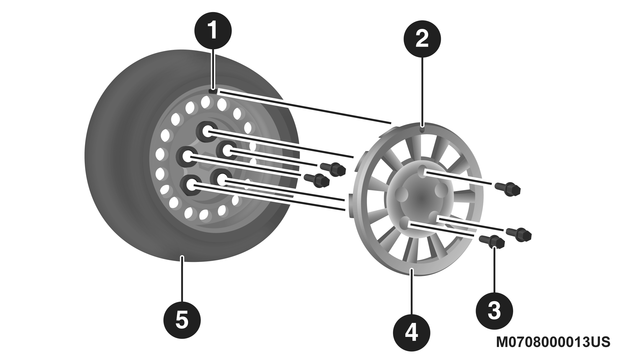
Tire And Wheel Cover Or Center Cap
1 — Valve Stem
2 — Valve Notch
3 — Wheel Lug Nut
4 — Wheel Cover
5 — Mounting Stud
-
Align the valve notch in the wheel cover with the valve stem on the wheel. Install the cover by hand, snapping the cover over the two lug nuts. Do not use a hammer or excessive force to install the cover.
-
Install the remaining lug nuts with the cone shaped end of the nut toward the wheel. Lightly tighten all the lug nuts until the wheel sits flush onto the hub and there is no play. The nuts will have to be fully tightened once the vehicle is lowered. Tightening an improperly seated wheel under vehicle load can damage the threads, cause vibration, and undermine safety.
WARNING:
To avoid the risk of forcing the vehicle off the jack, do not tighten the wheel nuts fully until the vehicle has been lowered. Failure to follow this warning may result in serious injury.
-
Lower the vehicle to the ground by turning the jack handle counterclockwise.
-
Finish tightening the lug nuts. Push down on the wrench while at the end of the handle for increased leverage. Tighten the lug nuts in a star pattern until each nut has been tightened twice. Refer to “Wheel And Tire Torque Specifications” in “Technical Specifications” for proper wheel lug nut torque. If in doubt about the correct tightness, have them checked with a torque wrench by an authorized dealer or at a service station.
-
After 25 miles (40 km) check the lug nut torque with a torque wrench to ensure that all lug nuts are properly seated against the wheel.
VEHICLES WITHOUT WHEEL COVERS
-
Mount the road tire on the axle.
-
Install the remaining lug nuts with the cone shaped end of the nut toward the wheel. Lightly tighten all the lug nuts until the wheel sits flush onto the hub and there is no play. The nuts will have to be fully tightened once the vehicle is lowered. Tightening an improperly seated wheel under vehicle load can damage the threads, cause vibration, and undermine safety.
WARNING:
To avoid the risk of forcing the vehicle off the jack, do not tighten the wheel nuts fully until the vehicle has been lowered. Failure to follow this warning may result in serious injury.
-
Lower the vehicle to the ground by turning the jack handle counterclockwise.
-
Finish tightening the lug nuts. Push down on the wrench while at the end of the handle for increased leverage. Tighten the lug nuts in a star pattern until each nut has been tightened twice. Refer to “Wheel And Tire Torque Specifications” in the “Technical Specifications” section for proper wheel lug nut torque. If in doubt about the correct tightness, have them checked with a torque wrench by an authorized dealer or at a service station.
-
After 25 miles (40 km) check the lug nut torque with a torque wrench to ensure that all lug nuts are properly seated against the wheel.
Download Manual