Fuses
WARNING:
-
When replacing a blown fuse, always use an appropriate replacement fuse with the same amp rating as the original fuse. Never replace a fuse with another fuse of higher amp rating. Never replace a blown fuse with metal wires or any other material. Do not place a fuse inside a circuit breaker cavity or vice versa. Failure to use proper fuses may result in serious personal injury, fire and/or property damage.
-
Before replacing a fuse, make sure that the ignition is off and that all the other services are switched off and/or disengaged.
-
If the replaced fuse blows again, contact an authorized dealer.
-
If a general protection fuse for safety systems (air bag system, braking system), power unit systems (engine system, transmission system) or steering system blows, contact an authorized dealer.
GENERAL INFORMATION
The fuses protect electrical systems against excessive current.
When a device does not work, you must check the fuse element inside the blade fuse for a break/melt.
Also, please be aware that when using power outlets for extended periods of time with the engine off may result in vehicle battery discharge.
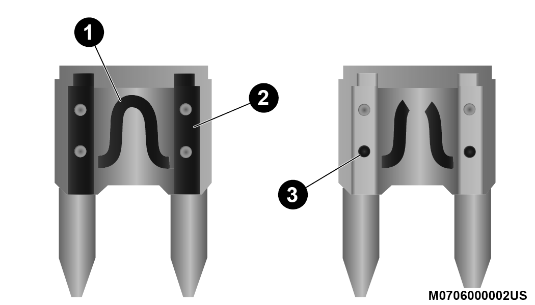
Blade Fuses
| 1 — Fuse Element |
| 2 — Blade Fuse with a good/functional fuse element. |
| 3 — Blade fuse with a bad/not functional fuse element (blown fuse). |
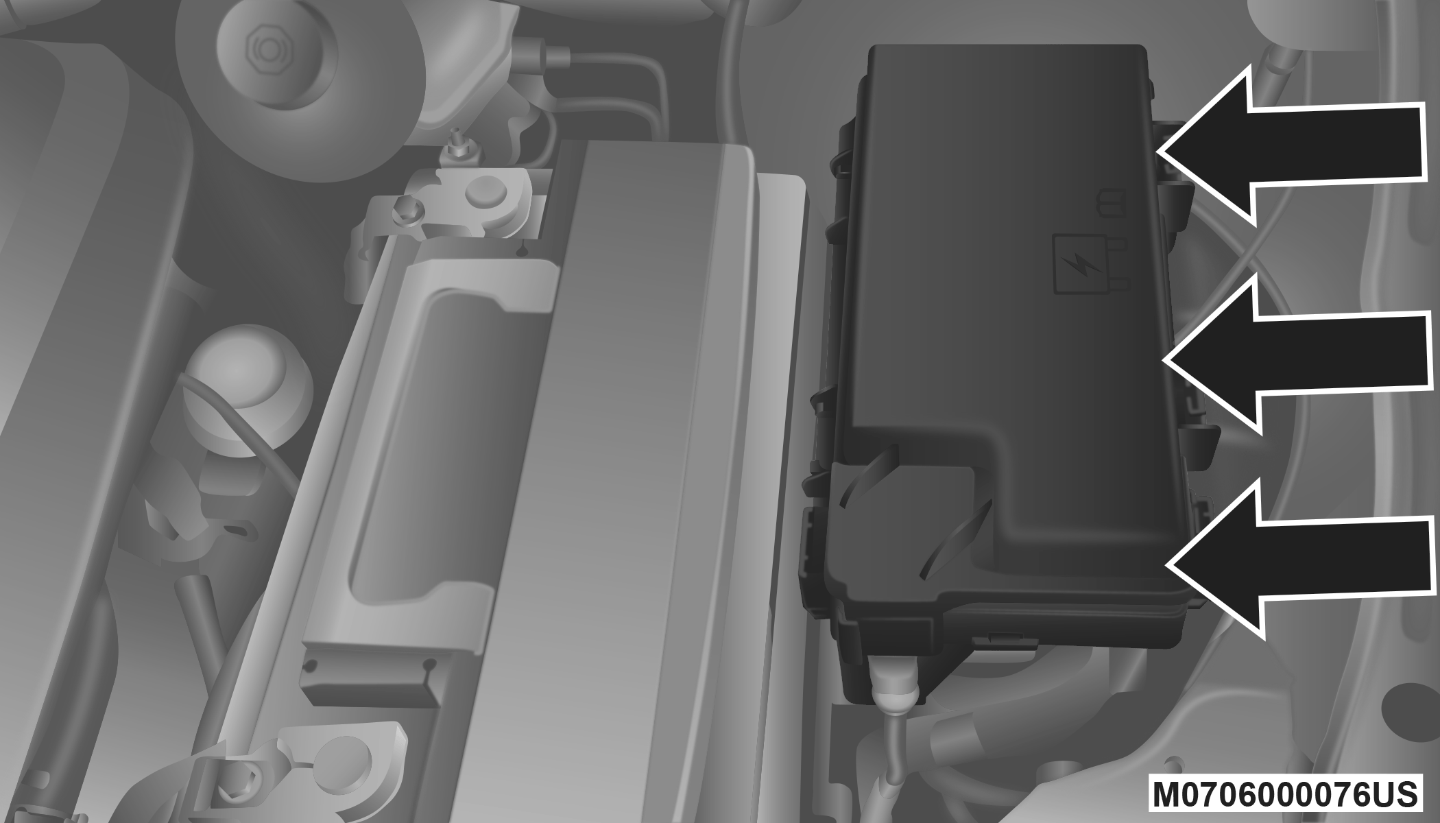
TOTALLY INTEGRATED POWER MODULE (FUSES)
The Totally Integrated Power Module is located in the engine compartment near the battery. Refer to the applicable “Engine Compartment” illustration in this section. This center contains cartridge fuses and mini-fuses. A label that identifies each component may be printed or embossed on the inside of the cover.
Totally Integrated Power Module
CAUTION:
-
When installing the Totally Integrated Power Module cover, it is important to ensure the cover is properly positioned and fully latched. Failure to do so may allow water to get into the Integrated Power Module, and possibly result in a electrical system failure.
-
When replacing a blown fuse, it is important to use only a fuse having the correct amperage rating. The use of a fuse with a rating other than indicated may result in a dangerous electrical system overload. If a properly rated fuse continues to blow, it indicates a problem in the circuit that must be corrected.
The numbers inside the Totally Integrated Power Module (TIPM) cover correspond to the following table.
|
Cavity |
Cartridge Fuse |
Mini-Fuse |
Description |
|
J1 |
40 Amp Green |
– |
Power Folding Seat |
|
J2 |
30 Amp Pink |
– |
Power Liftgate Module |
|
J3 |
30 Amp Pink |
– |
Rear Door Module |
|
J4 |
25 Amp Clear |
– |
Driver Door Node |
|
J5 |
25 Amp Clear |
– |
Passenger Door Node |
|
J6 |
40 Amp Green |
– |
Antilock Brakes Pump/Stability Control System |
|
J7 |
30 Amp Pink |
– |
Antilock Brakes Valve/Stability Control System |
|
J8 |
40 Amp Green |
– |
Power Memory Seat – If Equipped |
|
J9 |
– |
– |
Not Used |
|
J10 |
30 Amp Pink |
– |
Headlamp Wash/Manifold Tuning Valve – If Equipped |
|
J11 |
30 Amp Pink |
– |
Power Sliding Door Module/Anti–Theft Module – If Equipped |
|
J12 |
30 Amp Pink |
– |
HVAC Rear Blower, Radiator Fan Motor |
|
J13 |
60 Amp Yellow |
– |
Ignition Off Draw (IOD) – Main |
|
J14 |
40 Amp Green |
– |
Rear Window Defogger |
|
J15 |
40 Amp Green |
– |
Front Blower |
|
J17 |
40 Amp Green |
– |
Starter Solenoid |
|
J18 |
20 Amp Blue |
– |
Powertrain Control Module Trans Range |
|
J19 |
60 Amp Yellow |
– |
Radiator Fan |
|
J20 |
30 Amp Pink |
– |
Front Wiper LO/HI |
|
J21 |
20 Amp Blue |
– |
Front/Rear Washer |
|
J22 |
25 Amp Clear |
– |
Sunroof Module |
|
M1 |
– |
15 Amp Blue |
Rear Center Brake Lamp/Brake Switch |
|
M2 |
– |
20 Amp Yellow |
Front Fog Lamps |
|
M3 |
– |
20 Amp Yellow |
Vacuum Pump Motor |
|
M5 |
– |
25 Amp Clear |
Inverter |
|
M6 |
– |
20 Amp Yellow |
Power Outlet #1 (ACC), Rain Sensor, Cigar Lighter (Instrument Panel or with Console Rear) |
|
M7 |
– |
20 Amp Yellow |
Power Outlet #2 (BATT/ACC SELECT) – Center Seat or with Console Rear |
|
M8 |
– |
20 Amp Yellow |
Front Heated Seat — If Equipped |
|
M9 |
– |
20 Amp Yellow |
Rear Heated Seat — If Equipped |
|
M10 |
– |
15 Amp Blue |
Ignition Off Draw — Video System, Satellite Radio, DVD, Hands-Free Module, Universal Garage Door Opener, Vanity Lamp, Streaming Video Module — If Equipped |
|
M11 |
– |
10 Amp Red |
Climate Control System |
|
M12 |
– |
30 Amp Green |
Amplifier/Radio |
|
M13 |
– |
20 Amp Yellow |
Instrument Cluster, SIREN, Clock Module, Multifunction Control Switch – If Equipped |
|
M14 |
– |
20 Amp Yellow |
Trailer Tow — If Equipped |
|
M15 |
– |
20 Amp Yellow |
Rear View Mirror, Instrument Cluster, Multifunction Control Switch, Tire Pressure Monitor |
|
M16 |
– |
10 Amp Red |
Airbag Module/Occupant Classification Module |
|
M17 |
– |
15 Amp Blue |
Left Tail/License/Park Lamp, Running Lamps |
|
M18 |
– |
15 Amp Blue |
Right Tail/Park/Run Lamp |
|
M19 |
– |
25 Amp Clear |
Powertrain |
|
M20 |
– |
15 Amp Blue |
Instrument Cluster Interior Light, Switch Bank, Steering Column Module, Switch Steering Wheel |
|
M21 |
– |
20 Amp Yellow |
Powertrain |
|
M22 |
– |
10 Amp Red |
Horn |
|
M23 |
– |
10 Amp Red |
Horn |
|
M24 |
– |
25 Amp Clear |
Rear Wiper |
|
M25 |
– |
20 Amp Yellow |
Fuel Pump |
|
M26 |
– |
10 Amp Red |
Power Mirror Switch, Driver Window Switch |
|
M27 |
– |
10 Amp Red |
Wireless Control Module, Keyless Entry Module |
|
M28 |
– |
10 Amp Red |
Powertrain, Transmission Control Module |
|
M29 |
– |
10 Amp Red |
Occupant Classification Module |
|
M30 |
– |
15 Amp Blue |
Diagnostic Feed |
|
M31 |
– |
20 Amp Yellow |
Back-Up Lamps |
|
M32 |
– |
10 Amp Red |
Airbag Module, THATCHUM — If Equipped |
|
M33 |
– |
10 Amp Red |
Powertrain |
|
M34 |
– |
10 Amp Red |
Park Assist, Heater Climate Control Module, Headlamp Wash, Compass, Rear Camera, Door Lamps, Flashlight, Relay Diesel Cabin Heater |
|
M35 |
– |
10 Amp Red |
Heated Mirrors |
|
M36 |
– |
20 Amp Yellow |
Power Outlet #3 (Instrument Panel Or With Console Center) |
|
M37 |
– |
10 Amp Red |
Antilock Brakes, Stability Control, Stop Lamp, Fuel Pump |
|
M38 |
– |
25 Amp Clear |
Door Lock/Unlock Motors, Liftgate Lock/Unlock Motors |
The power windows are fused by a 25 Amp circuit breaker located in the Totally Integrated Power Module.
Download Manual