Around View® Monitor (if so equipped)
With the ignition switch in the ON position, press the CAMERA button or move the shift lever to the R (Reverse) position to operate the Around View Monitor. The monitor displays various views of the position of the vehicle in a split screen format.
WARNING
|
Available views:
- Bird’s-Eye View
The surrounding view of the vehicle from above. - Front-Side View
The view around and ahead of the front passenger’s side wheel. - Front View
The view to the front of the vehicle. - Rear View
The view to the rear of the vehicle.
The system is designed as an aid to the driver in situations such as slot parking or parallel parking.
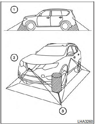
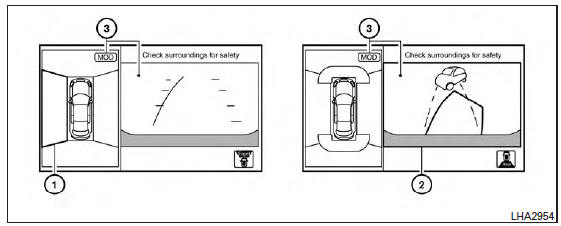
There are some areas where the system will not show objects. When in the front or rearview display, an object below the bumper or on the ground may not be viewed 1 . When in the bird’s-eye view, a tall object near the seam of the camera viewing areas will not appear in the monitor 2 .
| CAUTION
Do not scratch the camera lens when cleaning dirt or snow from the front of the camera. |
Available views
WARNING
|
Front view
Front and rear view
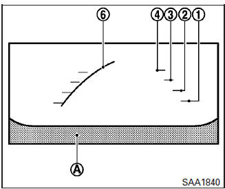
Guiding lines, which indicate the vehicle width and distance to objects with reference to the vehicle body line A , are displayed on the monitor.
Distance guide lines:
Indicate distances from the vehicle body:
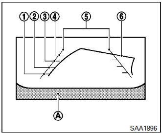
- Red line 1 : approximately 1.5 ft (0.5 m)
- Yellow line 2 : approximately 3 ft (1 m)
- Green line 3 : approximately 7 ft (2 m)
- Green line 4 : approximately 10 ft (3 m)
Rearview
Vehicle width guide lines 5 :
Indicate the vehicle width when backing up.
Predictive course lines 6 :
Indicate the predictive course when operating the vehicle. The predictive course lines will be displayed on the monitor when the steering wheel is turned. The predictive course lines will move depending on how much the steering wheel is turned and will not be displayed while the steering wheel is in the neutral position.
The front view will not be displayed when the vehicle speed is above 6 mph (10 km/h).
NOTE: When the monitor displays the front view and the steering wheel turns about 90 degrees or less from the neutral position, both the right and left predictive course lines 6 are displayed. When the steering wheel turns about 90 degrees or more, a line is displayed only on the opposite side of the turn.
WARNING
|
Bird’s-eye view
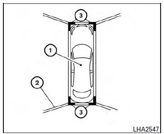
The bird’s-eye view shows the overhead view of the vehicle, which helps confirm the vehicle position and the predicted course to a parking space.
The vehicle icon 1 shows the position of the vehicle. Note that the distance between objects viewed in the bird’s-eye view differs from the actual distance.
The areas that the cameras cannot cover 2 are indicated in black.
After the ignition switch is placed in the ON position, the non-viewable area 2 is highlighted in yellow for 3 seconds after the bird’s-eye view is displayed. In addition, the non-viewable corners are displayed in red and blink for the first 3 seconds 3 to remind the driver to be cautious.
WARNING
|
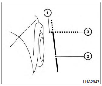
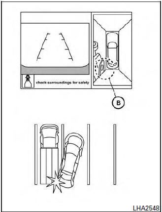
Front-side view
Guiding lines:
Guiding lines that indicate the width and the front end of the vehicle are displayed on the monitor.
The front-of-vehicle line 1 shows the front part of the vehicle.
The side-of-vehicle line 2 shows the vehicle width including the outside mirror.
The extensions 3 of both the front 1 and side 2 lines are shown with a green dotted line.
CAUTION
|
Difference between predictive and actual distances
Backing up on a steep uphill
When backing up the vehicle up a hill, the distance guide lines and the vehicle width guide lines are shown closer than the actual distance.
For example, the display shows 3 ft (1.0 m) to the place A , but the actual 3 ft (1.0 m) distance on the hill is the place B . Note that any object on the hill is further than it appears on the monitor.
Backing up on a steep downhill
When backing up the vehicle down a hill, the distance guide lines and the vehicle width guide lines are shown farther than the actual distance.
For example, the display shows 3 ft (1.0 m) to the place A , but the actual 3 ft (1.0 m) distance on the hill is the place B . Note that any object on the hill is closer than it appears on the monitor
Backing up near a projecting object
The predicted course lines A do not touch the object in the display. However, the vehicle may hit the object if it projects over the actual backing up course.
Backing up near a projecting object
There may be a small distance visible between the vehicle and the object in the bird-eye view on the display B .
Backing up behind a projecting object
The position C is shown farther than the position B in the display. However, the position C is actually at the same distance as the position A .
The vehicle may hit the object when backing up to the position A if the object projects over the actual backing up course.
How to switch the display
With the ignition switch in the ON position, press the CAMERA button or move the shift lever to the R (Reverse) position to operate the Around View Monitor.
The Around View Monitor displays different split screen views depending on the position of the shift lever. Press the CAMERA button to switch between the available views.
If the shift lever is in the R (Reverse) position, the available views are:
- Rear view/bird’s-eye view split screen
- Rear view/front-side view split screen
If the shift lever is in the P (Park) position, the available views are:
- Front view/bird’s-eye view split screen
- Front view/front-side view split screen
If the shift selector is in the D (Drive) position, the only available view is front view/front-side view split screen.
The display will switch from the Around View Monitor screen when:
- The shift lever is in the D (Drive) position and the vehicle speed increases above approximately 6 mph (10 km/h)
- A different screen is selected.
How to adjust the Camera Settings
To adjust the Display ON/OFF/AUTO, Brightness, Color and Contrast of the Around View Monitor, press the { } button with the Around View Monitor on followed by the SETTINGS key on the touch-screen. Next, touch the SYSTEM key and then the CAMERA DISPLAY SETTINGS key on the touch-screen.
Do not adjust any of the CAMERA DISPLAY SETTINGS of the Around View Monitor while the vehicle is moving. Make sure the parking brake is firmly applied.
Moving Object Detection (MOD) (if so equipped)
The MOD system can inform the driver of moving objects behind the vehicle when backing out of garages, maneuvering in parking lots and in other such instances.
The MOD system detects moving objects by using image processing technology on the image shown in the display.
The MOD system operates in the following conditions when the camera view is displayed:
- When the shift lever is in the P (Park) or N (Neutral) position and the vehicle is stopped, theMODsystem detects the moving objects in the bird’s-eye view. The MOD system will not operate if the outside mirror is moving in or out or if either door is opened.
- When the shift lever is in the D (Drive) position and the vehicle speed is below approximately 5 mph (8 km/h), the MOD system detects moving objects in the front view or front-wide view.
- When the shift lever is in the R (Reverse) position and the vehicle speed is below approximately 5 mph (8 km/h), the MOD system detects moving objects in the rear view.
The MOD system will not operate if the liftgate is open.
The MOD system does not detect moving objects in the front-side view. TheMODsystem icon is not displayed on the screen when in this view.
WARNING
|
If the MOD system detects the moving objects surrounding the vehicle, the yellow frame will be displayed on the camera image and a chime sounds.
When the MOD system detects a moving object surrounding the vehicle, the yellow frame will be displayed on the view where the objects are detected and a chime will sound once. While the MOD system continues to detect moving objects, the yellow frame continues to be displayed.
In the bird’s-eye view, the yellow 1 is displayed on each camera image (front, rear, right, left) depending on where moving objects are detected.
The yellow frame 2 is displayed on each view in the front view, rear view modes.
A blue MOD icon is displayed in the view where theMODsystem is operative. A grayMODicon is displayed in the view where the MOD system is not operative.
If theMODsystem is turned off, theMODicon 3 is not displayed.
Turning the MOD system on or off
The MOD system is turned on or off using the settings menu in the vehicle information display.
A blue MOD icon is displayed if the MOD is operative.
A gray MOD icon is displayed if the MOD is not operative.
- Press the
 button until “Settings” displays in the vehicle information display. Use the
  to select “Driver Assistance”.
Then press the ENTER button.
- Select “Parking Aids”, and press the ENTER button.
- To set the MOD system to on or off, use the
 buttons to navigate in the menu and use the ENTER button to select or change an item:
- To turn off the warning, use the ENTER button to check box for “Moving Object” If the MOD system is turned off, the MOD icon is not displayed.
Moving Object Detection (MOD) malfunction
WARNING
|
When the orange MOD icon is displayed in the view, the system is not functioning properly. This will not hinder normal driving operation but the system should be inspected by a NISSAN dealer.
Camera Maintenance
If dirt, rain or snow accumulates on the camera, theMODsystem may not operate properly. Clean the camera.
Operating tips
CAUTION
|
- The screen displayed on the Around View Monitor will automatically return to the previous screen 3 minutes after the CAMERA button has been pressed with the shift lever in a position other than the R (Reverse) position.
- When the view is switched, the display images on the screen may be displayed in some delay.
- When the temperature is extremely high or low, the screen may not display objects clearly. This is not a malfunction.
- When strong light directly shines on the camera, objects may not be displayed clearly. This is not a malfunction.
- The screen may flicker under fluorescent light. This is not a malfunction.
- The colors of objects on the Around View Monitor may differ somewhat from the actual color of objects. This is not a malfunction.
- Objects on the Around View Monitor may not be clear and the color of the object may differ in a dark environment. This is not a malfunction.
- There may be differences in sharpness between each camera view of the bird’s-eye view.
- If dirt, rain or snow accumulates on the camera, the Around View Monitor may not display objects clearly. Clean the camera.
- Do not use wax on the camera lens. Wipe off any wax with a clean cloth that has been dampened with a mild detergent diluted with water.
Download Manual