Vehicle Maintenance
An authorized dealer has the qualified service personnel, special tools, and equipment to perform all service operations in an expert manner. Service Manuals are available which include detailed service information for your vehicle. Refer to these Service Manuals before attempting any procedure yourself.
Note:
Intentional tampering with emissions control systems may void your warranty and could result in civil penalties being assessed against you.
WARNING:
You can be badly injured working on or around a motor vehicle. Only do service work for which you have the knowledge and the proper equipment. If you have any doubt about your ability to perform a service job, take your vehicle to a competent mechanic.
ENGINE OIL
ENGINE OIL SELECTION
For engine oil selection .
AMERICAN PETROLEUM INSTITUTE (API) APPROVED ENGINE OIL
These symbols mean that the oil has been certified by the API. The manufacturer only recommends API trademark oils.
 The API Starburst trademark certifies 0W-20, 0W-30 and 5W-30 engine oils.
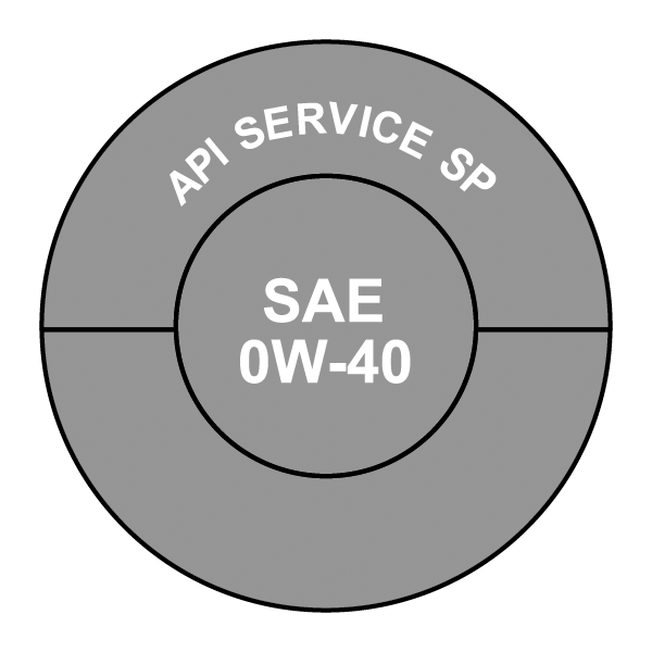 The API Donut trademark certifies 0W-40 and 5W-40 engine oil.
CAUTION:
Do not use chemical flushes in your engine oil as the chemicals can damage your engine. Such damage is not covered by the New Vehicle Limited Warranty.
SYNTHETIC ENGINE OILS
Your engine was designed for synthetic engine oils, only use synthetic API approved engine oils.
Synthetic engine oils which do not have both the correct API trademark and the correct SAE viscosity grade numbers should not be used.
MATERIALS ADDED TO ENGINE OIL
The manufacturer strongly recommends against the addition of any additives (other than leak detection dyes) to the engine oil. Engine oil is an engineered product and its performance may be impaired by supplemental additives.
DISPOSING OF USED ENGINE OIL AND OIL FILTERS
Care should be taken in disposing of used engine oil and oil filters from your vehicle. Used oil and oil filters, indiscriminately discarded, can present a problem to the environment. Contact an authorized dealer, service station or governmental agency for advice on how and where used oil and oil filters can be safely discarded in your area.
ENGINE OIL FILTER
The engine oil filter should be replaced with a new filter at every engine oil change.
Engine Oil Filter Selection
A full-flow type disposable oil filter should be used for replacement. The quality of replacement filters varies considerably. Only high quality Mopar® certified filters should be used.
ENGINE AIR CLEANER FILTER
For the proper maintenance intervals .
WARNING:
The air induction system (air cleaner, hoses, etc.) can provide a measure of protection in the case of engine backfire. Do not remove the air induction system (air cleaner, hoses, etc.) unless such removal is necessary for repair or maintenance. Make sure that no one is near the engine compartment before starting the vehicle with the air induction system (air cleaner, hoses, etc.) removed. Failure to do so can result in serious personal injury.
Engine Air Cleaner Filter Selection
The quality of replacement filters varies considerably. Only high quality Mopar® certified filters should be used.
AIR CONDITIONER MAINTENANCE
For best possible performance, your air conditioner should be checked and serviced by an authorized dealer at the start of each warm season. This service should include cleaning of the condenser fins and a performance test. Drive belt tension should also be checked at this time.
Note:
Use only refrigerants and compressor lubricants approved by the manufacturer for your air conditioning system. Some unapproved refrigerants are flammable and can explode, injuring you. Other unapproved refrigerants or lubricants can cause the system to fail, requiring costly repairs. Refer to the Warranty Information Book for further warranty information.
Use only refrigerants and compressor lubricants approved by the manufacturer for your air conditioning system. Some unapproved refrigerants are flammable and can explode, injuring you. Other unapproved refrigerants or lubricants can cause the system to fail, requiring costly repairs.
The air conditioning system contains refrigerant under high pressure. To avoid risk of personal injury or damage to the system, adding refrigerant or any repair requiring lines to be disconnected should be done by an experienced technician.
CAUTION:
Do not use chemical flushes in your air conditioning system as the chemicals can damage your air conditioning components. Such damage is not covered by the New Vehicle Limited Warranty.
REFRIGERANT RECOVERY AND RECYCLING — R–1234YF
R–1234yf Air Conditioning Refrigerant is a hydrofluoroolefin (HFO) that is endorsed by the Environmental Protection Agency and is an ozone-friendly substance with a low global-warming potential. The manufacturer recommends that air conditioning service be performed by an authorized dealer using recovery and recycling equipment.
Note:
Use only the manufacturer approved A/C system PAG compressor oil, and refrigerants.
CABIN AIR CLEANER
See an authorized dealer for service.
BODY LUBRICATION
Locks and all body pivot points, including such items as seat tracks, door hinge pivot points and rollers, liftgate, tailgate, decklid, sliding doors and hood hinges, should be lubricated periodically with a lithium-based grease, such as Mopar® Spray White Lube to ensure quiet, easy operation and to protect against rust and wear. Prior to the application of any lubricant, the parts concerned should be wiped clean to remove dust and grit; after lubricating, excess oil and grease should be removed. Particular attention should also be given to hood latching components to ensure proper function. When performing other underhood services, the hood latch, release mechanism and safety catch should be cleaned and lubricated.
The external lock cylinders should be lubricated twice a year, preferably in the Autumn and Spring. Apply a small amount of a high quality lubricant, such as Mopar® Lock Cylinder Lubricant directly into the lock cylinder.
WINDSHIELD WIPER BLADES
Clean the rubber edges of the wiper blades and the windshield periodically with a sponge or soft cloth and a mild nonabrasive cleaner. This will remove accumulations of salt or road film.
Operation of the wipers on dry glass for long periods may cause deterioration of the wiper blades. Always use washer fluid when using the wipers to remove salt or dirt from a dry windshield.
Avoid using the wiper blades to remove frost or ice from the windshield. Keep the blade rubber out of contact with petroleum products such as engine oil, gasoline, etc.
Note:
Life expectancy of wiper blades varies depending on geographical area and frequency of use. Poor performance of blades may be present with chattering, marks, water lines or wet spots. If any of these conditions are present, clean the wiper blades or replace as necessary.
SERVICE POSITION STRATEGY
The service position allows the wiper blades to be placed in a position that allows the wiper blades to be easily changed.
To enable the Service Position Strategy, the wipers must be in the Park position before placing the ignition in the OFF position.
Service mode must be activated within two minutes after the ignition is placed in the OFF position.
To have a correct activation of strategy, the Service Position command (antipanic) must be active for at least half a second.
At every valid activation of Service Position command, the wiper blades are activated for 250 ms.
The Service Position command can be repeated several times to bring the blades into the desired position, up to a maximum of three times.
After three subsequent activations the strategy is disabled.
Function Deactivation:
The functionality is reset if:
The ignition is turned to the MAR/RUN position.
Number of subsequent activations is three.
Two minutes timer has expired after turning the ignition OFF.
Note:
When turning the ignition ON, the blades will go into the parking position.
FRONT WIPER BLADE REMOVAL/INSTALLATION
-
Lift the front wiper arm upward to raise the wiper blade off of the windshield.
-
Push the release button on the arm of the wiper blade.
-
Push the wiper blade up and remove it.
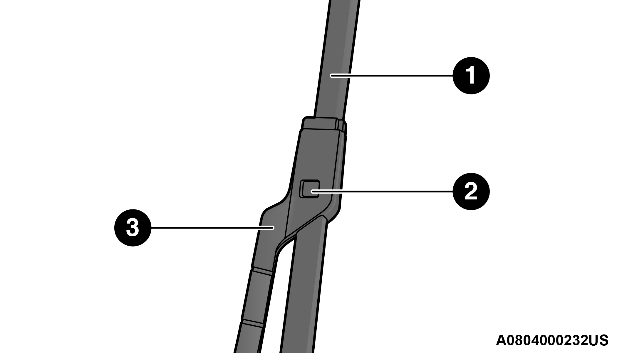
1 — Wiper Blade
2 — Release Button
3 — Wiper Arm
-
Install the wiper blade and firmly push the wiper blade until it snaps into place.
REAR WIPER BLADE REMOVAL/INSTALLATION
-
Carefully lift the rear wiper arm upward to raise the wiper blade off of the liftgate glass.
-
Grab and hold the wiper arm closest to the wiper blade end while pushing the wiper blade towards the liftgate glass to unsnap the blade pivot pin from the wiper blade holder on the wiper arm.
-
Install the wiper blade pivot pin into the wiper blade holder at the end of the wiper arm, and firmly push the wiper blade until it snaps into place.
EXHAUST SYSTEM
The best protection against carbon monoxide entry into the vehicle body is a properly maintained engine exhaust system.
If you notice a change in the sound of the exhaust system; or if the exhaust fumes can be detected inside the vehicle; or when the underside or rear of the vehicle is damaged; have an authorized technician inspect the complete exhaust system and adjacent body areas for broken, damaged, deteriorated, or mispositioned parts. Open seams or loose connections could permit exhaust fumes to seep into the passenger compartment. In addition, have the exhaust system inspected each time the vehicle is raised for lubrication or oil change. Replace as required.
WARNING:
Exhaust gases can injure or kill. They contain carbon monoxide (CO), which is colorless and odorless. Breathing it can make you unconscious and can eventually poison you. To avoid breathing CO .
A hot exhaust system can start a fire if you park over materials that can burn. Such materials might be grass or leaves coming into contact with your exhaust system. Do not park or operate your vehicle in areas where your exhaust system can contact anything that can burn.
CAUTION:
The catalytic converter requires the use of unleaded fuel only. Leaded gasoline will destroy the effectiveness of the catalyst as an emissions control device and may seriously reduce engine performance and cause serious damage to the engine.
Damage to the catalytic converter can result if your vehicle is not kept in proper operating condition. In the event of engine malfunction, particularly involving engine misfire or other apparent loss of performance, have your vehicle serviced promptly. Continued operation of your vehicle with a severe malfunction could cause the converter to overheat, resulting in possible damage to the converter and vehicle.
Under normal operating conditions, the catalytic converter will not require maintenance. However, it is important to keep the engine properly tuned to ensure proper catalyst operation and prevent possible catalyst damage.
Note:
Intentional tampering with emissions control systems can result in civil penalties being assessed against you.
In unusual situations involving grossly malfunctioning engine operation, a scorching odor may suggest severe and abnormal catalyst overheating. If this occurs, stop the vehicle, turn off the engine and allow it to cool. Service, including a tune-up to manufacturer's specifications, should be obtained immediately.
To minimize the possibility of catalytic converter damage:
Do not interrupt the ignition when the transmission is in gear and the vehicle is in motion.
Do not try to start the vehicle by pushing or towing the vehicle.
Do not idle the engine with any ignition components disconnected or removed, such as when diagnostic testing, or for prolonged periods during very rough idle or malfunctioning operating conditions.
COOLING SYSTEM
WARNING:
You or others can be badly burned by hot engine coolant (antifreeze) or steam from your radiator. If you see or hear steam coming from under the hood, do not open the hood until the radiator has had time to cool. Never open a cooling system pressure cap when the radiator or coolant bottle is hot.
Keep hands, tools, clothing, and jewelry away from the radiator cooling fan when the hood is raised. The fan starts automatically and may start at any time, whether the engine is running or not.
When working near the radiator cooling fan, disconnect the fan motor lead or turn the ignition to the OFF mode. The fan is temperature controlled and can start at any time the ignition is in the ON mode.
COOLANT CHECKS
Check engine coolant (antifreeze) protection every 12 months (before the onset of freezing weather, where applicable). If the engine coolant is dirty or rusty in appearance, the system should be drained, flushed and refilled with fresh engine coolant. Check the front of the A/C condenser for any accumulation of bugs, leaves, etc. If dirty, clean by gently spraying water from a garden hose vertically down the face of the condenser.
COOLING SYSTEM — DRAIN, FLUSH AND REFILL
Note:
Some vehicles require special tools to add coolant properly. Failure to fill these systems properly could lead to severe internal engine damage. If any coolant is needed to be added to the system please contact an authorized dealer.
If the engine coolant (antifreeze) is dirty or contains visible sediment, have an authorized dealer clean and flush with Organic Additive Technology (OAT) coolant (conforming to MS.90032).
For the proper maintenance intervals .
SELECTION OF COOLANT
For further information .
Note:
Mixing of engine coolant (antifreeze) other than specified Organic Additive Technology (OAT) engine coolant, may result in engine damage and may decrease corrosion protection. OAT engine coolant is different and should not be mixed with Hybrid Organic Additive Technology (HOAT) engine coolant or any “globally compatible” coolant. If a non-OAT engine coolant is introduced into the cooling system in an emergency, the cooling system will need to be drained, flushed, and refilled with fresh OAT coolant (conforming to MS.90032), by an authorized dealer as soon as possible.
Do not use water alone or alcohol-based engine coolant products. Do not use additional rust inhibitors or antirust products, as they may not be compatible with the radiator engine coolant and may plug the radiator.
This vehicle has not been designed for use with propylene glycol-based engine coolant (antifreeze). Use of propylene glycol-based engine coolant is not recommended.
Some vehicles require special tools to add coolant properly. Failure to fill these systems properly could lead to severe internal engine damage. If any coolant is needed to be added to the system please contact an authorized dealer.
ADDING COOLANT
Your vehicle has been built with an improved engine coolant (OAT coolant conforming to MS.90032) that allows extended maintenance intervals. This engine coolant (antifreeze) can be used up to ten years or 150,000 miles (240,000 km) before replacement. To prevent reducing this extended maintenance period, it is important that you use the same engine coolant (OAT coolant conforming to MS.90032) throughout the life of your vehicle.
Please review these recommendations for using Organic Additive Technology (OAT) engine coolant that meets the requirements of the manufacturer Material Standard MS.90032. When adding engine coolant:
We recommend using Mopar® Antifreeze/Coolant 10 Year/150,000 Mile Formula OAT that meets the requirements of the manufacturer Material Standard MS.90032.
Mix a minimum solution of 50% OAT engine coolant that meets the requirements of the manufacturer Material Standard MS.90032 and distilled water. Use higher concentrations (not to exceed 70%) if temperatures below −34°F (−37°C) are anticipated. Please contact an authorized dealer for assistance.
Use only high purity water such as distilled or deionized water when mixing the water/engine coolant solution. The use of lower quality water will reduce the amount of corrosion protection in the engine cooling system.
Note:
It is the owner's responsibility to maintain the proper level of protection against freezing according to the temperatures occurring in the area where the vehicle is operated.
Some vehicles require special tools to add coolant properly. Failure to fill these systems properly could lead to severe internal engine damage. If any coolant is needed to be added to the system, please contact an authorized dealer.
Mixing engine coolant types is not recommended and can result in cooling system damage. If HOAT and OAT coolant are mixed in an emergency, have an authorized dealer drain, flush, and refill with OAT coolant (conforming to MS.90032) as soon as possible.
COOLING SYSTEM PRESSURE CAP
The cap must be fully tightened to prevent loss of engine coolant (antifreeze), and to ensure that engine coolant will return to the radiator from the coolant expansion bottle/recovery tank (if equipped).
The cap should be inspected and cleaned if there is any accumulation of foreign material on the sealing surfaces.
WARNING:
Do not open hot engine cooling system. Never add engine coolant (antifreeze) when the engine is overheated. Do not loosen or remove the cap to cool an overheated engine. Heat causes pressure to build up in the cooling system. To prevent scalding or injury, do not remove the pressure cap while the system is hot or under pressure.
Do not use a pressure cap other than the one specified for your vehicle. Personal injury or engine damage may result.
DISPOSAL OF USED COOLANT
Used ethylene glycol-based coolant (antifreeze) is a regulated substance requiring proper disposal. Check with your local authorities to determine the disposal rules for your community. To prevent ingestion by animals or children, do not store ethylene glycol-based coolant in open containers or allow it to remain in puddles on the ground, clean up any ground spills immediately. If ingested by a child or pet, seek emergency assistance immediately.
COOLANT LEVEL
The coolant expansion bottle provides a quick visual method for determining that the coolant level is adequate. With the engine off and cold, the level of the coolant (antifreeze) in the bottle should be between the “MAX” and “MIN” lines marked on the bottle.
As long as the engine operating temperature is satisfactory, the coolant bottle need only be checked once a month.
When additional coolant is needed to maintain the proper level, it should be added to the coolant bottle. Do not overfill.
See an authorized dealer for service.
COOLING SYSTEM NOTES
Note:
When the vehicle is stopped after a few miles/kilometers of operation, you may observe vapor coming from the front of the engine compartment. This is normally a result of moisture from rain, snow, or high humidity accumulating on the radiator and being vaporized when the thermostat opens, allowing hot engine coolant (antifreeze) to enter the radiator.
If an examination of your engine compartment shows no evidence of radiator or hose leaks, the vehicle may be safely driven. The vapor will soon dissipate.
Do not overfill the coolant expansion bottle.
Check the coolant freeze point in the radiator and in the coolant expansion bottle. If engine coolant needs to be added, the contents of the coolant expansion bottle must also be protected against freezing.
If frequent engine coolant additions are required, the cooling system should be pressure tested for leaks.
Maintain engine coolant concentration at a minimum of 50% OAT coolant (conforming to MS.90032) and distilled water for proper corrosion protection of your engine which contains aluminum components.
Keep the front of the radiator clean. If your vehicle is equipped with air conditioning, keep the front of the condenser clean.
Do not change the thermostat for Summer or Winter operation. If replacement is ever necessary, install ONLY the correct type thermostat. Other designs may result in unsatisfactory engine cooling performance, poor gas mileage, and increased emissions.
BRAKE SYSTEM
In order to ensure brake system performance, all brake system components should be inspected periodically .
WARNING:
Riding the brakes can lead to brake failure and possibly a collision. Driving with your foot resting or riding on the brake pedal can result in abnormally high brake temperatures, excessive lining wear, and possible brake damage. Riding the brakes may also reduce braking capacity in an emergency.
BRAKE MASTER CYLINDER
The fluid level in the master cylinder should be checked when performing under hood services, or immediately if the Brake Warning Light is on.
Be sure to clean the top of the master cylinder area before removing the cap. If necessary, add fluid to bring the fluid level up to the requirements described on the brake fluid reservoir. Fluid level can be expected to fall as the brake pads wear. The brake fluid level should be checked when the pads are replaced. However, low fluid level may be caused by a leak and a checkup may be needed.
Use only manufacturer's recommended brake fluid .
WARNING:
Use only manufacturer’s recommended brake fluid . Using the wrong type of brake fluid can severely damage your brake system and/or impair its performance. The proper type of brake fluid for your vehicle is also identified on the original factory installed hydraulic master cylinder reservoir.
To avoid contamination from foreign matter or moisture, use only new brake fluid or fluid that has been in a tightly closed container. Keep the master cylinder reservoir cap secured at all times. Brake fluid in an open container absorbs moisture from the air resulting in a lower boiling point. This may cause it to boil unexpectedly during hard or prolonged braking, resulting in sudden brake failure. This could result in a collision.
Overfilling the brake fluid reservoir can result in spilling brake fluid on hot engine parts, causing the brake fluid to catch fire. Brake fluid can also damage painted and vinyl surfaces, care should be taken to avoid its contact with these surfaces.
CAUTION:
Use of improper brake fluids will affect overall clutch system performance. Improper brake fluids may damage the clutch system resulting in loss of clutch function and the ability to shift the transmission.
AUTOMATIC TRANSMISSION
SPECIAL ADDITIVES
The manufacturer strongly recommends against using any special additives in the transmission.
Automatic Transmission Fluid (ATF) is an engineered product and its performance may be impaired by supplemental additives. Therefore, do not add any fluid additives to the transmission. The only exception to this policy is the use of special dyes for diagnosing fluid leaks. Avoid using transmission sealers as they may adversely affect seals.
CAUTION:
Do not use chemical flushes in your transmission as the chemicals can damage your transmission components. Such damage is not covered by the New Vehicle Limited Warranty.
FLUID LEVEL CHECK
The fluid level is preset at the factory and does not require adjustment under normal operating conditions. Routine fluid level checks are not required; therefore the transmission has no dipstick. An authorized dealer can check your transmission fluid level using special service tools. If you notice fluid leakage or transmission malfunction, visit an authorized dealer immediately to have the transmission fluid level checked. Operating the vehicle with an improper fluid level can cause severe transmission damage.
CAUTION:
If a transmission fluid leak occurs, visit an authorized dealer immediately. Severe transmission damage may occur. An authorized dealer has the proper tools to adjust the fluid level accurately.
FLUID AND FILTER CHANGES
Under normal operating conditions, the fluid installed at the factory will provide satisfactory lubrication for the life of the vehicle.
Routine fluid and filter changes are not required. However, change the fluid and filter if the fluid becomes contaminated (with water, etc.), or if the transmission is disassembled for any reason.
SELECTION OF LUBRICANT
It is important to use the proper transmission fluid to ensure optimum transmission performance and life. Use the manufacturer specified transmission fluid . It is important to maintain the transmission fluid at the correct level using the recommended fluid.
Note:
No chemical flushes should be used in any transmission; only the approved lubricant should be used.
CAUTION:
Using a transmission fluid other than the manufacturer recommended fluid may cause deterioration in transmission shift quality and/or torque converter shudder .
FUSES
GENERAL INFORMATION
WARNING:
When replacing a blown fuse, always use an appropriate replacement fuse with the same amp rating as the original fuse. Never replace a fuse with another fuse of higher amp rating. Never replace a blown fuse with metal wires or any other material. Failure to use proper fuses may result in serious personal injury, fire and/or property damage.
Before replacing a fuse, make sure that the ignition is off and that all the other services are switched off and/or disengaged.
If the replaced fuse blows again, contact an authorized dealer.
If a general protection fuse for safety systems (air bag system, braking system), power unit systems (engine system, gearbox system) or steering system blows, contact an authorized dealer.
The fuses protect electrical systems against excessive current.
When a device does not work, you must check the electrical circuit inside the fuse for a break/melt.
Also please be aware that using power outlets for extended periods of time with the engine off may result in vehicle battery discharge.
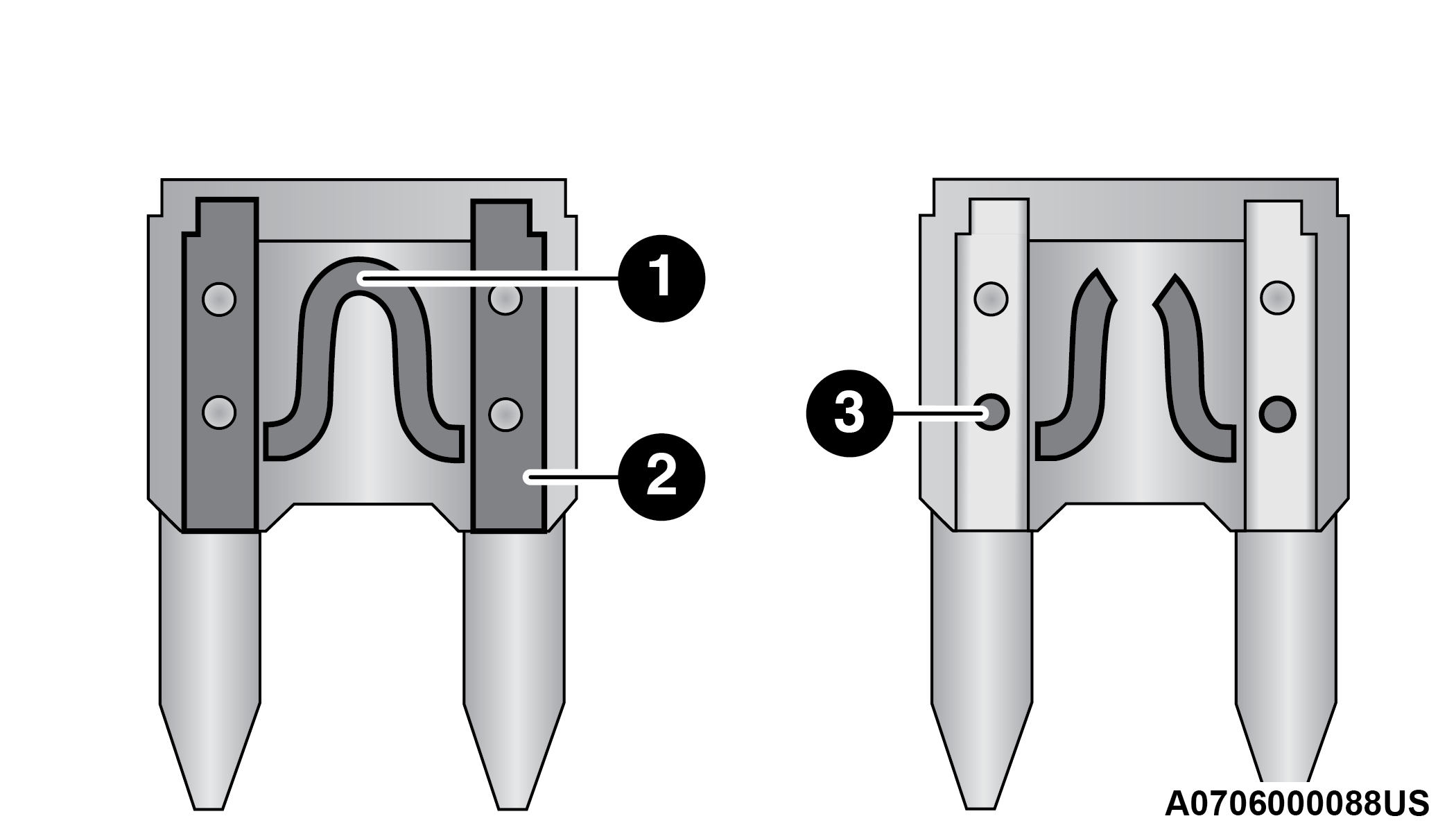
Blade Fuses
| 1 — Fuse Element |
| 2 — Blade Fuse with a good/functional fuse element |
| 3 — Blade fuse with a bad/not functional fuse element (blown fuse) |
ACCESS TO THE FUSES
The fuses are grouped into four controllers located in the engine compartment, under the instrument panel and on the inside of the left side cargo trim panel.
ENGINE COMPARTMENT FUSES/DISTRIBUTION UNIT
The engine compartment fuse panel is located on the left side of the engine compartment.
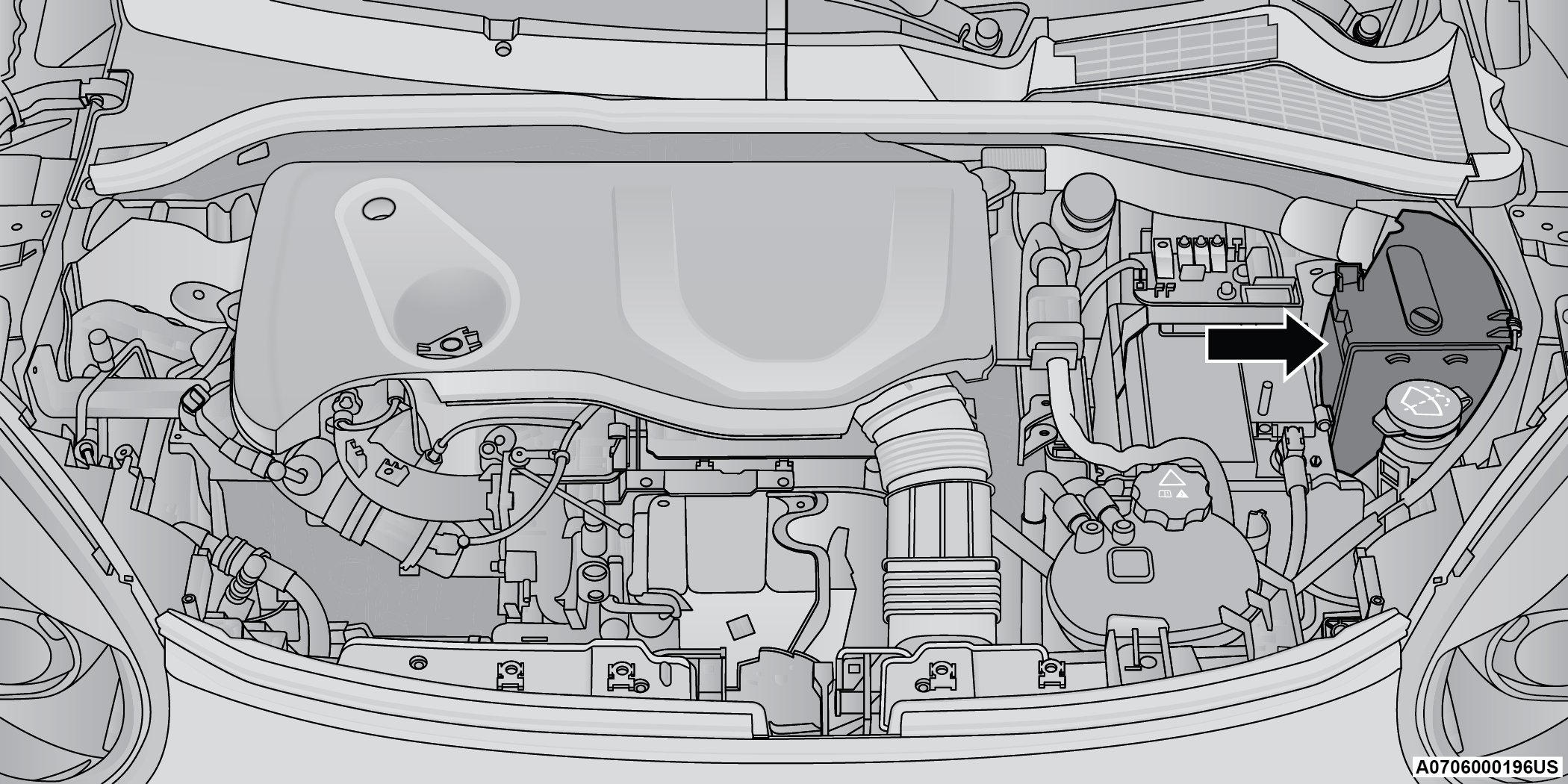
Engine Compartment Fuse Location
Removing Fuse Cover and Locking Screw
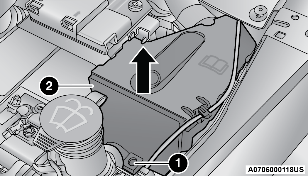
Fuse Panel & Cover Location
|
1 — Mounting Screw |
|
2 — Fuse Cover |
Proceed as follows:
Slowly turn the screw counterclockwise.
Slowly release the screw.
Remove the fuse cover by sliding it upward.
Mounting Fuse Cover and Locking Screw
Proceed as follows:
Properly secure the fuse cover to the box, slide completely from top to bottom.
Fully press the screw, using the special screwdriver supplied.
Slowly turn the screw clockwise.
Release the screw.
|
Cavity |
Maxi Fuse |
Cartridge Fuse |
Micro Fuse |
Description |
|
* If Equipped |
||||
|
F01 |
70 Amp Tan |
– |
– |
Module Body Computer |
|
F02 |
70 Amp Tan |
– |
– |
Module Body Computer, Rear Distribution Unit |
|
F03 |
– |
20 Amp Blue |
– |
Controller Power Supply Body Computer |
|
F04 |
– |
30 Amp Pink |
– |
Brake Control Electronics Module |
|
F05 |
70 Amp Tan |
– |
– |
Electric Power-Assisted Steering |
|
F06 |
70 Amp Tan |
– |
– |
Engine Cooling Fan |
|
F08 |
– |
30 Amp Pink |
– |
Automatic Transmission, GSM |
|
F09 |
– |
– |
5 Amp Tan |
Control Module Engine |
|
F10 |
– |
– |
15 Amp Blue |
Horn |
|
F11 |
– |
– |
5 Amp Tan |
Supply Secondary Loads |
|
F14 |
– |
– |
15 Amp Blue |
WCAC Pump/Active Grille Shutters |
|
F15 |
40 Amp Orange |
– |
– |
Brake Control Module Pump |
|
F16 |
– |
– |
5 Amp Tan |
Engine Control Module Power, Automatic Transmission |
|
F17 |
– |
– |
30 Amp Green |
Supply Primary Loads |
|
F18 |
– |
– |
5 Amp Tan |
Intelligent Battery Sensor |
|
F19 |
– |
– |
7.5 Amp Brown |
Air Conditioner 1.3L Compressor |
|
F20 |
– |
– |
5 Amp Tan |
Electronic Power Four-Wheel Drive |
|
F21 |
– |
– |
15 Amp Blue |
Fuel Pump |
|
F22 |
– |
– |
10 Amp Red |
Power Control Module Engine |
|
F23 |
– |
– |
30 Amp Green |
Heated Windshield * |
|
F24 |
– |
– |
15 Amp Blue |
Electronic Unit Supply Automatic Transmission |
|
F82 |
– |
20 Amp Yellow |
– |
Power Control Module Engine |
|
F83 |
– |
40 Amp Green |
– |
Air Conditioning Fan |
|
F84 |
– |
– |
30 Amp Green |
Power Supply All Wheel Drive |
|
F87 |
– |
– |
5 Amp Tan |
Gear Selector Automatic Transmission |
|
F88 |
– |
– |
7.5 Amp Brown |
Heated Outside Mirrors |
|
F89 |
– |
30 Amp Green |
– |
Heated Rear Window |
BODY COMPUTER FUSE CENTER
The controller is located at the left side of the steering column at the bottom of the instrument panel.
For the fuse replacement see an authorized dealer.
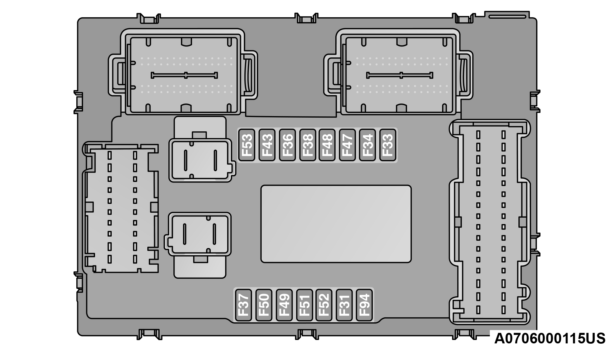
Body Controller Fuse Cavities
|
Cavity |
Mini Fuse |
Description |
|
F31 |
7.5 Amp Brown |
Flashes/Electrical Movement Front Seats/Fan Air Conditioning |
|
F33 |
20 Amp Yellow |
Power Window Front (Passenger Side) |
|
F34 |
20 Amp Yellow |
Power Window Front (Driver Side) |
|
F36 |
15 Amp Blue |
Supply Uconnect System, Air Conditioning, USB Port, Rear Ceiling Lights (With Sunroof), E-Call, SGW |
|
F37 |
10 Amp Red |
System Power Forward Collision Warning Plus, All Wheel Drive (AWD), IPC, Brake Pedal Switch (NC) |
|
F38 |
20 Amp Yellow |
Central Locking |
|
F42 |
7.5 Amp Brown |
Power Under Lock and Key, Brake Control Electronics Module, Electric Power-Assisted Steering |
|
F43 |
20 Amp Yellow |
Bi-directional Pump Washer |
|
F47 |
20 Amp Yellow |
Power Rear Window (Driver Side) |
|
F48 |
20 Amp Yellow |
Power Rear Window (Passenger Side) |
|
F49 |
7.5 Amp Brown |
Supply ParkSense, SGW, Mirror, Heated Front Seats, Stabilizer Battery, ESC System, S&S Inhibition Command, Blind Spot, Rain/Light Sensor, Humidity Sensor |
|
F50 |
7.5 Amp Brown |
Supply Air Bag |
|
F51 |
7.5 Amp Brown |
Air Conditioning, Lane Departure Warning, Terrain Selector, Trailer Tow Module, Compass Module, Rear View Camera |
|
F53 |
7.5 Amp Brown |
Supply IPC/Starter Device/System Keyless Enter ‘n Go™ |
|
F94 |
15 Amp Blue |
Power Socket |
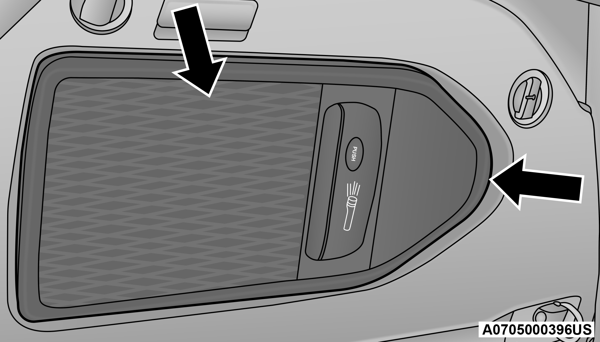
REAR CARGO FUSE/RELAY DISTRIBUTION UNIT
To access the fuses, remove the access door from the left rear panel of the rear cargo area.
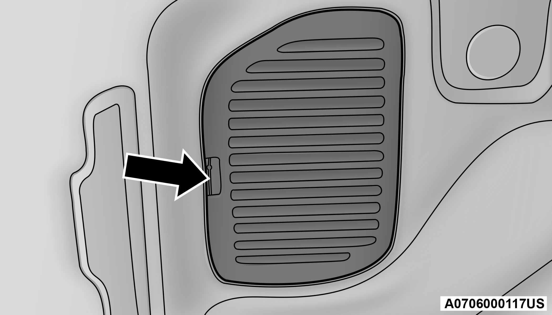
Rear Fuse Access Door
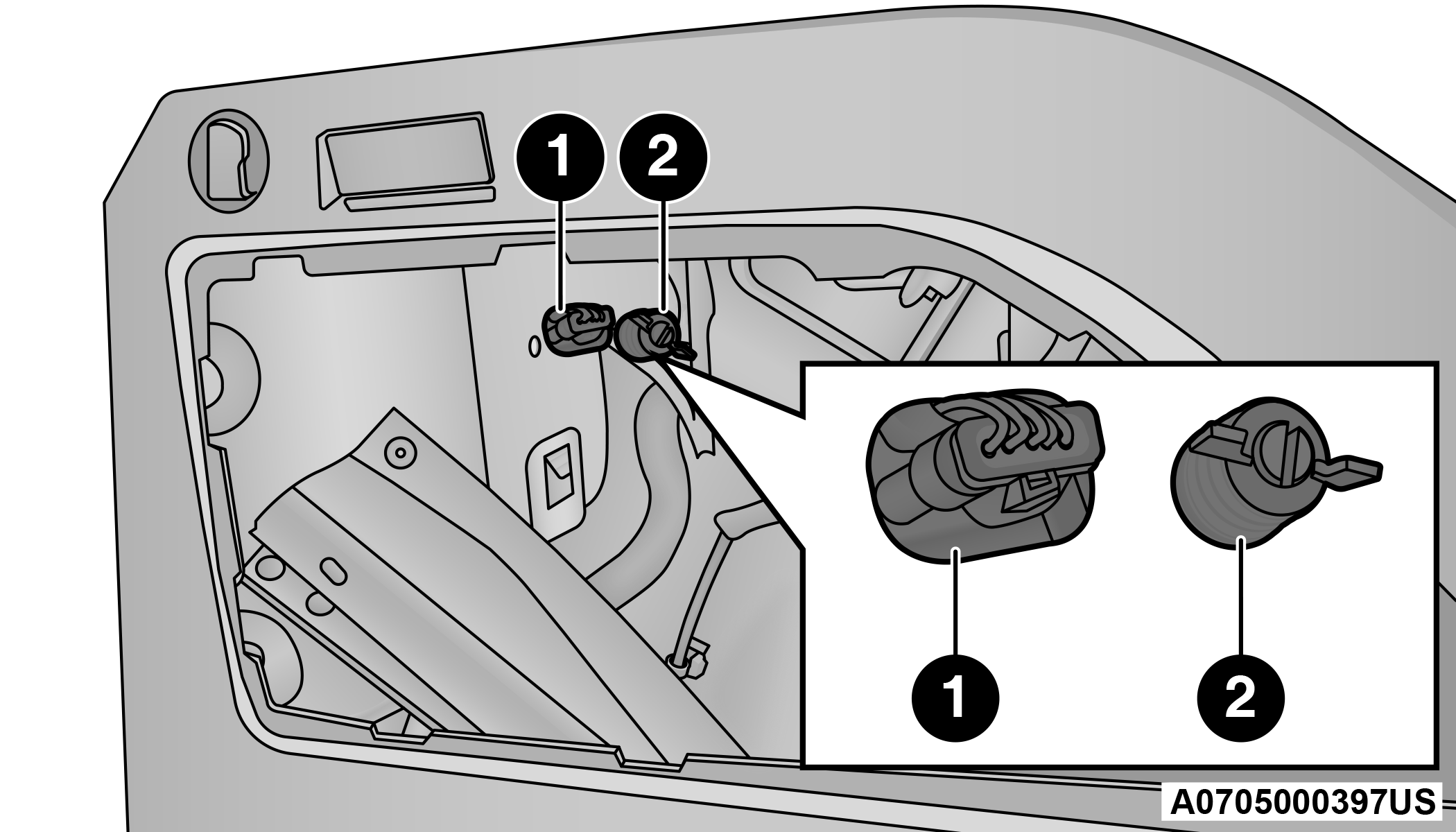
The fuses may be contained in two units. Fuse holder No. 1 and fuse holder No. 2 (if equipped with trailer towing) are located closest to the rear of the vehicle.
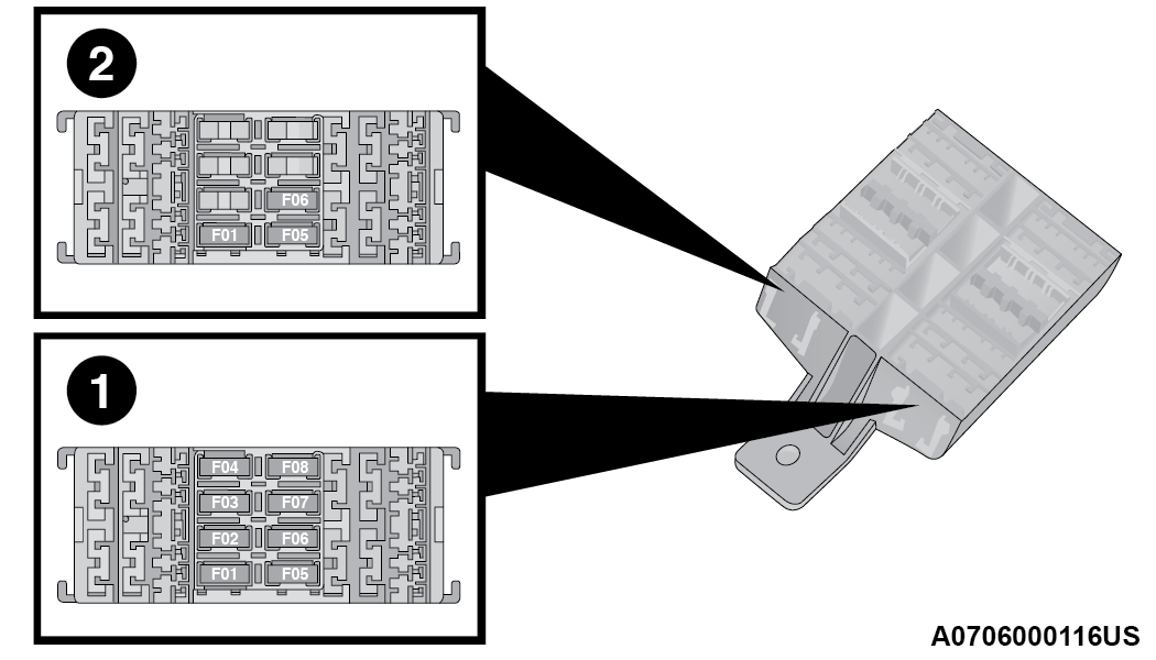
Rear Cargo Fuse Cavities
|
1 — Fuse Holder No. 1 |
|
2 — Fuse Holder No. 2 |
Fuse Holder No. 1
|
Cavity |
Mini Fuse |
Description |
|
F1 |
30 Amp Blue |
Power Inverter |
|
F2 |
20 Amp Yellow |
HIFI Audio System |
|
F3 |
20 Amp Yellow |
MY SKY |
|
F5 |
30 Amp Green |
Power Seat (Driver Side) |
|
F6 |
7.5 Amp Brown |
Lumbar Adjustment Front Seat (Driver Side) |
|
F8 |
20 Amp Yellow |
Heating Front Seats |
Fuse Holder No. 2
|
Cavity |
Mini Fuse |
Description |
|
F5 |
15 Amp Blue |
Controller Exterior Lighting Lights (Drivers Side) |
|
F6 |
15 Amp Blue |
Controller Exterior Lighting Lights (Passenger Side) |
On the controller there is also a 20 amp fuse for the sun visor of the retractable roof.
BULB REPLACEMENT
GENERAL INFORMATION
Before you replace a bulb, check the contacts to be sure they are not oxidized.
Replace the bulbs with the same type and wattage.
After replacing a light bulb, always check the correct orientation.
Before replacing a bulb that is not functioning, check that the fuse is intact.
Note:
Lens fogging can occur under certain atmospheric conditions. This will usually clear as atmospheric conditions change to allow the condensation to change back into a vapor. Turning the lamps on will usually accelerate the clearing process.
REPLACEMENT BULBS, NAMES, AND PART NUMBERS
In the instance a bulb needs to be replaced, this section includes bulb description and replacement part numbers.
Note:
See an authorized dealer for LED bulb replacement.
|
Interior Bulbs |
|
|
Lamps |
Bulb Number |
|
Front Courtesy Light |
C5W |
|
Front Courtesy Lights (Sun Visors) |
C5W |
|
Rear Dome Light (Models Without Retractable Roof) |
C5W |
|
Rear Interior Lights (Models With Retractable Roof) |
C5W |
|
Interior Lights |
W5W |
|
Dome Light (Glove Compartment) |
W5W |
|
Exterior Bulbs |
|
|
Lamps |
Bulb Number |
|
Low Beam/High Beam Headlamps (LED Version) |
LED |
|
Low Beam/High Beam Headlamps |
H13 |
|
Front Position/Daytime Running Lights (DRL)/Front Turn Indicator |
PSY24W |
|
Front Direction Indicator Lamps (If Equipped With LED Headlamps) |
PSY24W |
|
Front Fog Lamps |
H11 |
|
Front Fog Lamps (LED Versions) |
LED |
|
Side Indicators (Front And Side View Mirror) |
WY5W |
|
Tail/Brake Lights/Turn Indicators (LED Versions) |
LED |
|
Tail/Brake Lights/Turn Indicators |
P21W |
|
Center High Mounted Stop Lamp (CHMSL) |
LED |
|
Reverse |
W16W |
|
License Plate Lamp |
W5W |
REPLACING EXTERIOR BULBS
CAUTION:
During bulb replacement do not touch the new glass bulb with your fingers. Oil contamination will severely shorten bulb life. If the bulb comes in contact with any oily surface, clean the bulb with rubbing alcohol.
Headlamps
Hi/Lo Beam Light Halogen
See the following steps to replace:
-
Open the engine compartment and remove the headlamp bulb cap.
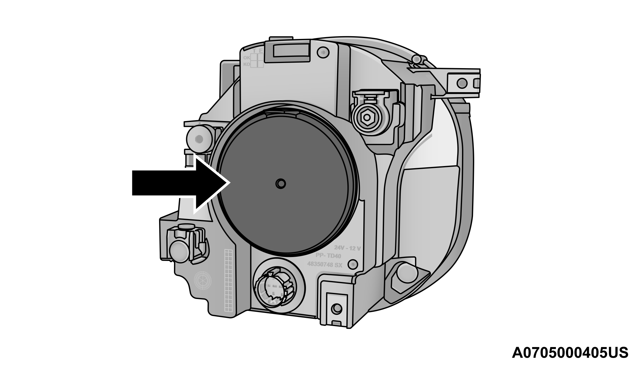
Headlamp Bulb Cap
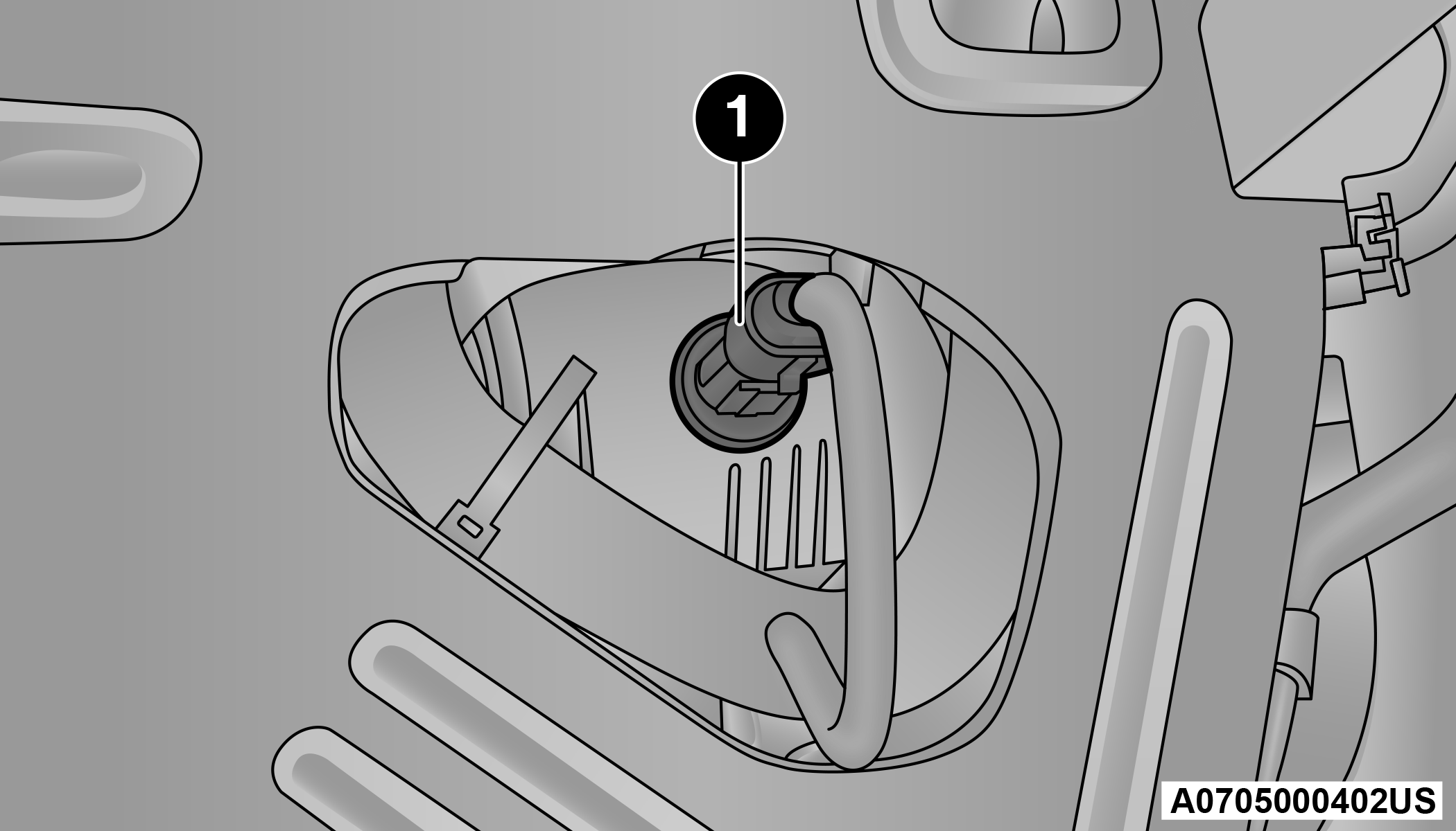
-
Rotate the headlamp bulb socket counterclockwise then pull outwards.
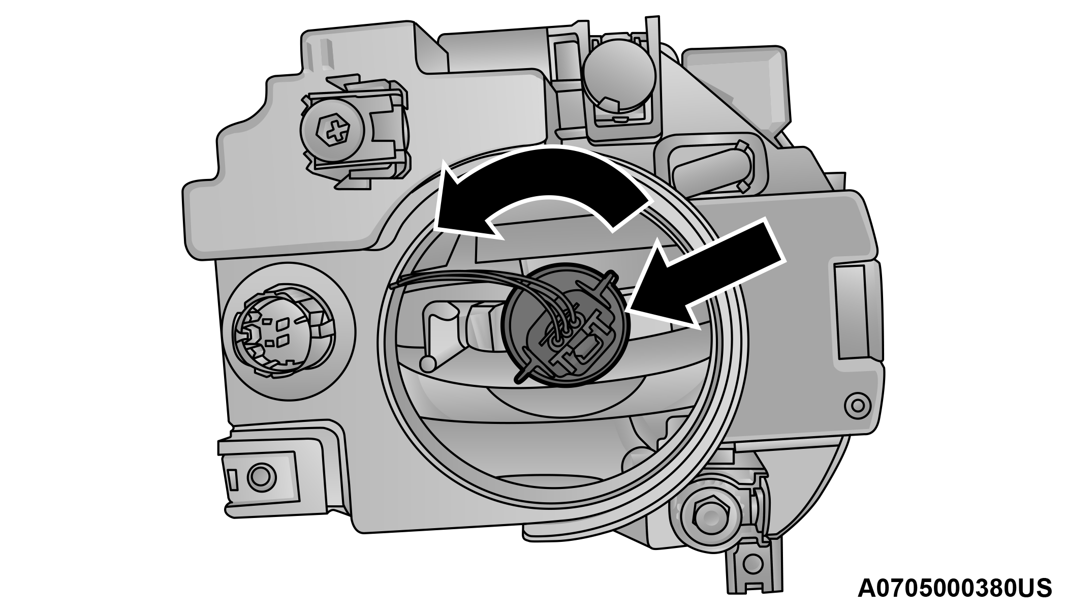
Headlamp Bulb Socket
-
Push on the locking tab on the headlamp bulb connector and remove the bulb and socket.
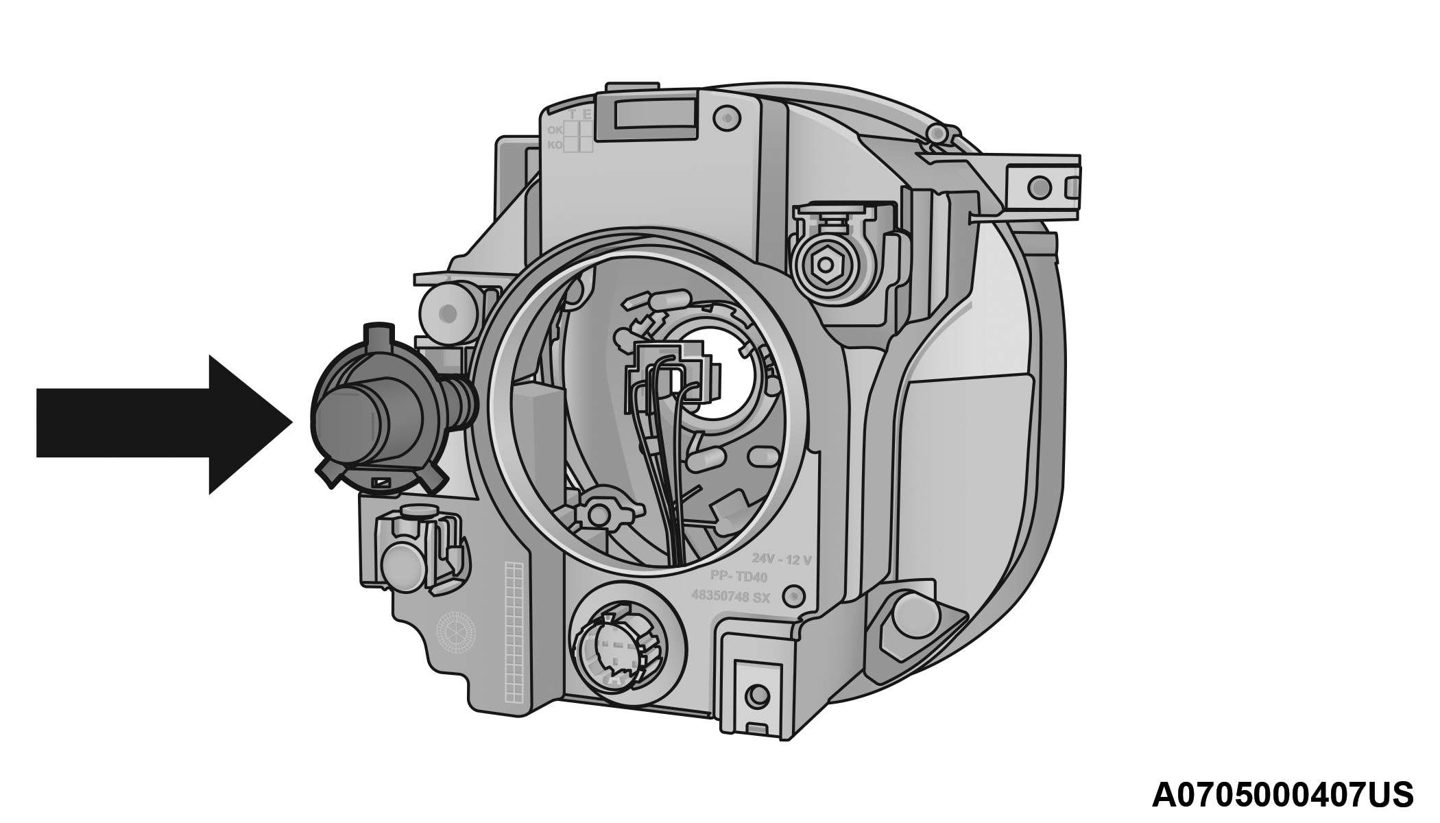
Headlamp Bulb
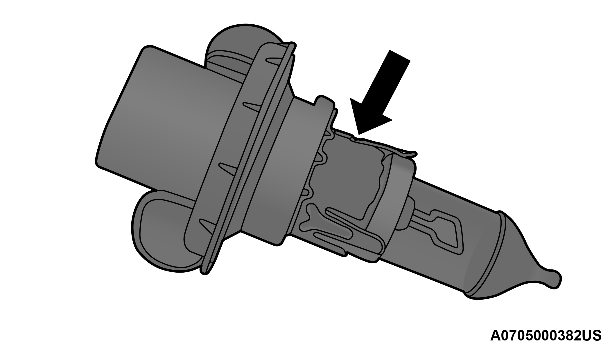
Headlamp Bulb
-
Install the new headlamp bulb making sure it is properly locked.
-
Install the headlamp bulb and socket; turn it clockwise making sure it is properly locked.
WARNING:
Carry out the operation of replacing lamps only with the engine off. Also make sure that the engine is cold, to avoid the danger of burns.
LED Headlamps – If Equipped
For replacement see an authorized dealer.
Position Lights/Daytime Running Lights/Fog Lights
See the following steps to replace:
-
Turn the front wheels completely.
-
Use a suitable tool to remove the access door.
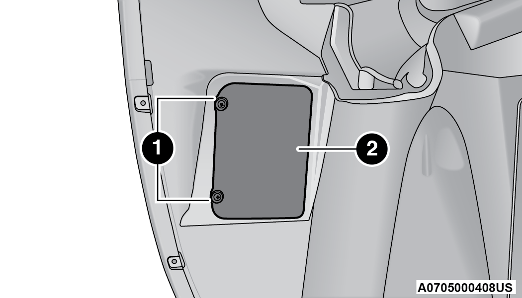
Position Light/Daytime Running Light/Fog Light Access
1 — Screws 2 — Access Door -
Remove the electrical connector.
-
Releasing the two tabs, and remove the bulb and bulb socket from the housing.
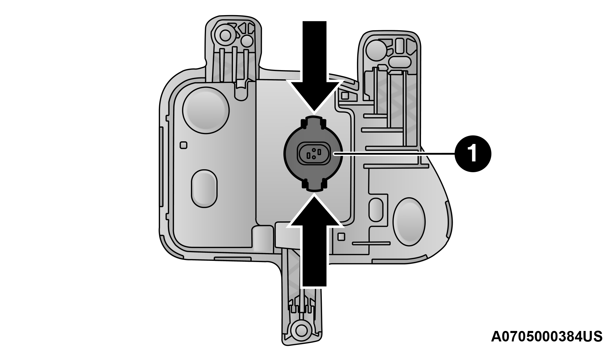
Position Light/Daytime Running Light Assembly
1 — Bulb Socket -
Install the new bulb and socket into the housing, and engage the two tabs, making sure that it is properly locked.
-
Reconnect the electrical connector.
-
Reinstall the access door.
Front Fog Lights
See the following steps to replace:
-
Turn the front wheels completely.
-
Use a suitable tool to remove the access door.
Position Light/Daytime Running Light/Fog Light Access
1 — Screws 2 — Access Door -
By pushing the electrical connector tab remove the electrical connector.
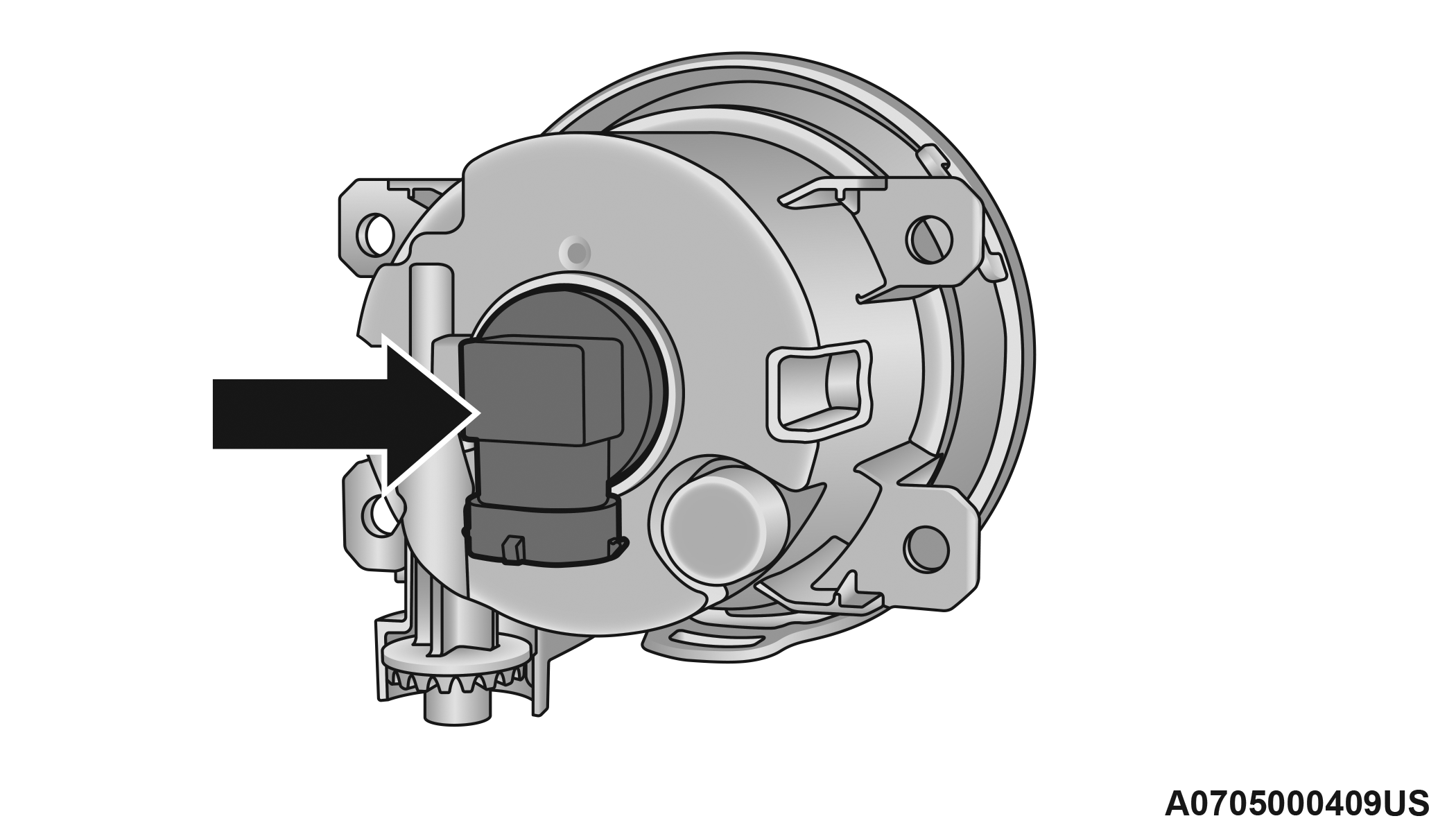
Fog Light Assembly
-
Rotate the bulb counterclockwise, and then replace the bulb.
-
Insert the new bulb in the socket, making sure the bulb is locked into place.
-
Reconnect the electrical connector.
-
Reinstall the access door.
LED Front Fog Lamps – If Equipped
For replacement see an authorized dealer.
Front Side Indicators
See the following steps to replace:
-
Operating from inside the engine compartment using a suitable tool release the retaining clip.
-
Remove lamp assembly by sliding it toward the outside.
Lamp Assembly
-
Remove the electrical connector by pushing the tab then disconnect the electrical connector.
-
Rotate counterclockwise to release the bulb socket from the lamp assembly, and remove it.
Bulb Socket
-
Remove the bulb from the socket.
Bulb
-
Insert the new bulb in the socket.
-
Reinstall the bulb and socket into the lamp assembly by turning it clockwise, making sure it is locked into place.
-
Reconnect the electrical connector.
-
Reinstall the lamp assembly on the car, making sure it is locked into place.
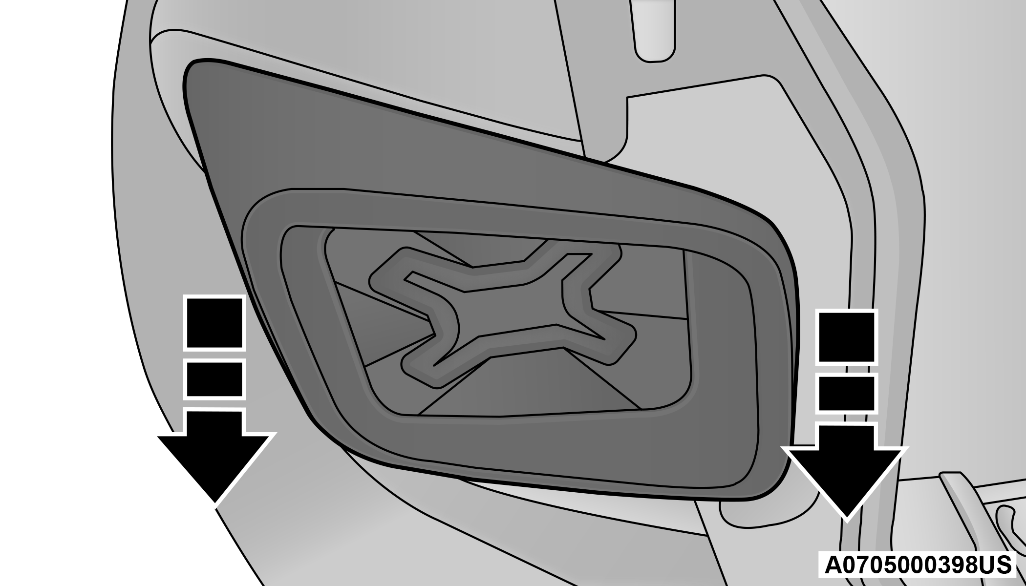
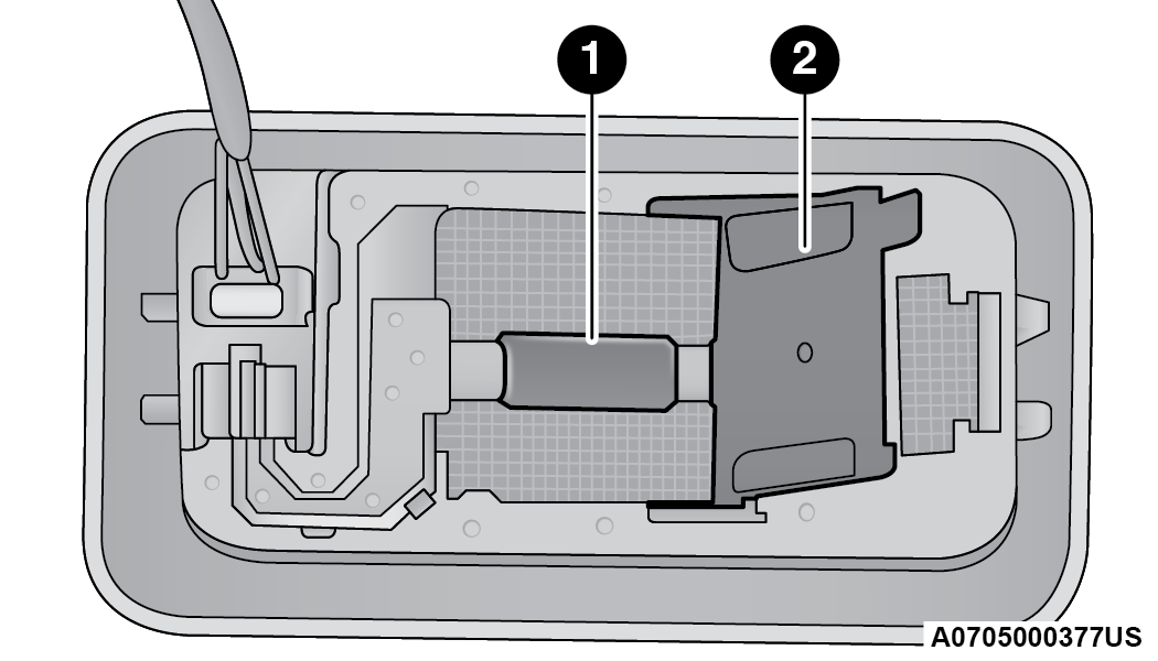
Side Indicators on External Rear View Mirrors – (If Equipped)
CAUTION:
The procedure is described as a guideline. For the replacement of the lamp it is recommended that you contact an authorized dealer.
See the following steps to replace:
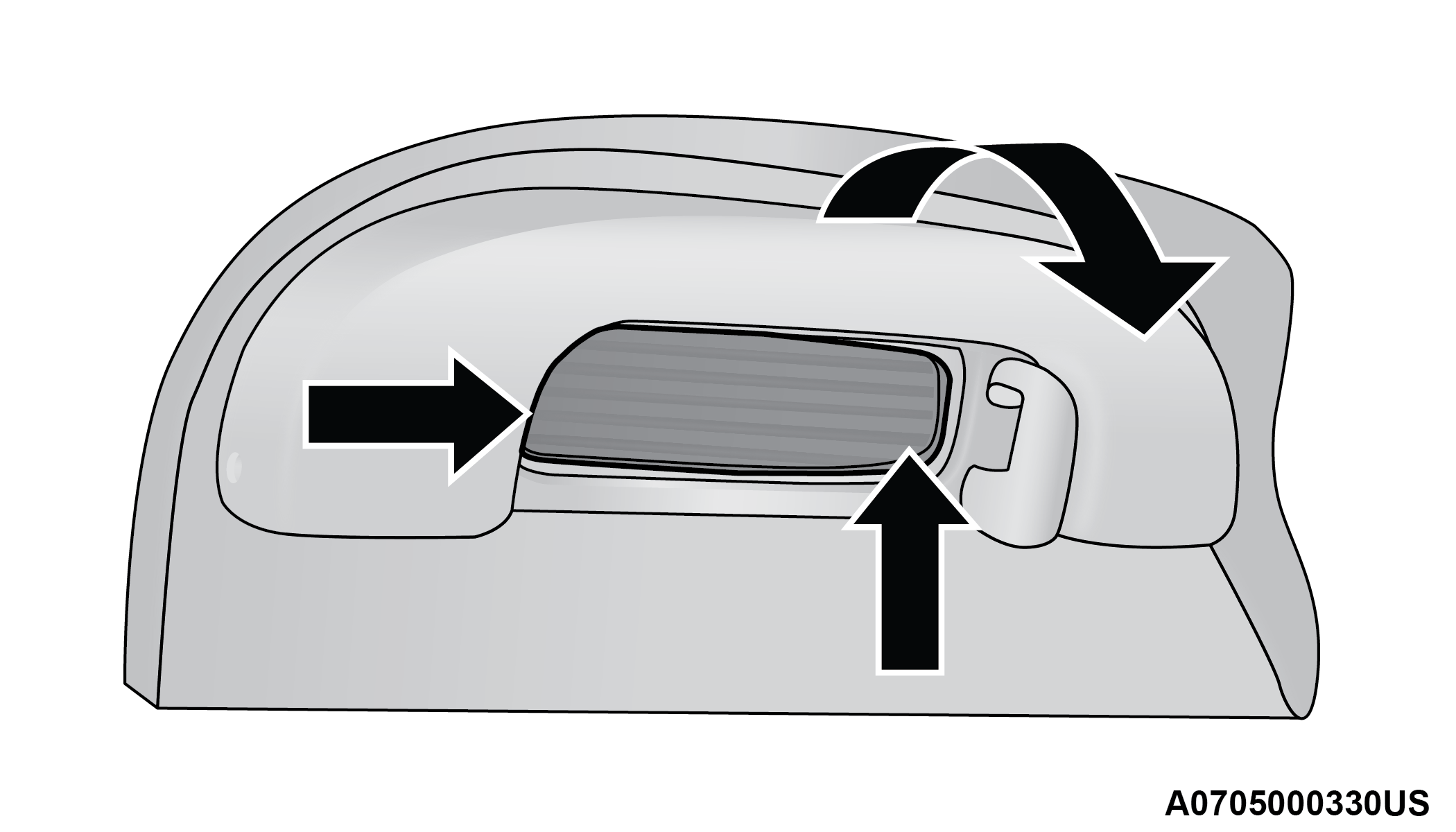
-
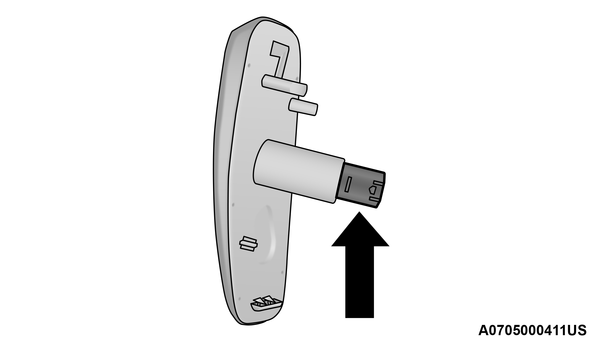
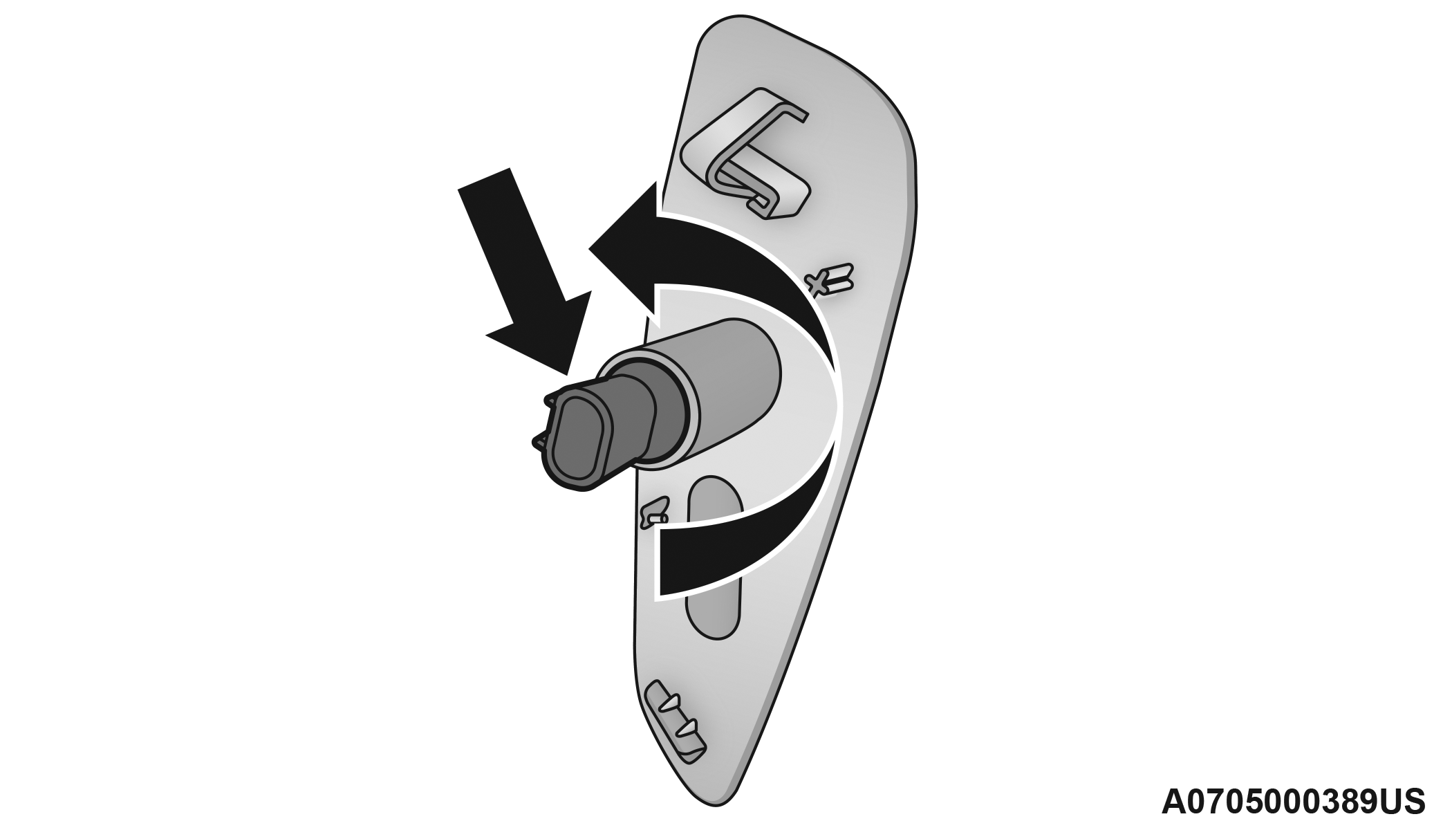
Remove the mirror cap on the outside rear view mirror.
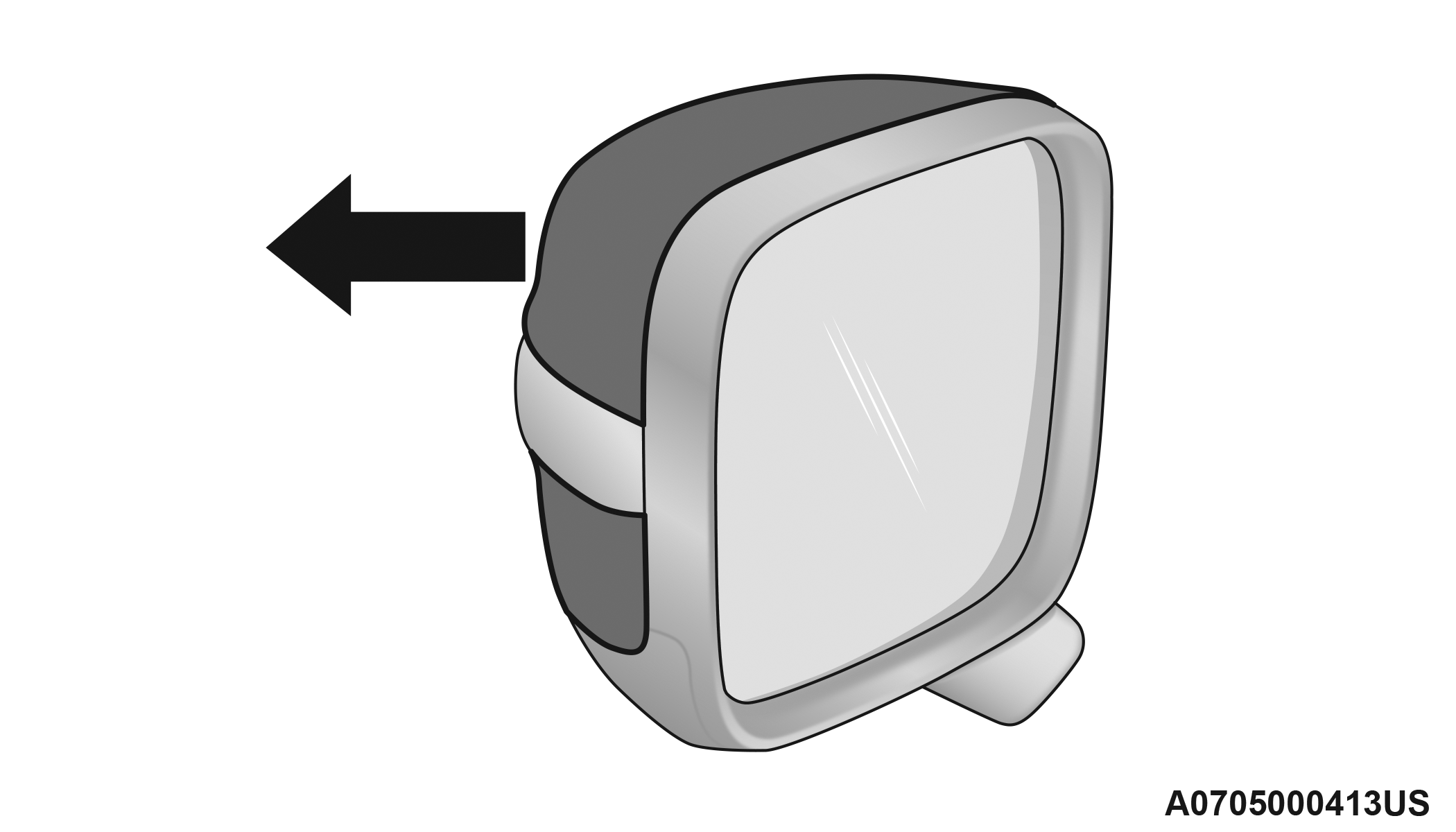
Removing The Mirror Cap
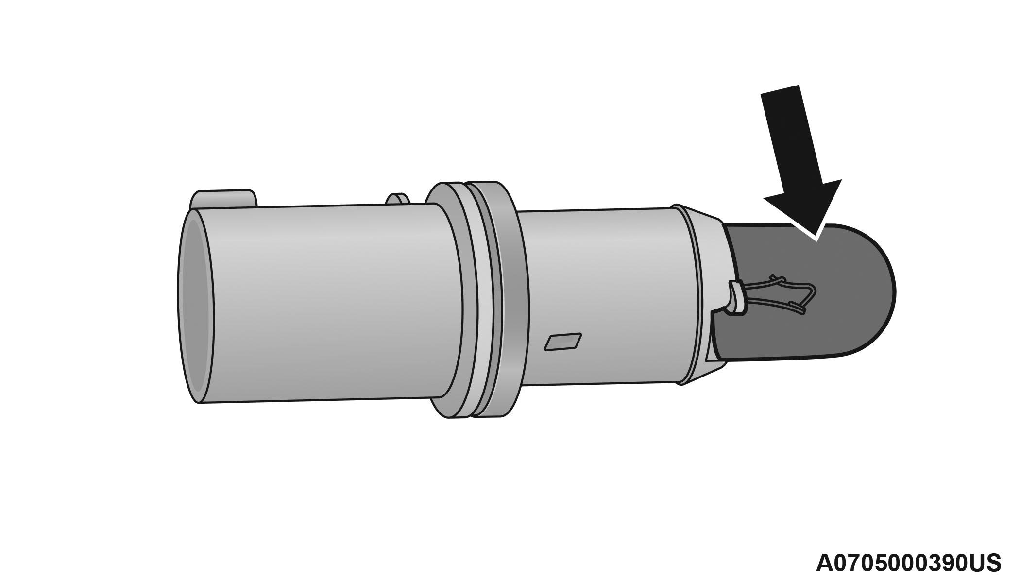
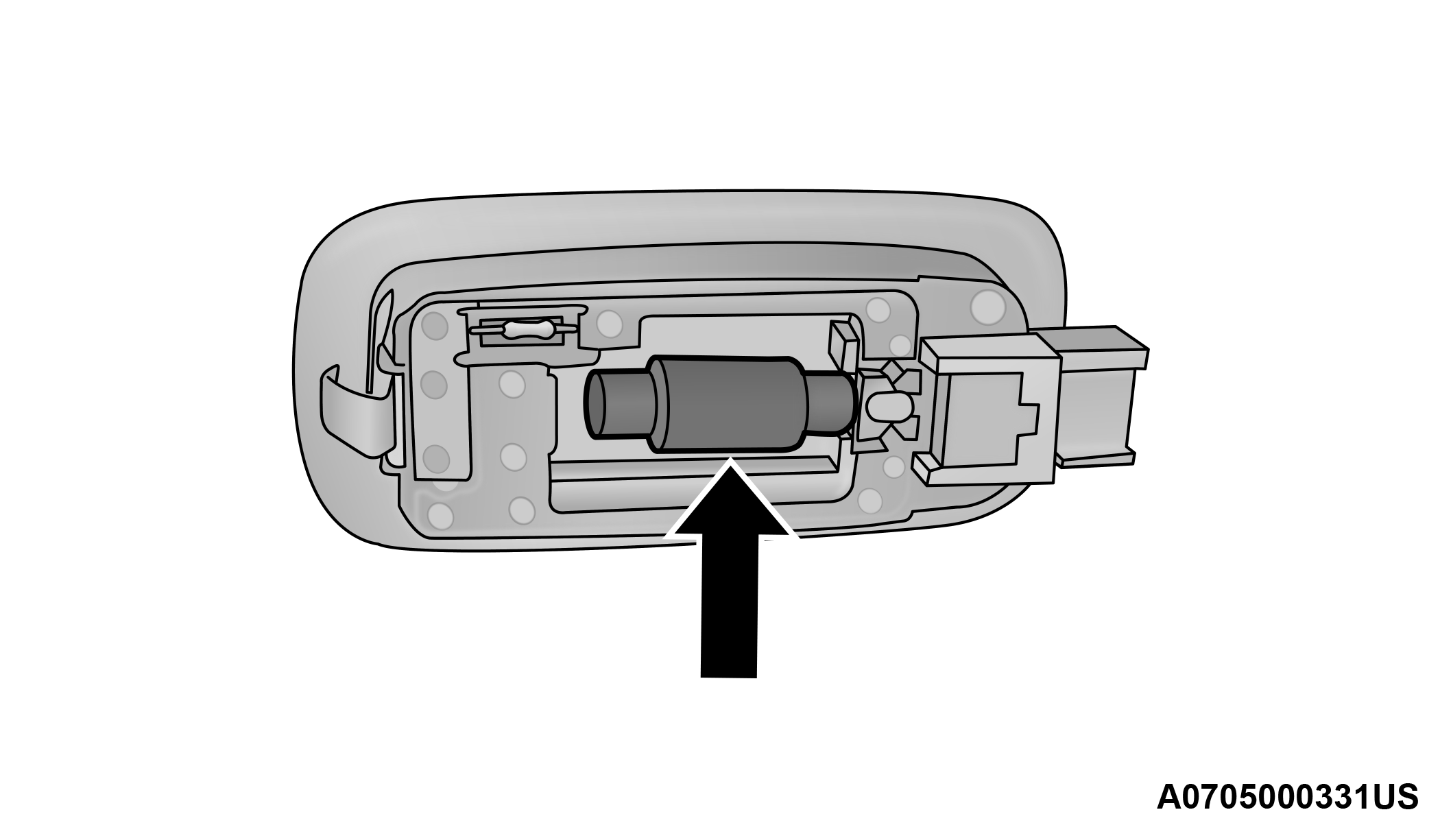
-
Remove the transparent lens assembly as shown.
Transparent Lens Location
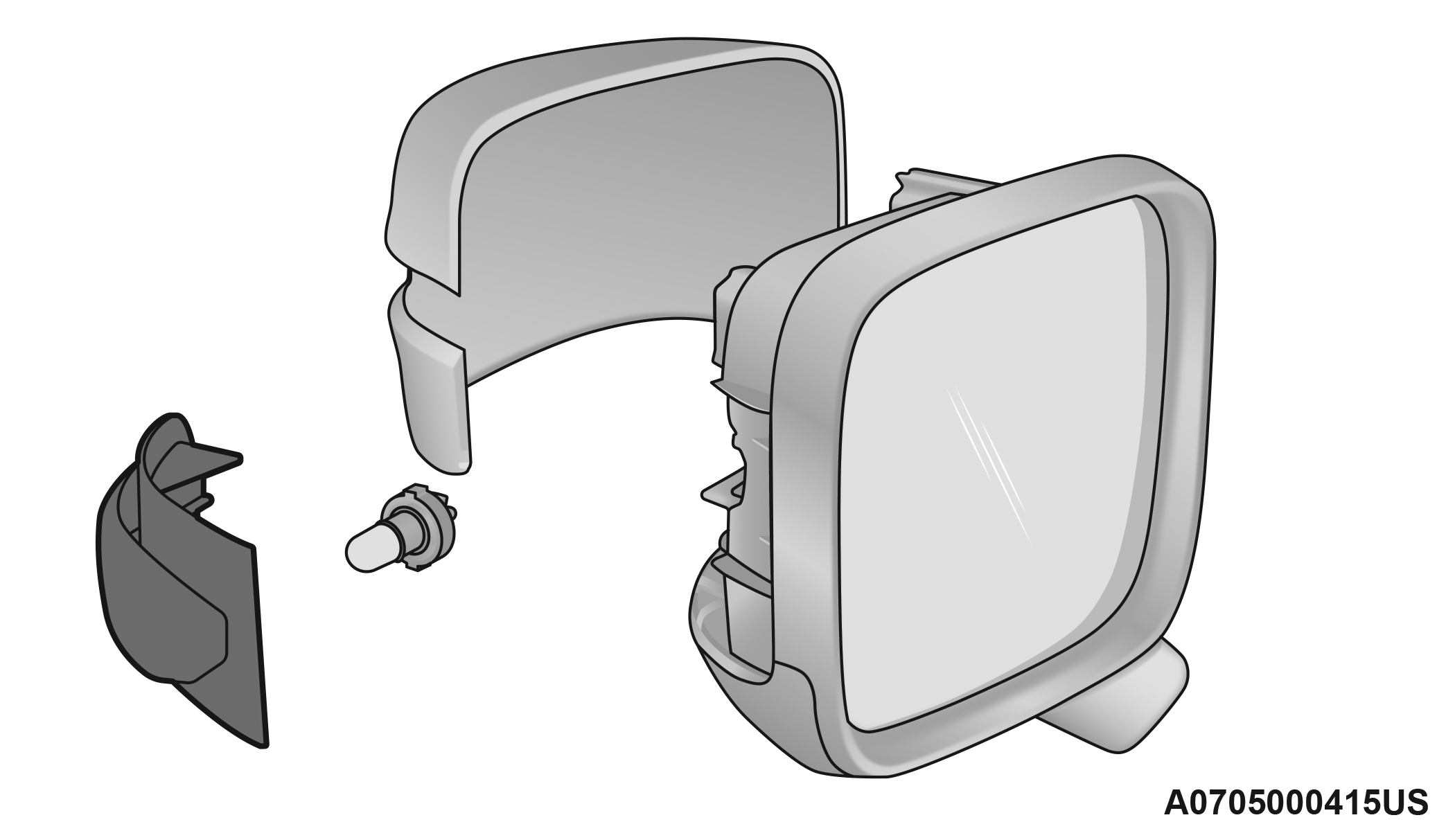
Transparent Lens Removed
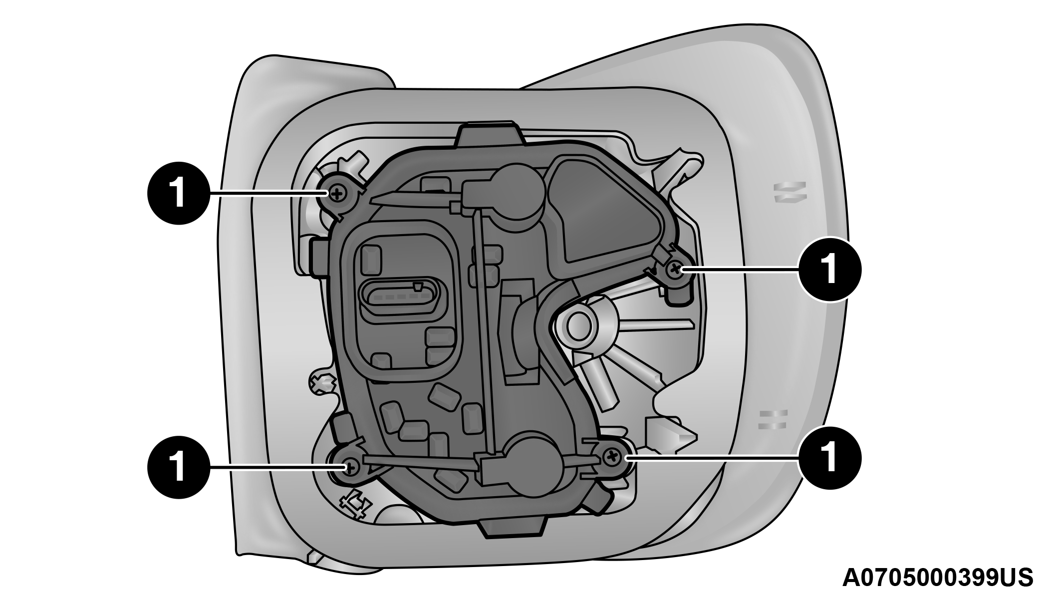
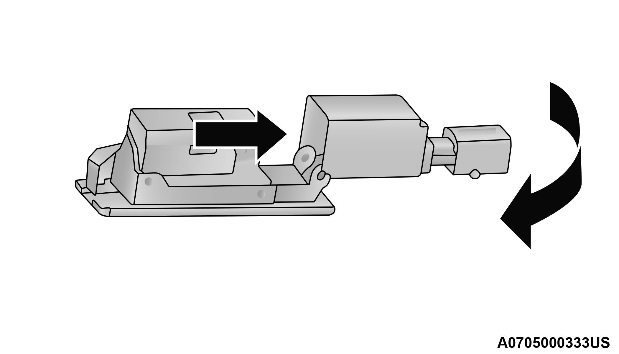
-
Remove the bulb socket and bulb from the transparent lens assembly by rotating the socket counterclockwise.
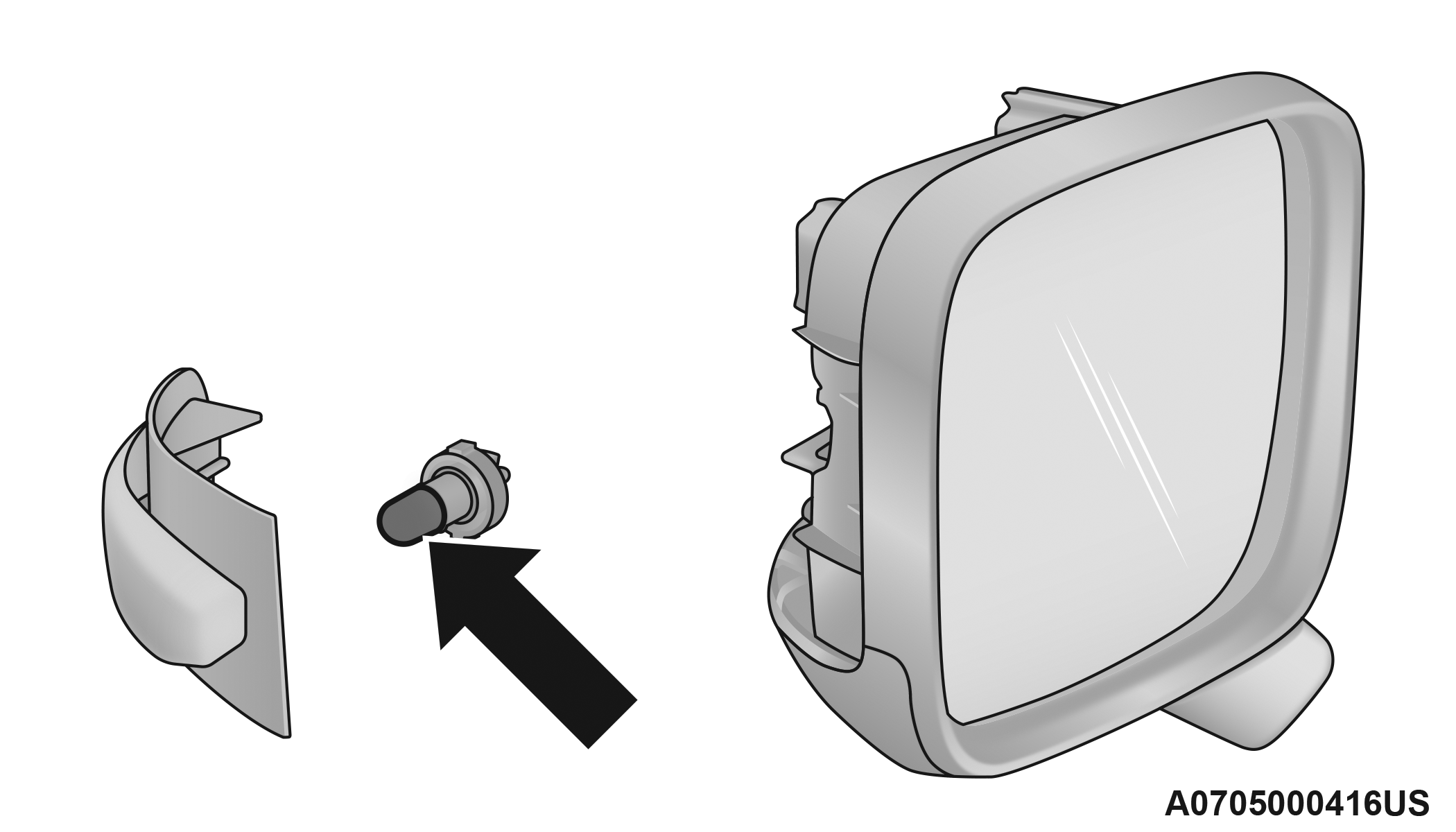
Bulb Removal
-
Remove the bulb from the bulb socket by pulling the bulb straight out.
-
Insert the new bulb, making sure that it is locked into place.
-
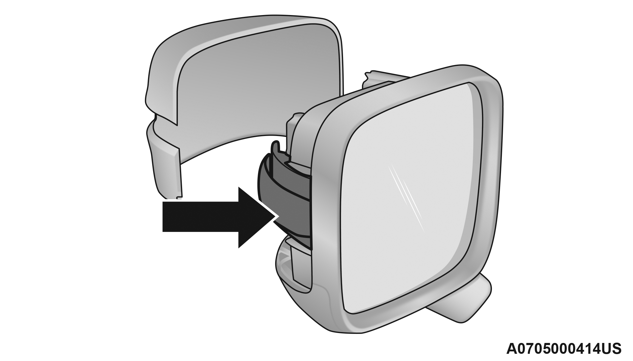
Reinstall the socket into the transparent lens assembly.
-
Reinstall the cover on the outside rear view mirror, making sure it is locked into place.
Rear Tail Lamps
Contain the following:
Position Lights
Stop Lights
Direction Indicator
REVERSE Lights
See the following steps to replace:
-
Open the liftgate.
-
Using a suitable tool remove the door as shown.
Trim Panel Door
-
Using a suitable tool remove fastener.
-
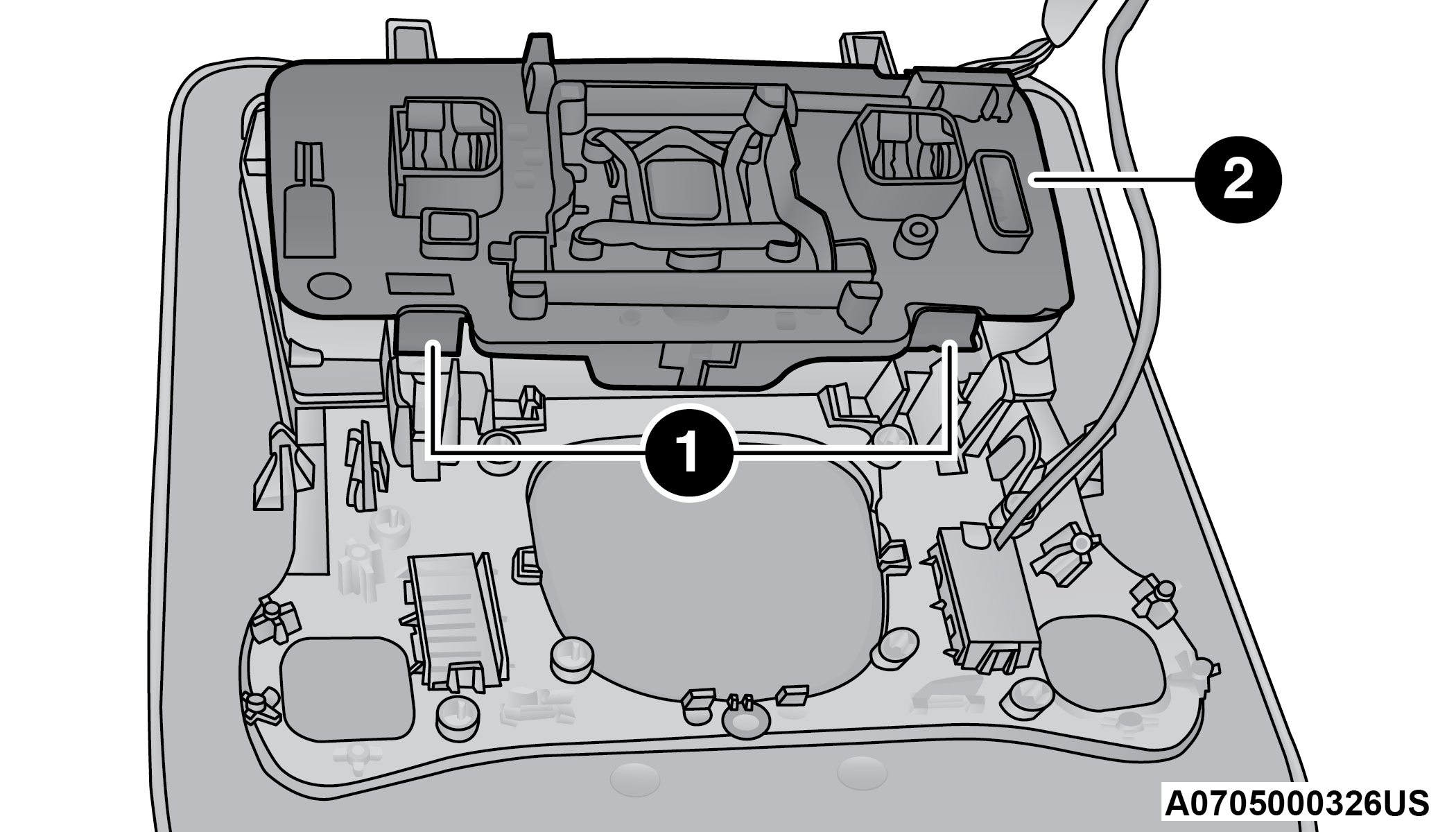
Disconnect the electrical connector by pushing the release.
Rear Lamp Fastener And Electrical Connector
1 — Electrical Connector 2 — Fastener -
Remove the rear tail lamp, sliding it toward the outside as shown.
Tail Lamp Removal
-
Unscrew the screws and remove the rear tail lamp holder.
Rear Lamp Assembly
1 — Mounting Screws -
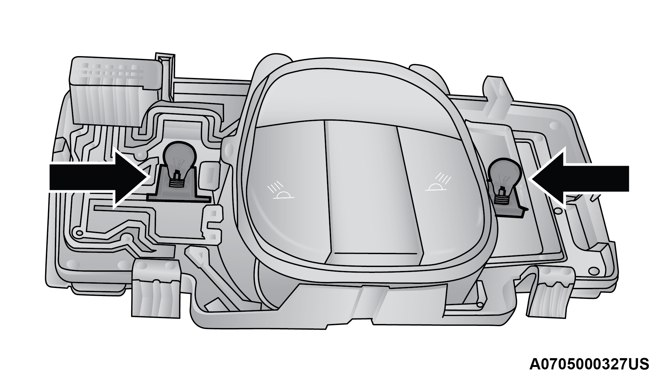
Replace the bulb as necessary.
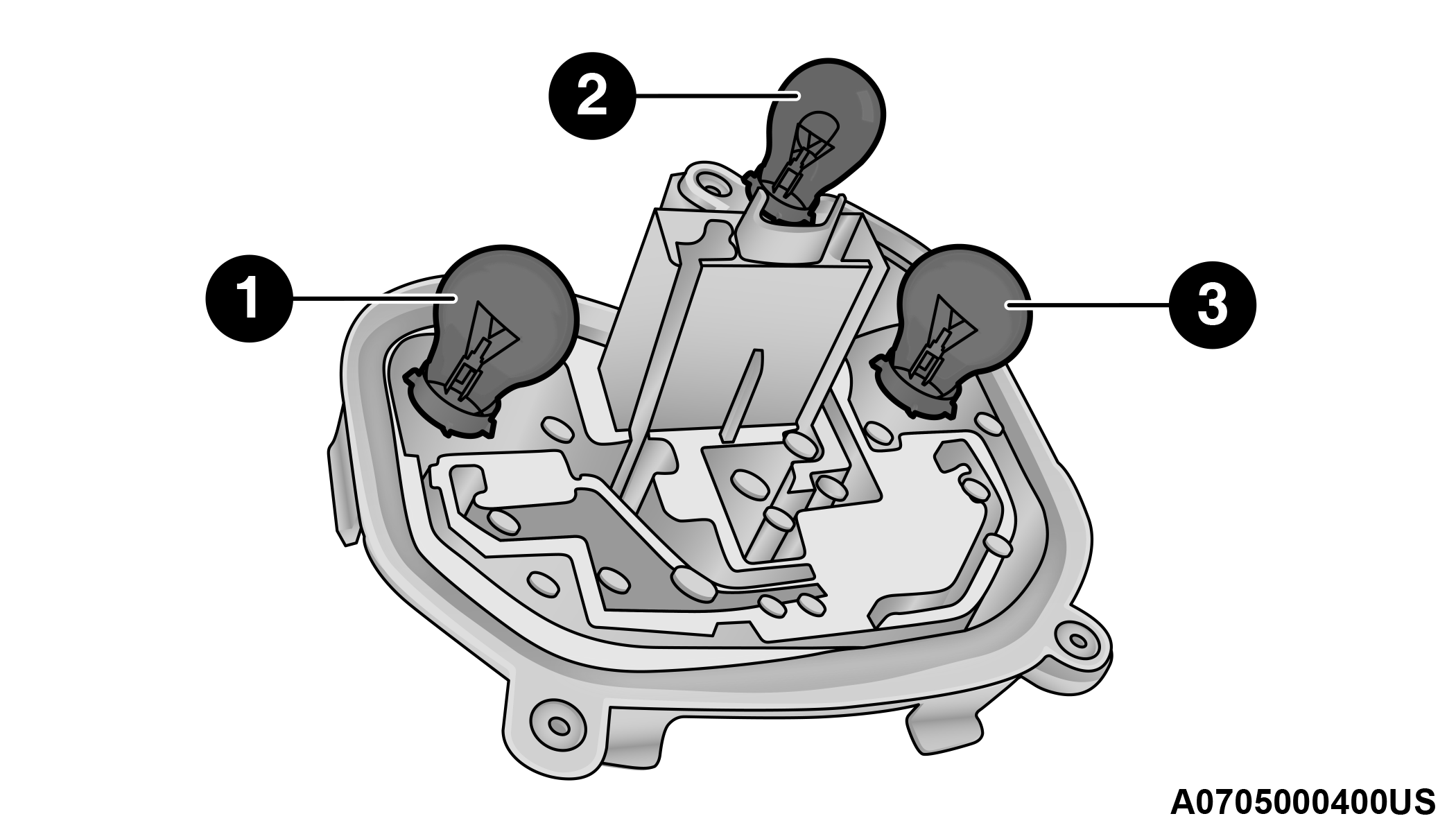
Rear Tail Lamp Holder
1 — Tail Light 2 — Reverse Bulb 3 — Position Light/Stop Light/Turn Signal -
Insert the new bulb, making sure it is properly locked.
-
Reassemble the lamp assembly on the rear tail lamp housing, tightening the screws.
-
Reposition the rear tail lamp on the car.
-
Secure the fastener of the rear tail lamp and reconnect the electrical connector.
-
Reinstall the door making sure it locked into place.
-
Finally close the liftgate.
LED Rear Tail Lamps – If Equipped
For replacement see an authorized dealer.
Reverse Lights – If Equipped With LED Tail Lamps
See the following steps to replace:
-
Use a suitable tool to remove the screws and remove the access door.
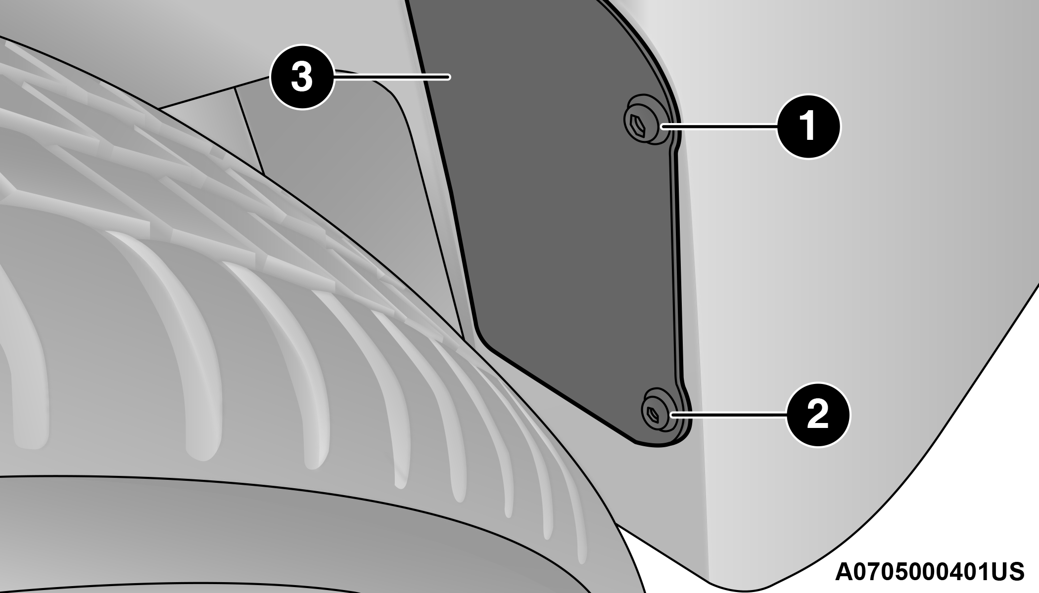
Reverse Light Access
1 — Screw 2 — Screw 3 — Access Door -
By pushing the electrical connector tab remove the electrical connector.
Reverse Light Assembly
1 — Bulb -
Rotate the bulb counterclockwise, and then replace the bulb.
-
Insert the new bulb in the socket, making sure the bulb is locked into place.
-
Reconnect the electrical connector.
-
Reinstall the access door.
Center High Mounted Stop Lamp (CHMSL)
The CHMSL is LED. For replacement see an authorized dealer.
License Plate Lights
See the following steps to replace:
-
Using a suitable tool remove the license plate lens.
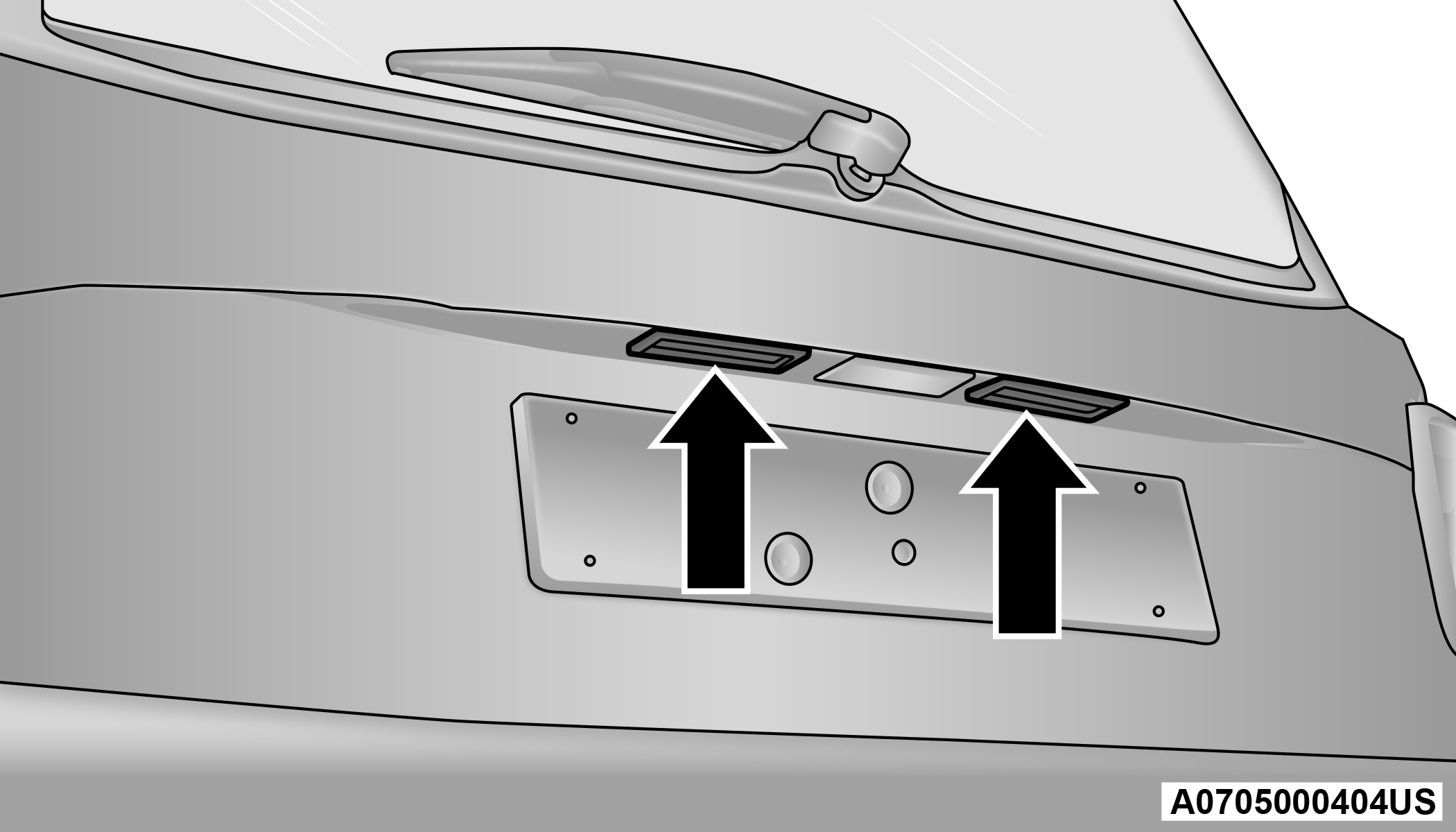
License Plate Light Location
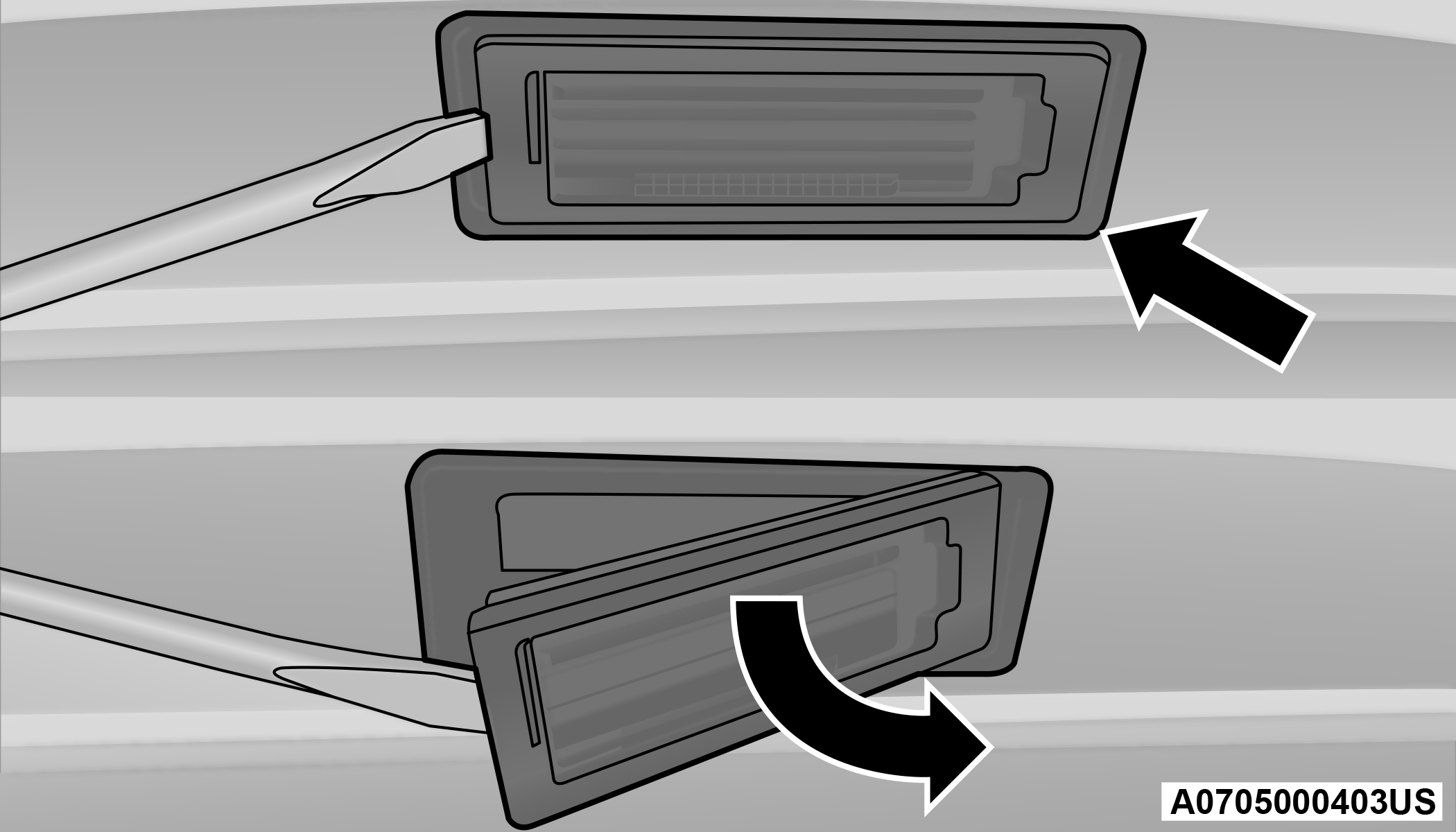
License Plate Light
-
Remove the bulbs from the individual side contacts.
-
Insert the new bulbs, and ensure that they are properly locked between the contacts.
-
Reinstall the license plate lens.
Note:
If removing the license plate lens using a screwdriver, be sure to cover the tip of the screwdriver with a cloth so no damage is done to the lenses or the vehicle paint.
REPLACING INTERIOR BULBS
Front Courtesy Light
See the following steps to replace:
-
Using a suitable tool remove the front courtesy light as shown.
Front Courtesy Light Housing
-
Release the retainer clips and bulb housing as shown.
Front Courtesy Bulb Housing
1 — Retaining Clips
2 — Bulb Housing
-
Replace the bulbs by pulling straight out of bulb housing.
Front Courtesy Bulb Housing
-
Insert the new bulbs, making sure that they are properly locked.
-
Reassemble the bulb housing and courtesy light housing making sure that they are properly locked.
-
Install the front courtesy light making sure that it is properly locked.
Dome Light Vanity Mirror
See the following steps to replace:
-
Lift the cover of the mirror and pull out the visor mirror light cover.
-
Replace the bulb, releasing it from the side contacts, and then insert the new bulb, making sure that it is properly locked between the contacts.
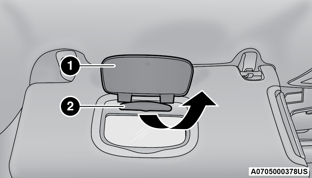
Visor
1 — Visor Mirror Cover
2 — Visor Mirror Light
-
Reinstall the visor mirror light cover making sure that it is properly locked.
-
Finally lower the visor mirror cover to the mirror.
Dome Light Glove Compartment
See the following steps to replace:
-
Open the glove compartment.
-
Place your fingers inside the light assembly, pull the bulb to replace it.
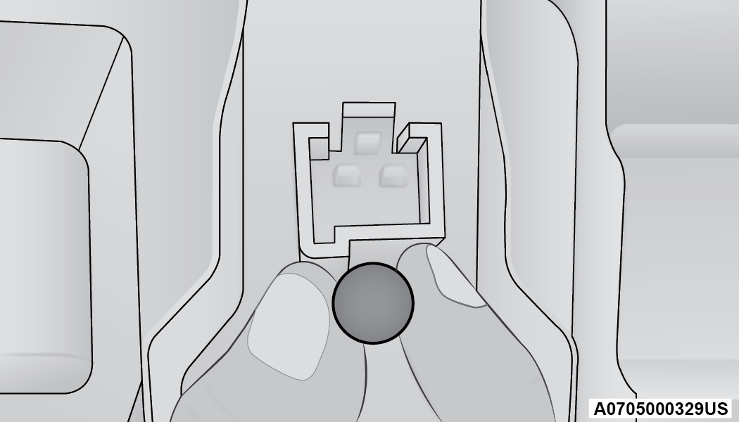
Bulb Removal/Installation
-
Insert the new bulb, making sure it is properly locked.
Rear Dome Light — Without Retractable Roof
See the following steps to replace:
-
Using a suitable tool release the lamp assembly at both the ends.
-
Open the flap and replace the bulb.
Rear Dome Light Housing
1 — Bulb
2 — Flap
-
Insert the new bulb, locking it between the contacts.
-
Reinstall the dome light.
Dome Light — MY SKY
See the following steps to replace:
-
Lower the handle in the direction shown remove the dome light.
Retractable Roof Light
-
Replace the bulb by removing it from the side contacts.
Bulb
-
Insert the new bulb, locking it between the contacts.
-
Reinstall the dome light.
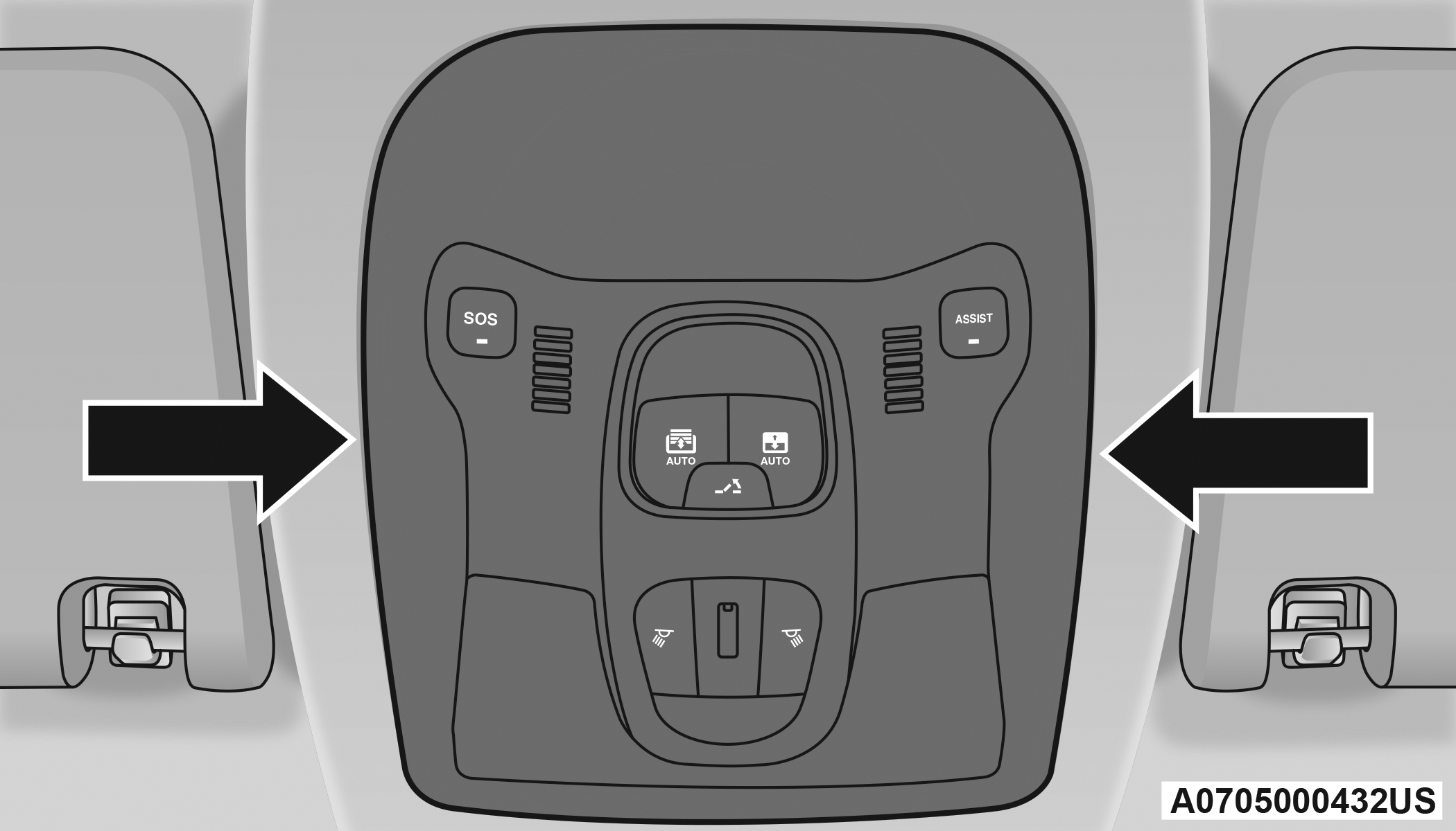
Interior Cargo Lights
See the following steps to replace:
-
Open the luggage compartment and remove the dome light assembly.
-
Open the light cover and replace the bulb.
Light Cover
-
Close the light cover over the bulb.
-
Reinstall the dome light in its correct position.
WARNING:
Before proceeding with the replacement of the lamp wait for the exhaust pipes are cool: DANGER OF BURNS!
Modifications or repair of the electrical system performed incorrectly and without taking into account the technical characteristics can cause malfunctions with the risk of fire.
Halogen lamps contain gas under pressure, in the event of breakage be careful of the projection of fragments of glass.
Halogen lamps must be handled by touching only the metallic part. If the transparent bulb is in contact with fingers, it reduces the intensity of the emitted light and it can also affect the life of the lamp. In case of accidental contact, rub the bulb with a cloth dampened with alcohol and allow to dry.
Download Manual