Do-it-yourself maintenance
|
Items |
Parts and tools |
|
Battery condition (P. 422) |
Warm water Baking soda Grease
Conventional wrench (for terminal clamp bolts)
|
|
Brake fluid level (P. 420) |
FMVSS No.116 DOT 3 or SAE J1703 brake fluid
Rag or paper towel
Funnel (used only for adding brake fluid)
|
|
Engine coolant level (P. 418) |
“Toyota Super Long Life Coolant” or a similar high quality ethylene glycol-based non-silicate, non- amine, non-nitrite and non-borate coolant with long- life hybrid organic acid technology
For the U.S.A.: “Toyota Super Long Life Coolant” is pre-mixed with 50% coolant and 50% deionized water. For Canada: “Toyota Super Long Life Coolant” is pre-mixed with 55% coolant and 45% deionized water. Funnel (used only for adding coolant)
|
|
Engine oil level (P. 416) |
“Toyota Genuine Motor Oil” or equivalent
Rag or paper towel
Funnel (used only for adding engine oil)
|
|
Fuses (P. 454) |
Fuse with same amperage rating as original
|
|
Light bulbs (P. 457) |
Bulb with same number and wattage rating as origi- nal
Phillips-head screwdriver
Flathead screwdriver Wrench
|
|
Power steering fluid level (P. 421) |
Automatic transmission fluid DEXRON® II or III
Rag or paper towel
Funnel (used only for adding power steering fluid)
|
|
Radiator and condenser (P. 420) |
- |
|
Tire inflation pressure (P. 442) |
Tire pressure gauge
Compressed air source
|
|
Washer fluid (P. 425) |
Water or washer fluid containing antifreeze (for win- ter use)
Funnel (used only for adding water or washer fluid)
|
WARNING
The engine compartment contains many mechanisms and fluids that may move suddenly, become hot, or become electrically energized. To avoid death or serious injury, observe the following precautions.
Be sure the engine switch is off.
With the engine switch in ON, the electric cooling fan may automatically start to run if the air conditioning is on and/or the coolant temperature is high. (P. 420)
Wear safety glasses to prevent flying or falling material, fluid spray, etc., from getting in your eyes.
The hood will pop up slightly.
Washer fluid tank (P. 425)
Engine oil level dipstick
(P. 416)
Engine coolant reservoir
(P. 418)
Engine oil filler cap (P. 417)
Brake fluid reservoir
(P. 420)
Fuse box (P. 454)
Battery (P. 422)
Radiator (P. 420) Cooling fan
Condenser (P. 420) Power steering fluid reservoir
(P. 421)
With the engine at operating temperature and turned off, check the oil level on the dipstick.
Park the vehicle on level ground. After warming up the engine and turning it off, wait more than 5 minutes for the oil to drain back into the bottom of the engine.
Holding a rag under the end, pull the dipstick out.
Wipe the dipstick clean. Reinsert the dipstick fully.
Holding a rag under the end, pull the dipstick out and check the oil level.
Low Normal Excessive
The shape of the dipstick may differ depending on the type of vehicle or engine.
Wipe the dipstick and reinsert it fully.
If the oil level is below or near the low level mark, add engine oil of the same type as that already in the engine.
Make sure to check the oil type and prepare the items needed before adding oil.
|
Engine oil selection |
P. 543 |
|
Oil quantity (Low Full) |
1.6 qt. (1.5 L, 1.3 Imp.qt.) |
|
Items |
Clean funnel |
Remove the oil filler cap by turning it counterclockwise. Add engine oil slowly, checking the dipstick.
Install the oil filler cap by turning it clockwise.
A certain amount of engine oil will be consumed while driving. In the following situations, oil consumption may increase, and engine oil may need to be refilled in between oil maintenance intervals.
Reservoir cap “FULL” line “LOW” line
If the level is on or below the “LOW” line, add coolant up to the “FULL” line. (P. 529)
Only use “Toyota Super Long Life Coolant” or a similar high quality ethylene glycol based non-silicate, non-amine, non-nitrite, and non-borate coolant with long-life hybrid organic acid technology.
U.S.A.:
“Toyota Super Long Life Coolant” is a mixture of 50% coolant and 50% deion- ized water. (Minimum temperature: -31°F [-35°C])
Canada:
“Toyota Super Long Life Coolant” is a mixture of 55% coolant and 45% deion- ized water. (Minimum temperature: -44°F [-42°C])
For more details about coolant, contact your Toyota dealer.
Visually check the radiator, hoses, engine coolant reservoir cap, drain cock and water pump.
If you cannot find a leak, have your Toyota dealer test the cap and check for leaks in the cooling system.
The brake fluid level should be between the “MAX” and “MIN” lines on the tank.
Make sure to check the fluid type and prepare the necessary item.
|
Fluid type |
FMVSS No.116 DOT 3 or SAE J1703 brake fluid |
|
Items |
Clean funnel |
Excess moisture in the brake fluid can cause a dangerous loss of braking effi- ciency. Use only newly opened brake fluid.
Full (when cold)
Add fluid (when cold) Full (when hot)
Add fluid (when hot)
Hot: Vehicle has been driven around 50 mph (80 km/h) for 20 minutes, or slightly longer in frigid temperatures. (Fluid temperature, 140°F - 175°F [60°C - 80°C])
Cold: Engine has not been run for about 5 hours. (Room tem- perature, 50°F - 85°F [10°C - 30°C])
Make sure to check the fluid type and prepare the necessary items.
|
Fluid type |
Automatic transmission fluid DEXRON® II or III |
|
Items |
Rag or paper, clean funnel (only for adding fluid) |
Clean all dirt off the reservoir.
Remove the cap by turning it counterclockwise. Wipe the dipstick clean.
Reinstall the cap and remove it again. Check the fluid level.
Check the battery as follows:
Make sure that the battery terminals are not corroded and that there are no loose connections, cracks, or loose clamps.
Terminals
Hold-down clamp
When recharging, the battery produces hydrogen gas which is flammable and explosive. Therefore, observe the following before recharging:
The engine may not start. Follow the procedure below to initialize the system.
1 Shift the shift lever to P.
2 Open and close any of the doors.
3 Restart the engine.
If the system will not start even after multiple attempts, contact your Toyota dealer.
WARNING
Batteries contain poisonous and corrosive sulfuric acid and may produce hydrogen gas which is flammable and explosive. To reduce the risk of death or serious injury, take the following precautions while working on or near battery:
Always charge the battery in an open area. Do not charge the battery in a garage or closed room where there is insufficient ventilation.
Only perform a slow charge (5 A or less). The battery may explode if charged at a quicker rate.
Flush your eyes with clean water for at least 15 minutes and get immedi- ate medical attention. If possible, continue to apply water with a sponge or cloth while traveling to the nearest medical facility.
Wash the affected area thoroughly. If you feel pain or burning, get medical attention immediately.
It can soak through clothing on to your skin. Immediately take off the cloth- ing and follow the procedure above if necessary.
Drink a large quantity of water or milk. Get emergency medical attention immediately.
situations:
Check if the treadwear indicators are showing on the tires. Also check the tires for uneven wear, such as excessive wear on one side of the tread.
Check the spare tire condition and pressure if not rotated.

1 New tread Worn tread
Treadwear indicator
The location of treadwear indicators is shown by a “TWI” or “” mark, etc., molded into the sidewall of each tire.
Replace the tires if the treadwear indicators are showing on a tire.
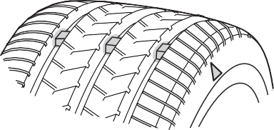
Rotate the tires in the order
shown.
To equalize tire wear and extend tire life, Toyota recommends that tire rotation is carried out at the same interval as tire inspection.
 Do not fail to initialize the tire pressure warning system after tire rotation.
Your vehicle is equipped with a tire pressure warning system that uses tire pressure warning valves and transmitters to detect low tire infla- tion pressure before serious problems arise.
When replacing tires or wheels, tire pressure warning valves and transmitters must also be installed.
When new tire pressure warning valves and transmitters are installed, new ID codes must be registered in the tire pressure warning computer and the tire pressure warning system must be initialized.
When the tire pressure warning system is initialized, the current tire inflation pressure is set as the benchmark pressure.
Park the vehicle in a safe place and turn the engine switch off.
Initialization cannot be performed while the vehicle is moving. Adjust the tire inflation pressure to the specified cold tire inflation pressure level. (P. 548)
Make sure to adjust the tire pressure to the specified cold tire infla- tion pressure level. The tire pressure warning system will operate based on this pressure level.
Turn the engine switch to ON.
Press and hold the tire pres- sure warning reset switch until the tire pressure warn- ing light blinks 3 times.
A message is displayed on the multi-information display. Also, “--” is displayed for inflation pressure of each tire on the multi-information display while the tire pressure warning sys- tem determines the position.
Drive straight (with occasional left and right turns) at approxi- mately 25 mph (40 km/h) or more for approximately 10 to 30 min- utes.
Initialization is complete when the position of each tire is determined and the inflation pressure of each tire is displayed on the multi-infor- mation display.
Initialization may take longer than approximately 30 minutes in cer- tain situations, such as when the vehicle is stopped for a long time at traffic lights, etc. (P. 434)
Every tire pressure warning valve and transmitter has a unique ID code. When replacing a tire pressure warning valve and transmitter, it is necessary to register the ID codes.
To register the ID codes, perform the following procedure:
Press the tire pressure warn- ing reset switch 3 times until the tire pressure warning light blinks slowly 3 times.
Then a message will be dis- played on multi-information display. When registration is being performed, the tire pres- sure warning light will blink for approximately 1 minute then illuminate and “--” will be dis- played for the inflation pres- sure of each tire on the multi- information display.
Drive straight (with occasional left and right turns) at approxi- mately 25 mph (40 km/h) or more for approximately 10 to 30 min- utes.
Registration is complete when the tire pressure warning light turns off and the inflation pressure of each tire is displayed on the multi-information display.
Registration may take longer than approximately 30 minutes in certain situations, such as when the vehicle is stopped for a long time at traffic lights, etc. (P. 434)
After registering the ID codes, make sure to initialize the tire pressure warning system. (P. 427)
Tires should be replaced if:
If you are not sure, consult with your Toyota dealer.
If the ID code of the tire pressure warning valve and transmitter is not reg- istered, the tire pressure warning system will not work properly. After driv- ing for about 20 minutes, the tire pressure warning light blinks for 1 minute and stays on to indicate a system malfunction.
Any tire over 6 years old must be checked by a qualified technician even if it has seldom or never been used or damage is not obvious.
The tire pressure warning system does not replace routine tire inflation pressure checks. Make sure to check tire inflation pressure as part of your routine of daily vehicle checks.
Check that the number given by dividing the maximum load by 1.10 of the replacement tire is greater than 1/2 of the Gross Axle Weight Ratings (GAWR) of either the front axle or the rear axle, whichever is greater.
 For the GAWR, see the Certification Label. For the maximum load of the tire, see the load limit at maximum cold tire inflation pressure mentioned on the sidewall of the tire. (P. 554)
Summer tires are high-speed performance tires best suited to highway driving under dry conditions. Since summer tires do not have the same traction performance as snow tires, summer tires are inadequate for driving on snow-covered or icy roads. For driving on snow-covered roads or icy roads, the use of snow tires is recommended. When install- ing snow tires, be sure to replace all four tires.
All season tires are designed to provide better traction in snow and to be adequate for driving in most winter conditions as well as for use year-round. All season tires, however, do not have adequate traction performance compared with snow tires in heavy or loose snow. Also, all season tires fall short in acceleration and handling performance com- pared with summer tires in highway driving.
For driving on snow-covered roads or icy roads, we recommend using snow tires. If you need snow tires, select tires of the same size, con- struction and load capacity as the originally installed tires. Since your vehicle has radial tires as original equipment, make sure your snow tires also have radial construction. Do not install studded tires without first checking local regulations for possible restrictions. Snow tires should be installed on all wheels. (P. 331)
Initialize the system with the tire inflation pressure adjusted to the speci- fied level.
The effectiveness of the tires as snow tires is lost.
If tire position information is not correctly displayed due to the radio wave conditions, the display may be corrected by driving and changing the radio wave conditions.
Also, make sure the tires are cold before carrying out initialization or tire inflation pressure adjustment.
The warning of the tire pressure warning system will change in accor- dance with the conditions under which it was initialized. For this reason, the system may give a warning even if the tire pressure does not reach a low enough level, or if the pressure is higher than the pressure that was adjusted to when the system was initialized.
initialization will be completed in approximately 10 to 30 minutes. If initial- ization is not complete after driving approximately 10 to 30 minutes, con- tinue driving for a while.
If the inflation pressure of each tire is not displayed after driving for approximately 1 hour, perform the following procedure.
However, in the following situations, the tire inflation pressure will not be recorded and the system will not operate properly. Perform initialization again.
If the inflation pressure of each tire is still not displayed, have the vehicle inspected by your Toyota dealer.
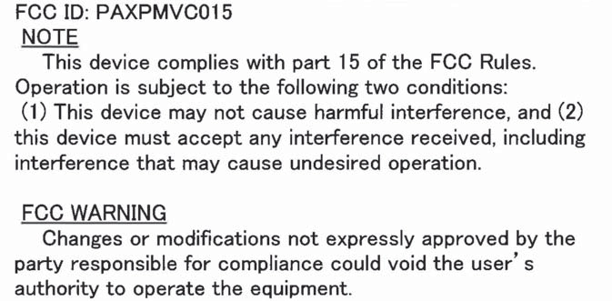
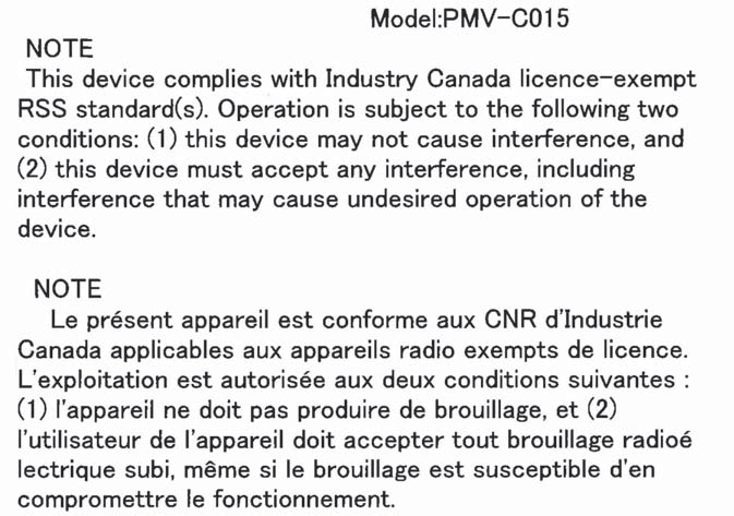
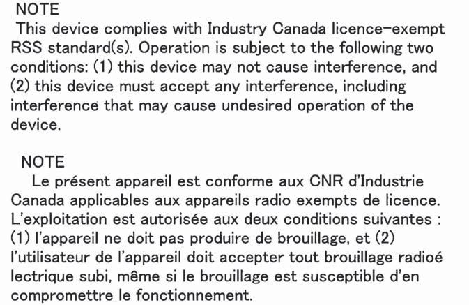
 Tire pressure warning system certification
For vehicles sold in the U.S.A.

For vehicles sold in Canada
Model: PMV-E000
WARNING
Observe the following precautions to prevent accidents.
Failure to do so may cause damage to parts of the drive train as well as dangerous handling characteristics, which may lead to an accident resulting in death or serious injury.
Do not use tires if you do not know how they were used previously.
Do not operate the tire pressure warning reset switch without first adjusting the tire inflation pressure to the specified level. Otherwise, the tire pressure warning light may not come on even if the tire inflation pressure is low, or it may come on when the tire inflation pressure is actually normal.
NOTICE
When a tire is repaired with liquid sealants, the tire pressure warning valve and transmitter may not operate properly. If a liquid sealant is used, contact your Toyota dealer or other qualified service shop as soon as possible. Make sure to replace the tire pressure warning valve and transmitter when replacing the tire. (P. 427)
Take particular care when driving on roads with loose surfaces or pot- holes.
These conditions may cause losses in tire inflation pressure, reducing the cushioning ability of the tires. In addition, driving on rough roads may cause damage to the tires themselves, as well as the vehicle’s wheels and body.
Do not continue driving, or your tires and/or wheels may be ruined.
The recommended cold tire infla- tion pressure and tire size are dis- played on the tire and loading information label. (P. 548)
1 Tire valve
Tire pressure gauge
Remove the tire valve cap.
Press the tip of the tire pressure gauge onto the tire valve. Read the pressure using the gauge gradations.
If the tire inflation pressure is not at the recommended level, adjust the pressure.
If you add too much air, press the center of the valve to deflate.
After completing the tire inflation pressure measurement and adjustment, apply soapy water to the valve and check for leakage.
Put the tire valve cap back on.
You should check tire inflation pressure every two weeks, or at least once a month.
Do not forget to check the spare.
Driving with incorrect tire inflation pressure may result in the following:
If a tire needs frequent inflating, have it checked by your Toyota dealer.
When checking tire inflation pressure, observe the following:
If your vehicle has been parked for at least 3 hours or has not been driven for more than 1 mile or 1.5 km, you will get an accurate cold tire inflation pressure reading.
It is difficult to judge if a tire is properly inflated based only on its appear- ance.
When replacing wheels, care should be taken to ensure that they are equivalent to those removed in load capacity, diameter, rim width and inset*.
Replacement wheels are available at your Toyota dealer.
*: Conventionally referred to as “offset”.
Toyota does not recommend using the following:
The wheels of your vehicle are equipped with tire pressure warning valves and transmitters that allow the tire pressure warning system to provide advance warning in the event of a loss in tire inflation pressure. Whenever wheels are replaced, tire pressure warning valves and trans- mitters must be installed. (P. 427)
Align the notch of the wheel and orna- ment.
WARNING
Oil and grease may cause the wheel nuts to be excessively tightened, leading to bolt or disc wheel damage. In addition, the oil or grease can cause the wheel nuts to loosen and the wheel may fall off, causing an accident and resulting in death or serious injury. Remove any oil or grease from the wheel bolts or wheel nuts.
Open the glove box.
Remove the tray.
Remove the cover by sliding up while pulling toward you.
Remove the filter cover.
Pull the filter out of the filter out- let.
Remove the air conditioning filter and replace it with a new one.
The “UP” marks shown on the fil- ter should be pointing up.
Inspect and replace the air conditioning filter according to the maintenance schedule. In dusty areas or areas with heavy traffic flow, early replacement may be required. (For scheduled maintenance information, please refer to the “Scheduled Maintenance Guide” or “Owner’s Manual Supplement”.)
The filter may be clogged. Check the filter and replace if necessary.
Vehicles without a smart key system Remove the cover.
To prevent damage to the key,
cover the tip of the screwdriver with a rag.
To prevent the buttons from being disassembled, face the button sur- face downward.
: If equipped
Insert a new battery with the “+” terminal facing up.
Remove the cover.
To prevent damage to the key, cover the tip of the screwdriver with a rag.
Insert a new battery with the “+”ter- minal facing up.
The following symptoms may occur:
Engine compartment
Push the tab in and lift the cover off.
Under the instrument panel Remove the cover.
Remove the fuse with the pull- out tool.
Only type A fuse can be removed using the pullout tool.
Normal fuse Blown fuse
Type A and B:
Replace the blown fuse with a new fuse of an appropriate amperage rat- ing. The amperage rating can be found on the fuse box cover.
Type C:
Contact your Toyota dealer.

 Type A Type B
Type C
The fuses are designed to blow, protecting the wiring harness from damage.
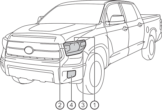 Front
FrontHeadlights (bulb type)
Front turn signal lights/parking lights (bulb type) Front side marker lights
Fog lights (bulb type) (if equipped)
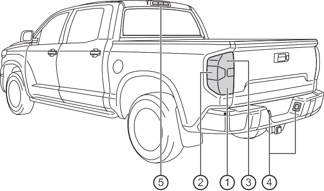 Rear
RearStop/tail and rear side marker lights Back up lights
Rear turn signal lights License plate lights
High mounted stoplight and cargo lamps
To allow enough working space, turn the steering wheel to the opposite side of the bulb to be replaced. Remove the screws and fender liner clip, and remove the fender liner.
Turn the steering wheel to the left when replacing the right side light bulb, and turn the steering wheel to the right when replac- ing the left side light bulb.
Remove the rubber cover.
Release the bulb retaining spring.
Remove the bulb.
Set the new light bulb.
To install a new bulb, align tabs of the bulb with the cutouts of the mounting hole.
Install the rubber cover.
When installing the rubber cover: P. 471
Reinstall the fender liner and install the screws and clip.
Turn the bulb base counter- clockwise.
Remove the light bulb.
Turn the bulb base counter- clockwise.
Remove the light bulb.
To allow enough working space, turn the steering wheel to the opposite side of the bulb to be replaced. Remove the screws and fender liner clip, and remove the fender liner.
Turn the steering wheel to the left when replacing the right side light bulb, and turn the steering wheel to the right when replac- ing the left side light bulb.
Remove the light bulb.
Reinstall the fender liner and install the screws and clip.
To allow enough working space, turn the steering wheel to the opposite side of the bulb to be replaced. Remove the screws and fender liner clip, and remove the fender liner.
Turn the steering wheel to the left when replacing the right side light bulb, and turn the steering wheel to the right when replac- ing the left side light bulb.
Turn the bulb counterclock- wise.
Set the new light bulb.
Align the 3 tabs on the light bulb with the mounting, and insert.
Turn it clockwise to set.
Shake the bulb base gently to check that it is not loose, turn the fog lights, on once and visu- ally confirm that no light is leak- ing through the mounting.
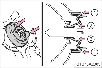
 Remove the bolts and rear combination assembly.
Turn the bulb bases counter- clockwise.
Rear turn signal light Back-up light
Stop/tail and rear side marker light
Remove the light bulb. Rear turn signal light Back-up light
Stop/tail and rear side marker light
Turn the bulb base counter- clockwise.
Remove the light bulb.
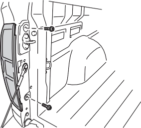
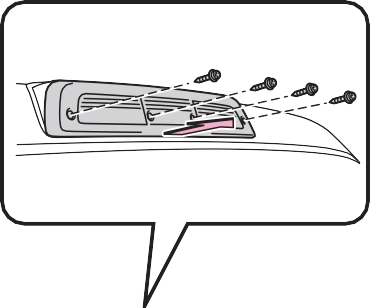 Remove the screws and cover.
Remove the light bulb.
High mounted stoplight Cargo lamps
When reinstalling the outer lens, confirm that the packing is prop- erly seated in the groove on the housing.
Ensure the rubber cover is securely attached.
 Fit the rubber cover outer circumfer- ence in firmly.
Fit the rubber cover around the light bulb in until the light bulb plug can be seen.
Confirm that they are properly engaged with the bulb base and that there is no light leakage.
The headlights (LED type), front fog lights (LED type), parking lights (LED type), daytime running light and side turn signal lights consist of a number of LEDs. If any of the LEDs burn out, take your vehicle to your Toyota dealer to have the light replaced.
Temporary condensation build-up on the inside of the headlight lens does not indicate a malfunction. Contact your Toyota dealer for more information in the following situations:
WARNING
The bulbs become very hot and may cause burns.
Also, if the bulb is scratched or dropped, it may blow out or crack.
Doing so could result in electric shock and serious injury.
When trouble arises
Emergency flashers 474
If your vehicle has to be stopped in
an emergency 475
If the vehicle is trapped
in rising water 477
7
If your vehicle needs to
be towed 478
If you think something is
wrong 483
Fuel pump shut off
system 484
If a warning light turns on or a warning buzzer
sounds 485
If a warning message is displayed 493
If you have a flat tire 506
If the engine will not start 521
If the electronic key does not operate properly (vehicles with
a smart key system) 523
If the vehicle battery is discharged 525
If your vehicle overheats 529
If the vehicle becomes
stuck 532
Download Manual