Using the driving support systems
*: If equipped

P.195
*: If equipped
*: If equipped
P.233
*: If equipped
*: If equipped
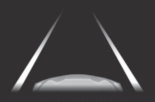
Two types of sensors, located behind the front grille and wind- shield, detect information neces- sary to operate the drive assist systems.
|
|
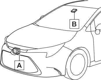
Radar sensor Front camera
181
4-5. Using the driving support systems
183
|
|
|
Do not allow liquids to contact the front camera.
Do not allow bright lights to shine into the front camera.
Do not dirty or damage the front camera.
When cleaning the inside of the windshield, do not allow glass cleaner to contact the lens of the front camera. Also, do not touch the lens. If the lens is dirty or damaged, contact your Toyota dealer. Do not subject the front camera to a strong impact.
Do not change the installation position or direction of the front camera or remove it.
Do not disassemble the front camera.
Do not modify any components of the vehicle around the front camera (inside rear view mirror, etc.) or ceiling.
Do not attach any accessories to the hood, front grille or front bumper that may obstruct the front camera. Contact your Toy- ota dealer for details.
If a surfboard or other long object is to be mounted on the roof, make sure that it will not obstruct the front camera.
Do not modify the headlights or other lights.
|
 WARNING
Except for vehicles sold in Canada
For vehicles sold in Canada
185
A system may be temporarily unavailable or there may be a malfunction in the system.
If the message does not disappear, contact your Toyota dealer.
|
Situation |
Actions |
|
When the area around a sensor is covered with dirt, moisture (fogged up, covered with condensation, ice, etc.), or other foreign matter |
To clean the part of the windshield in front of the front camera, use the windshield wipers or the windshield defogger of the air conditioning sys- tem (P.387, 392). |
|
Situation |
Actions |
|
When the temperature around the front camera is outside of the opera- tional range, such as when the vehi- cle is in the sun or in an extremely cold environment |
If the front camera is hot, such as after the vehicle had been parked in the sun, use the air conditioning sys- tem to decrease the temperature around the front camera. If a sunshade was used when the vehicle was parked, depending on its type, the sunlight reflected from the surface of the sunshade may cause the temperature of the front camera to become excessively high. |
|
If the front camera is cold, such after the vehicle is parked in an extremely cold environment, use the air condi- tioning system to increase the tem- perature around the front camera. |
|
|
The area in front of the front camera is obstructed, such as when the hood is open or a sticker is attached to the part of the windshield in front of the front camera. |
Close the hood, remove the sticker, etc. to clear the obstruction. |
If the message does not disappear, contact your Toyota dealer.
187
multi-information display to urge the driver to take evasive action.
When the system determines that the possibility of a frontal collision is high, the system applies greater braking force in relation to how strongly the brake pedal is depressed.
If the system determines that the possibility of a frontal colli- sion is extremely high, the brakes are automatically applied to help avoid the collision or reduce the impact of the colli- sion.
4-5. Using the driving support systems
189
enabled/disabled on  (P.548) of the multi-informa- tion display.
The system is automatically enabled each time the engine switch is turned to ON.
The pre-collision warning timing
can be changed on  (P.548) of the multi-informa- tion display.
The warning timing setting is retained when the engine switch is turned off. However, if the pre-colli- sion system is disabled and
re-enabled, the operation timing will return to the default setting (mid- dle).
This is the default setting.
1 Early
The pre-collision system is enabled and the system determines that the pos- sibility of a frontal collision with a detected object is high.
Each function is operational at the following speed
|
Detectable objects |
Vehicle speed |
Relative speed between your vehicle and object |
|
Vehicles |
Approx. 7 to 110 mph (10 to 180 km/h) |
Approx. 7 to 110 mph (10 to 180 km/h) |
|
Bicyclists and pedestri- ans |
Approx. 7 to 50 mph (10 to 80 km/h) |
Approx. 7 to 50 mph (10 to 80 km/h) |
|
Detectable objects |
Vehicle speed |
Relative speed between your vehicle and object |
|
Vehicles |
Approx. 20 to 110 mph (30 to 180 km/h) |
Approx. 20 to 110 mph (30 to 180 km/h) |
|
Bicyclists and pedestri- ans |
Approx. 20 to 50 mph (30 to 80 km/h) |
Approx. 20 to 50 mph (30 to 80 km/h) |
191
|
Detectable objects |
Vehicle speed |
Relative speed between your vehicle and object |
|
Vehicles |
Approx. 7 to 110 mph (10 to 180 km/h) |
Approx. 7 to 110 mph (10 to 180 km/h) |
|
Bicyclists and pedestri- ans |
Approx. 7 to 50 mph (10 to 80 km/h) |
Approx. 7 to 50 mph (10 to 80 km/h) |
The system may not operate in the following situations:
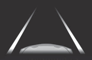
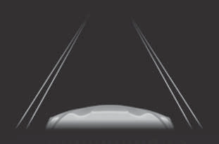
The system detects objects based on their size, profile, motion, etc. However, an object may not be detected depending on the sur- rounding brightness and the motion, posture, and angle of the detected object, preventing the system from operating properly. (P.192)
The illustration shows an image of detectable objects.
If either of the following occur while the pre-collision braking function is operating, it will be canceled:
(road sign, billboard, etc.)
193
swerving, acceleration or deceler- ation)
rear end, such as a low bed trailer
sively worn, improper tire inflation pressure, etc.)
pre-collision braking functions are also disabled.
multi-information display.
195
*: If equipped
4-5. Using the driving support systems
197
|
There are shadows on the road that run parallel with, or cover, the white (yellow) lines.
The vehicle is driven in an area without white (yellow) lines, such as in front of a tollgate or checkpoint, or at an intersec- tion, etc.
The white (yellow) lines are cracked, “Botts’ dots”, “Raised pavement marker” or stones are present.
The white (yellow) lines cannot be seen or are difficult to see due to sand, etc.
The vehicle is driven on a road surface that is wet due to rain, puddles, etc.
The traffic lines are yellow (which may be more difficult to recognize than lines that are white).
The white (yellow) lines cross over a curb, etc.
The vehicle is driven on a bright surface, such as concrete.
If the edge of the road is not clear or straight.
The vehicle is driven on a sur- face that is bright due to reflected light, etc.
The vehicle is driven in an area where the brightness changes suddenly, such as at the entrances and exits of tunnels, etc.
Light from the headlights of an oncoming vehicle, the sun, etc. enters the camera.
The vehicle is driven on a slope.
The vehicle is driven on a road which tilts left or right, or a wind- ing road.
|
that the vehicle might depart from its lane or course*, a warn- ing is displayed on the
multi-information display, and a warning buzzer will sound to alert the driver.
When the warning buzzer sounds, check the area around your vehicle and carefully operate the steering wheel to move the vehicle back to the center of the lane.
Vehicles with a Blind Spot Monitor: When the system determines that the vehicle might depart from its lane and that the possibility of a col- lision with an overtaking vehicle in the adjacent lane is high, the lane departure alert will operate even if the turn signals are operating.
*: Boundary between asphalt and the side of the road, such as grass, soil, or a curb
When the system determines
that the vehicle might depart from its lane or course*, the sys- tem provides assistance as nec- essary by operating the steering wheel in small amounts for a short period of time to keep the vehicle in its lane.
If the system detects that the steer- ing wheel has not been operated for a fixed amount of time or the steering wheel is not being firmly gripped, a warning is displayed on the multi-information display and the function is temporarily can- celed.
Vehicles with a Blind Spot Monitor:  When the system determines that
199
the vehicle might depart from its lane and that the possibility of a col- lision with an overtaking vehicle in the adjacent lane is high, the steer- ing assist function will operate even if the turn signals are operating.
*: Boundary between asphalt and the side of the road, such as grass, soil, or a curb
tion
the multi-information display and the function is temporarily can- celed.
When dynamic radar cruise control with full-speed range is not operat- ing, the lane centering function does not operate.
In situations where the white (yel- low) lane lines are difficult to see or are not visible, such as when in a traffic jam, this function will operate to help follow a preceding vehicle by monitoring the position of the preceding vehicle.
If the system detects that the steer- ing wheel has not been operated for a fixed amount of time or the steering wheel is not being firmly gripped, a warning is displayed on
The LTA indicator illuminates and a message is displayed on the
multi-information display.
Press the LTA switch again to turn the LTA system off.
When the LTA system is turned on or off, operation of the LTA system continues in the same condition the next time the engine is started.
201
The illumination condition of the indicator informs the driver of the system operation status.
Illuminated in white: LTA system is operating.
Illuminated in green: Steering wheel assistance of the steering assist function or lane centering function is operating.
Flashing in orange: Lane departure alert function is operating.
Displayed when the multi-informa- tion display is switched to the driv- ing support system information screen.
Indicates that steering wheel assis- tance of the steering assist function
or lane centering function is operat- ing.
Both outer sides of the lane are dis- played: Indicates that steering wheel assist of the lane centering function is operating.
One outer side of the lane is dis- played: Indicates that steering wheel assist of the steering assist function is operating.
Both outer sides of the lane are flashing: Alerts the driver that their input is necessary to stay in the center of the lane (lane centering function).
Displayed when the multi-informa- tion display is switched to the driv- ing support system information screen.
|
|
Indicates that the system is rec- ognizing white (yellow) lines or a course*. When the vehicle departs from its lane, the white line displayed on the side the vehicle departs from flashes orange.
Inside of displayed lines is black
Indicates that the system is not able to recognize white (yellow) lines or a course* or is temporar- ily canceled.
*: Boundary between asphalt and the side of the road, such as grass, soil, or a curb
Displayed when the multi-informa- tion display is switched to the driv- ing support system information screen.
Indicates that steering assist of the lane centering function is operating by monitoring the position of a pre- ceding vehicle.
When the follow-up cruising display is displayed, if the preceding vehi- cle moves, your vehicle may move in the same way. Always pay care- ful attention to your surroundings and operate the steering wheel as necessary to correct the path of the vehicle and ensure safety.
lane lines or a course*2. (When a white [yellow] line or course*2 is recognized on only one side, the system will operate only for the recognized side.)
*1: The function operates even if the vehicle speed is less than approximately 32 mph (50 km/h) when the lane centering function is operating.
*2: Boundary between asphalt and the side of the road, such as grass, soil, or a curb
This function operates when all of the following conditions are met in addition to the operation conditions for the lane departure alert function.
 of the multi-information display is set to “ON”. (P.548)
203
the following conditions are met.
 of the multi-information display is set to “ON”. (P.548)
This function operates when all of the following conditions are met.
“Lane Center” in  of the
multi-information display are set to “ON”. (P.548)
*: Boundary between asphalt and the side of the road, such as grass, soil, or a curb
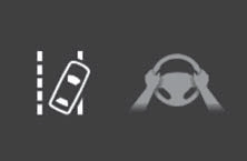
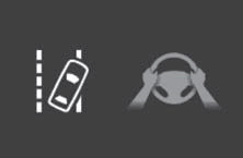 In the following situations, a warning message urging the driver to hold the steering wheel and the symbol shown in the illustration are dis- played on the multi-information dis- play to warn the driver. The warning stops when the system determines that the driver holds the steering wheel. Always keep your hands on the steering wheel when using this system, regardless of warnings.
If the driver continues to keep their hands off of the steering wheel, the buzzer sounds, the driver is warned and the function is temporarily can- celed. This warning also operates in the same way when the driver con- tinuously operates the steering wheel only a small amount.
Depending on the vehicle condition and road conditions, the warning may not operate. Also, if the system determines that the vehicle is driv- ing around a curve, warnings will occur earlier than during
straight-lane driving.
If the driver continues to keep their hands off of the steering wheel and the steering wheel assist is operat- ing, the buzzer sounds and the driver is warned. Each time the buzzer sounds, the continuing time of the buzzer becomes longer.
When the system determines that the vehicle is swaying while the vehicle sway warning function is operating, a buzzer sounds and a warning message urging the driver to rest and the symbol shown in the illustration are simultaneously dis- played on the multi-information dis- play.
 Depending on the vehicle and road conditions, the warning may not operate.
If the following warning message is displayed on the multi-information display and the LTA indicator illumi- nates in orange, follow the appropri- ate troubleshooting procedure. Also, if a different warning message is displayed, follow the instructions displayed on the screen.
The system may not be operating properly. Have the vehicle inspected by your Toyota dealer.
The system is temporarily canceled due to a malfunction in a sensor other than the front camera. Turn the LTA system off, wait for a little while, and then turn the LTA system back on.
The function cannot be used as the vehicle speed exceeds the LTA operation range. Drive slower.
205
The system needs to be initialized. To initialize the system, drive the vehicle straight ahead for 5 seconds or more at a speed of approximately 22 mph (35 km/h) or more.
Function settings can be changed. (P.548)
*: If equipped
4-5. Using the driving support systems
207
|
The vehicle is driven in an area without white (yellow) lines, such as in front of a tollgate or checkpoint, or at an intersec- tion, etc.
The white (yellow) lines are cracked, “Botts’ dots”, “Raised pavement marker” or stones are present.
The white (yellow) lines cannot be seen or are difficult to see due to sand, etc.
The vehicle is driven on a road surface that is wet due to rain, puddles, etc.
The traffic lines are yellow (which may be more difficult to recognize than lines that are white).
The white (yellow) lines cross over a curb, etc.
The vehicle is driven on a bright surface, such as concrete.
If the edge of the road is not clear or straight.
The vehicle is driven on a sur- face that is bright due to reflected light, etc.
The vehicle is driven in an area where the brightness changes suddenly, such as at the entrances and exits of tunnels, etc.
Light from the headlights of an oncoming vehicle, the sun, etc. enters the camera.
The vehicle is driven on a slope.
The vehicle is driven on a road which tilts left or right, or a wind- ing road.
The vehicle is driven on an unpaved or rough road.
|
When the warning buzzer sounds, check the area around your vehicle and carefully operate the steering wheel to move the vehicle back to the center of the lane.
Vehicles with a Blind Spot Monitor: When the system determines that the vehicle might depart from its lane and that the possibility of a col- lision with an overtaking vehicle in the adjacent lane is high, the lane departure alert will operate even if the turn signals are operating.
*: Boundary between asphalt and the side of the road, such as grass, soil, or a curb
multi-information display, and a warning buzzer will sound to alert the driver.
When the system determines that the vehicle might depart from its lane or course*, the sys- tem provides assistance as nec- essary by operating the steering wheel in small amounts for a short period of time to keep the
209
If the system detects that the steer- ing wheel has not been operated for a fixed amount of time or the steering wheel is not being firmly gripped, a warning is displayed on the multi-information display and the function is temporarily can- celed.
Vehicles with a Blind Spot Monitor: When the system determines that the vehicle might depart from its lane and that the possibility of a col- lision with an overtaking vehicle in the adjacent lane is high, the steer- ing assist function will operate even if the turn signals are operating.
*: Boundary between asphalt and the side of the road, such as grass, soil, or a curb
buzzer will sound and a mes- sage will be displayed on the multi-information display to alert the driver.
Press the LDA switch to turn the LDA system on.
The LDA indicator illuminates and a message is displayed on the
multi-information display.
Press the LDA switch again to turn the LDA system off.
When the LDA system is turned on or off, operation of the LDA system continues in the same condition the next time the engine is started.
Lane departure alert function display
Displayed when the multi-informa- tion display is switched to the driv- ing support system information screen.
|
|
LDA indicator
The illumination condition of the indicator informs the driver of the system operation status.
Illuminated in white: LDA system is operating.
Illuminated in green: Steering wheel assistance of the steering assist function is operating.
Flashing in orange: Lane departure alert function is operating.
Displayed when the multi-informa- tion display is switched to the driv- ing support system information screen.
Indicates that steering wheel assis- tance of the steering assist function is operating.
Inside of displayed lines is black
|
|
Indicates that the system is not able to recognize white (yellow) lines or a course* or is temporar- ily canceled.
211
*: Boundary between asphalt and the side of the road, such as grass, soil, or a curb
mately 9.8 ft. (3 m) or more.
*: Boundary between asphalt and the side of the road, such as grass, soil, or a curb
This function operates when all of the following conditions are met in addition to the operation conditions for the lane departure alert function.
 of the multi-information display is set to “ON”. (P.548)
 of the multi-information display is set to “ON”. (P.548)
When operation conditions are no longer met, a function may be tem- porarily canceled. However, when the operation conditions are met again, operation of the function is automatically restored. (P.211)
*: Boundary between asphalt and the side of the road, such as grass, soil, or a curb
 In the following situations, a warning message urging the driver to hold the steering wheel and the symbol shown in the illustration are dis- played on the multi-information dis- play to warn the driver. The warning stops when the system determines that the driver holds the steering wheel. Always keep your hands on the steering wheel when using this system, regardless of warnings.
If the driver continues to keep their hands off of the steering wheel, the buzzer sounds, the driver is warned and the function is temporarily can- celed. This warning also operates in the same way when the driver con- tinuously operates the steering wheel only a small amount.
Depending on the vehicle condition and road conditions, the warning may not operate. Also, if the system determines that the vehicle is driv-
ing around a curve, warnings will occur earlier than during
straight-lane driving.
If the driver continues to keep their hands off of the steering wheel and the steering wheel assist is operat- ing, the buzzer sounds and the driver is warned. Each time the buzzer sounds, the continuing time of the buzzer becomes longer.
When the system determines that the vehicle is swaying while the vehicle sway warning function is operating, a buzzer sounds and a warning message urging the driver to rest and the symbol shown in the illustration are simultaneously dis- played on the multi-information dis- play.
 Depending on the vehicle and road conditions, the warning may not operate.
If the following warning message is displayed on the multi-information display and the LDA indicator illumi- nates in orange, follow the appropri- ate troubleshooting procedure. Also, if a different warning message is displayed, follow the instructions displayed on the screen.
The system may not be operating properly. Have the vehicle inspected by your Toyota dealer.
The system is temporarily canceled
213
due to a malfunction in a sensor other than the front camera. Turn the LDA system off, wait for a little while, and then turn the LDA system back on.
The function cannot be used as the vehicle speed exceeds the LDA operation range. Drive slower.
The LDA system cannot be used as the vehicle speed is less than approximately 32 mph (50 km/h).
Drive the vehicle at approximately 32 mph (50 km/h) or more.
The system needs to be initialized. To initialize the system, drive the vehicle straight ahead for 5 seconds or more at a speed of approximately 22 mph (35 km/h) or more.
Function settings can be changed. (P.548)
*: If equipped
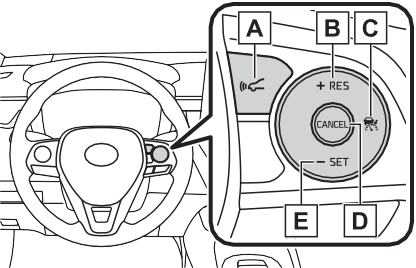
Set speed Indicators
|
|

Vehicle-to-vehicle distance switch
“+RES” switch
Cruise control main switch Cancel switch
“-SET” switch
|
|
|
Before using dynamic radar cruise control with full-speed range
Driving safely is the sole responsibility of the driver. Do not rely solely on the system, and drive safely by always pay- ing careful attention to your sur- roundings.
The dynamic radar cruise con- trol with full-speed range pro- vides driving assistance to reduce the driver’s burden. However, there are limitations to the assistance provided.
Read the following conditions carefully. Do not overly rely on this system and always drive carefully. When the sensor may not be correctly detecting the vehicle ahead: P.222
|
 WARNING
 4-5. Using the driving support systems
215
This mode employs a radar to detect the presence of vehicles up to approximately 328 ft. (100 m) ahead, determines the current vehi- cle-to-vehicle following distance, and operates to maintain a suitable following distance from the vehicle ahead. The desired vehi-
cle-to-vehicle distance can also be set by operating the vehi- cle-to-vehicle distance switch.
When driving on downhill slopes, the vehicle-to-vehicle distance may become shorter.
The vehicle travels at the speed set by the driver.
When a vehicle is detected running ahead of you, the system automatically decelerates your vehicle. When a greater reduction in vehicle speed is nec- essary, the system applies the brakes (the stop lights will come on at this time). The system will respond to changes in the speed of the vehicle ahead in order to maintain the vehicle-to-vehicle distance set by the driver. Approach warning warns you when the system cannot decelerate suffi- ciently to prevent your vehicle from closing in on the vehicle ahead.
When the vehicle ahead of you stops, your vehicle will also stop (vehicle is stopped by system control). After the vehicle ahead starts off, pressing the “+RES” switch or depressing the accelerator pedal (start-off operation) will resume follow-up cruising. If the start-off operation is not performed, system control continues to keep your vehicle stopped.
217
When the turn signal lever is operated and your vehicle moves to a left lane while driving at 50 mph (80 km/h) or more, the vehicle will quickly acceler- ate to help to overtake a passing vehicle.
When there are no longer any preceding vehicles driving slower than the set speed
The system accelerates until the set speed is reached. The system then returns to constant speed cruising.
Dynamic radar cruise control indi- cator will come on and a message will be displayed on the multi-infor- mation display. Press the switch again to deactivate the cruise con- trol.
If the cruise control main switch is pressed and held for 1.5 seconds or more, the system turns on in constant speed control mode. (P.220)
Cruise control “SET” indicator will come on.
The vehicle speed at the moment the switch is released becomes the set speed.
|
|

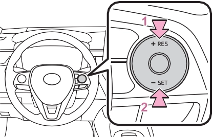
1 Increases the speed (Except when the vehicle has been stopped by system control in
vehicle-to-vehicle distance control mode)
2 Decreases the speed
Fine adjustment: Press the switch.
Large adjustment: Press and hold the switch to change the speed, and release when the desired speed is reached.
For the U.S. mainland and Hawaii
Fine adjustment: By 1 mph (1.6 km/h)*1 or 1 km/h (0.6 mph)*2 each time the switch is pressed
Large adjustment: Increases or decreases in 1 mph (1.6 km/h)*1 or 1 km/h (0.6 mph)*2 increments for as long as the switch is held
Fine adjustment: By 1 mph (1.6 km/h)*1 or 1 km/h (0.6 mph)*2 each time the switch is pressed
Large adjustment: Increases or decreases in 5 mph (8 km/h)*1 or 5 km/h (3.1 mph)*2 increments for as long as the switch is held
Fine adjustment: By 1 mph (1.6 km/h)*1 or 1 km/h (0.6 mph)*2 each time the switch is pressed
Large adjustment: The speed will
continue to change while the switch is held.
*1: When the set speed is shown in “MPH”
*2: When the set speed is shown in “km/h”
The vehicle-to-vehicle distance is set automatically to long mode when the engine switch is turned to ON.
If a vehicle is running ahead of you,
the preceding vehicle mark will also be displayed.
219
Vehicle-to-vehicle distance increases/decreases in accor- dance with vehicle speed. When the vehicle is stopped by system control, the vehicle stops at a certain vehicle-to-vehicle dis- tance depending on the situa- tion.
After the vehicle ahead of you starts off, press the “+RES” switch.
Your vehicle will also resume follow-up cruising if the acceler-
ator pedal is depressed after the vehicle ahead of you starts off.
|
|
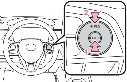

 Pressing the cancel switch cancels the speed control.
The speed control is also canceled when the brake pedal is depressed. (When the vehicle has been stopped by system control, depressing the brake pedal does not cancel the setting.)
When your vehicle is too close
to a vehicle ahead, and suffi- cient automatic deceleration via the cruise control is not possi-
ble, the display will flash and the buzzer will sound to alert the driver. An example of this would be if another driver cuts in front of you while you are following a vehicle. Depress the brake pedal to ensure an appropriate vehicle-to-vehicle distance.
In the following instances, warn- ings may not occur even when the vehicle-to-vehicle distance is small.
When constant speed control mode is selected, your vehicle will maintain a set speed without controlling the vehicle-to-vehi- cle distance. Select this mode only when vehicle-to-vehicle dis- tance control mode does not function correctly due to a dirty radar, etc.
Immediately after the switch is pressed, the dynamic radar cruise control indicator will come on. After- wards, it switches to the cruise con- trol indicator.
Switching to constant speed control mode is only possible when operat- ing the switch with the cruise con- trol off.
Cruise control “SET” indicator will
221
come on.
The vehicle speed at the moment the switch is released becomes the set speed.
Adjusting the speed setting:
P.217
Canceling and resuming the speed setting: P.219
The vehicle can accelerate by oper- ating the accelerator pedal. After accelerating, the set speed resumes. However, during vehi-
cle-to-vehicle distance control mode, the vehicle speed may decrease below the set speed in order to maintain the distance to the preceding vehicle.
approximately 3 seconds after the switch is pressed.
Vehicle-to-vehicle distance control mode is automatically canceled in the following situations.
If vehicle-to-vehicle distance control mode is automatically canceled for any reasons other than the above, there may be a malfunction in the system. Contact your Toyota dealer.
Constant speed control mode is automatically canceled in the follow- ing situations:
automatically canceled for any rea-
sons other than the above, there may be a malfunction in the system. Contact your Toyota dealer.
A brake operation sound may be heard and the brake pedal response may change, but these are not mal- functions.
Warning messages and buzzers are used to indicate a system malfunc- tion or to inform the driver of the need for caution while driving. If a warning message is shown on the multi-information display, read the message and follow the instructions. (P.185, 490)
In the case of the following and depending on the conditions, oper- ate the brake pedal when decelera- tion of the system is insufficient or operate the accelerator pedal when acceleration is required.
As the sensor may not be able to correctly detect these types of vehi- cles, the approach warning (P.219) may not be activated.
In the case of the following condi- tions, operate the brake pedal (or accelerator pedal, depending on the situation) as necessary.
As the sensor may not be able to correctly detect vehicles ahead, the system may not operate properly.
223
*: If equipped
Indicators
|
|
Vehicle-to-vehicle distance switch
“+RES” switch
Cruise control main switch Cancel switch
“-SET” switch
|
|
|
Before using dynamic radar cruise control
Driving safely is the sole responsibility of the driver. Do not rely solely on the system, and drive safely by always pay- ing careful attention to your sur- roundings.
The dynamic radar cruise con- trol provides driving assistance to reduce the driver’s burden. However, there are limitations to the assistance provided.
Read the following conditions carefully. Do not overly rely on this system and always drive carefully. When the sensor may not be correctly detecting the vehicle ahead: P.231
Conditions under which the vehicle-to-vehicle distance con- trol mode may not function cor-
rectly: P.232 |
 WARNING
 4-5. Using the driving support systems
225
This mode employs a radar to detect the presence of vehicles up to approximately 328 ft. (100 m) ahead, determines the current vehi- cle-to-vehicle following distance, and operates to maintain a suitable following distance from the vehicle ahead. The desired vehi-
cle-to-vehicle distance can also be set by operating the vehi- cle-to-vehicle distance switch.
When driving on downhill slopes, the vehicle-to-vehicle distance may become shorter.
The vehicle travels at the speed set by the driver.
When a vehicle is detected running ahead of you, the system automatically decelerates your vehicle. When a greater reduction in vehicle speed is nec- essary, the system applies the brakes (the stop lights will come on at this time). The system will respond to changes in the speed of the vehicle ahead in order to maintain the vehicle-to-vehicle distance set by the driver. Approach warning warns you when the system cannot decelerate suffi- ciently to prevent your vehicle from closing in on the vehicle ahead.
When the turn signal lever is operated and your vehicle moves to a left lane while driving at 50 mph (80 km/h) or more, the vehicle will quickly acceler- ate to help to overtake a passing vehicle.
227
The system accelerates until the set speed is reached. The system then returns to constant speed cruising.
set speed.
Dynamic radar cruise control indi- cator will come on and a message will be displayed on the multi-infor- mation display. Press the switch again to deactivate the cruise con- trol.
If the cruise control main switch is pressed and held for 1.5 seconds or more, the system turns on in constant speed control mode. (P.230)
Cruise control “SET” indicator will come on.
The vehicle speed at the moment the switch is released becomes the
|
|
Fine adjustment: Press the switch.
Large adjustment: Press and hold the switch to change the speed, and release when the desired speed is reached.
decreased as follows:
For the U.S. mainland and Hawaii
Fine adjustment: By 1 mph (1.6 km/h)*1 or 1 km/h (0.6 mph)*2 each
time the switch is pressed Large adjustment: Increases or
decreases in 1 mph (1.6 km/h)*1 or 1 km/h (0.6 mph)*2 increments for as long as the switch is held
Fine adjustment: By 1 mph (1.6 km/h)*1 or 1 km/h (0.6 mph)*2 each time the switch is pressed
Large adjustment: Increases or decreases in 5 mph (8 km/h)*1 or 5 km/h (3.1 mph)*2 increments for as long as the switch is held
Fine adjustment: By 1 mph (1.6 km/h)*1 or 1 km/h (0.6 mph)*2 each time the switch is pressed
Large adjustment: The speed will continue to change while the switch is held.
*1: When the set speed is shown in “MPH”
*2: When the set speed is shown in “km/h”
vehicle-to-vehicle distance as follows:
The vehicle-to-vehicle distance is set automatically to long mode when the engine switch is turned to ON.
If a vehicle is running ahead of you,
the preceding vehicle mark will also be displayed.
Vehicle-to-vehicle distance increases/decreases in accor- dance with vehicle speed.
229
The speed control is also canceled when the brake pedal is depressed.
However, cruise control does not resume when the vehicle speed is approximately 16 mph (25 km/h) or less.
In the following instances, warn- ings may not occur even when the vehicle-to-vehicle distance is small.
come on.
The vehicle speed at the moment the switch is released becomes the set speed.
mode is selected, your vehicle will maintain a set speed without controlling the vehicle-to-vehi- cle distance. Select this mode only when vehicle-to-vehicle dis- tance control mode does not function correctly due to a dirty radar, etc.
Adjusting the speed setting:
P.227
Canceling and resuming the speed setting: P.229
Immediately after the switch is pressed, the dynamic radar cruise control indicator will come on. After- wards, it switches to the cruise con- trol indicator.
Switching to constant speed control mode is only possible when operat- ing the switch with the cruise con- trol off.
Cruise control “SET” indicator will
The vehicle can accelerate by oper- ating the accelerator pedal. After accelerating, the set speed resumes. However, during vehi-
cle-to-vehicle distance control mode, the vehicle speed may decrease below the set speed in order to maintain the distance to the preceding vehicle.
231
Select a shift position according to the vehicle speed. If the engine speed is too high or too low, control may be automatically canceled.
Vehicle-to-vehicle distance control mode is automatically canceled in the following situations.
If vehicle-to-vehicle distance control mode is automatically canceled for any reasons other than the above, there may be a malfunction in the system. Contact your Toyota dealer.
Constant speed control mode is automatically canceled in the follow- ing situations:
If constant speed control mode is automatically canceled for any rea- sons other than the above, there may be a malfunction in the system. Contact your Toyota dealer.
A brake operation sound may be heard and the brake pedal response may change, but these are not mal- functions.
Warning messages and buzzers are used to indicate a system malfunc- tion or to inform the driver of the need for caution while driving. If a warning message is shown on the multi-information display, read the message and follow the instructions. (P.185, 490)
In the case of the following and depending on the conditions, oper- ate the brake pedal when decelera- tion of the system is insufficient or operate the accelerator pedal when acceleration is required.
As the sensor may not be able to correctly detect these types of vehi- cles, the approach warning (P.229) may not be activated.
etc.)
In the case of the following condi- tions, operate the brake pedal (or accelerator pedal, depending on the situation) as necessary.
As the sensor may not be able to correctly detect vehicles ahead, the system may not operate properly.
lanes are narrow
233
|
|
|
|
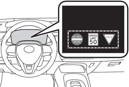
If signs other than speed limit signs are recognized, they will be dis- played in an overlapping stack under the current speed limit sign.
the displayed sign will flash and a buzzer will sound.
Depending on the situation, traf-
The following types of road signs, including electronic signs and blinking signs, are recog- nized.
fic environment (traffic direction, speed unit) may be detected incorrectly and a warning dis- play may not operate properly.
A non-official or a recently intro-
duced traffic sign may not be recog- nized.
Speed limit
Do Not Enter
Stop
Yield
 or
or  of the meter control switches and select

 , then press
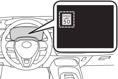
In the following situations, a dis- played speed limit sign will stop being displayed automatically:
In the following situations, do not enter, stop and yield signs will stop being displayed automatically:
In the following situations, RSA does not operate normally and may not recognize signs, display the incorrect sign, etc. However, this does not indicate a malfunction.
235
If the engine switch was last turned
off while a speed limit sign was dis- played on the multi-information dis- play, the same sign displays again when the engine switch is turned to ON.
The system may be malfunctioning. Have the vehicle inspected by your Toyota dealer.
Some functions can be customized. (P.548)
*: If equipped

Turning the Blind Spot Monitor on/off.
When a vehicle is detected in a blind spot of the outside rear view mirrors or approaching rapidly from behind into a blind spot, the outside rear view mirror indicator on the detected side will illuminate. If the turn signal lever is operated toward the detected side, the outside rear view mirror indicator flashes.
Illuminates when the Blind Spot Monitor is enabled
In strong sunlight, the outside rear view mirror indicator may be difficult to see.
Ice, snow, mud, etc., may be attached to the rear bumper around the sensors. (P.238) The system should return to normal operation after removing the ice, snow, mud, etc. from the rear bumper. Addition- ally, the sensors may not operate
237
normally when driving in extremely hot or cold environments.
There may be a sensor malfunction
 Except for vehicles sold in Canada
For vehicles sold in Canada
of misaligned. Have the vehicle inspected by your Toyota dealer.
Some functions can be customized. (P.548)
|
Do not subject a sensor or its surrounding area on the rear bumper to a strong impact.
If a sensor is moved even slightly off position, the system may malfunction and vehicles may not be detected correctly. In the following situations, have your vehicle inspected by your Toyota dealer. A sensor or its surrounding area is subject to a strong impact.
If the surrounding area of a sen- sor is scratched or dented, or part of them has become dis- connected.
Do not disassemble the sensor.
Do not modify the sensor or sur- rounding area on the rear bumper.
If a sensor or the rear bumper needs to be removed/installed or replaced, contact your Toyota dealer.
Do not paint the rear bumper any color other than an official Toyota color.
|
Use the meter control switches to turn on/off the function.
 or
or  to select
  .
.

 Press or to select
  and then press .
4-5. Using the driving support systems
239
Vehicles that are traveling in areas that are not visible using the outside rear view mirrors (the blind spots)
Vehicles that are approaching rapidly from behind in areas that are not visible using the outside rear view mirrors (the blind spots)
The areas that vehicles can be detected in are outlined below.
The range of each detection area is:
Approximately 3.3 ft. (1 m) forward of the rear bumper Approximately 9.8 ft. (3 m) from the rear bumper
Approximately 9.8 ft. (3 m) to 197 ft. (60 m) from the rear bumper*2
*1: The area between the side of the vehicle and 1.6 ft. (0.5 m) from the side of the vehicle cannot be detected.
*2: The greater the difference in speed between your vehicle and the detected vehicle is, the farther away the vehicle will be detected, causing the outside rear view mirror indicator to illuminate or flash.
The Blind Spot Monitor is opera- tional when all of the following con- ditions are met:
The Blind Spot Monitor will detect a vehicle present in the detection area in the following situations:
The Blind Spot Monitor is not designed to detect the following types of vehicles and/or objects:
taken rapidly by your vehicle*
*: Depending on the conditions, detection of a vehicle and/or object may occur.
uneven surfaces
241
will be deactivated when the shift lever is shifted to any posi- tion other than R.
The rear view monitor system
The rear view monitor system screen will be displayed if the shift lever is shifted to R while the engine switch is in ON.
Displays a guide path when the vehicle is being backed straight up. The displayed width is wider than the actual vehicle width.
This line indicates the estimated vehicle center on the ground.
Displays a point approximately 1.5 ft. (0.5 m) (red) from the edge of the bumper.
Displays a point approximately 3 ft. (1 m) (blue) from the edge of the bumper.
243
The rear view monitor system displays an image of the view from the bumper of the rear area of the vehicle.
The image adjustment proce- dure for the rear view monitor system screen is the same as the procedure for adjusting the screen. (P.274)
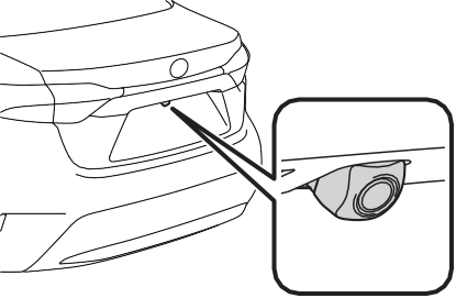 Rear view monitor system camera
The camera for the rear view monitor system is located as shown in the illustration.
If dirt or foreign matter (such as water droplets, snow, mud etc.) is adhering to the camera, it cannot transmit a clear image. In this case, flush it with a large quantity of water and wipe the camera lens clean with a soft and wet cloth.
to be so. Be sure to check visu- ally.
The distances between the vehi- cle width guide lines and the left and right dividing lines of the parking space may not be equal, even when they appear to be so. Be sure to check visually.
The distance guide lines give a distance guide for flat road sur- faces. In any of the following sit- uations, there is a margin of error between the fixed guide lines on the screen and the actual distance/course on the road.
The distance guide lines will appear to be closer to the vehicle than the actual distance. Because of this, objects will appear to be farther
away than they actually are. In the same way, there will be a margin of error between the guide lines and the actual distance/course on the road.
The distance guide lines will appear to be further from the vehicle than the actual distance. Because of this, objects will appear to be closer than they actually are. In the same way, there will be a margin of error between the guide lines and the actual distance/course on the road.
245
When any part of the vehicle sags due to the number of passengers or the distribution of the load, there is a margin of error between the fixed guide lines on the screen and the actual distance/course on the road.
three-dimensional objects
Visually check the surroundings and the area behind the vehicle. In the case shown below, the truck appears to be outside of the vehicle width guide lines and the vehicle does not look as if it hits the truck. However, the rear body of the truck may actually cross over the vehicle width guide lines. In reality if you back up as guided by the vehicle width guide lines, the vehicle may hit the truck.
you will hit the truck. On the screen, it appears that is closest and
is farthest away. However, in reality,
the distance to and is the same, and is farther than and .
Visually check the surroundings and the area behind the vehicle. On the screen, it appears that a truck is
parking at point . However, in reality if you back up to point ,
If the symptom is not resolved by the solution, have the vehicle inspected by your Toyota dealer.
247
|
Symptom |
Likely cause |
Solution |
|
The vehicle is in a dark area
The temperature around the lens is either high or low
The outside tempera-
ture is low There are water drop- lets on the camera
It is raining or humid
Foreign matter (mud etc.) is adhering to the camera
Sunlight or headlights
are shining directly into the camera The vehicle is under fluorescent lights, sodium lights, mer- cury lights etc.
|
If this happens due to |
|
|
these causes, it does |
||
|
not indicate a malfunc- |
||
|
tion. Back up while visu- |
||
|
ally checking the |
||
|
vehicle’s surroundings. |
||
|
The image is difficult to see |
(Use the monitor again once conditions have been improved.) The |
|
|
procedure for adjusting |
||
|
the picture quality of the |
||
|
rear view monitor sys- |
||
|
tem is the same as the |
||
|
procedure for adjusting |
||
|
the screen. (P.274) |
||
|
The image is blurry |
Dirt or foreign matter (such as water droplets, snow, mud etc.) is adhering to the camera. |
Flush the camera with a large quantity of water and wipe the camera lens clean with a soft and wet cloth. |
|
The image is out of alignment |
The camera or sur- rounding area has received a strong impact. |
Have the vehicle inspected by your Toy- ota dealer. |
|
The camera position is out of alignment. |
Have the vehicle inspected by your Toy- ota dealer. |
|
|
The fixed guide lines are very far out of alignment |
The vehicle is tilted (there is a heavy load on the vehicle, tire pressure is low due to a tire puncture, etc.)
The vehicle is used on an incline.
|
If this happens due to these causes, it does not indicate a malfunc- tion. |
|
Back up while visually checking the vehicle’s surroundings. |
4-5. Using the driving support systems
*: If equipped
249
Each time the switch is pressed, the system changes between sport mode and normal mode.
Provides an optimal balance of fuel economy, quietness, and dynamic performance. Suitable for normal driving.
Controls the transmission and engine to provide quick, powerful acceleration. This mode also changes the steering feel, making it suitable for when agile driving response is desired, such as when driving on roads with many curves.
When the sport mode is selected, sport mode indicator comes on.
If the engine switch is turned off after driving in sport mode, the drive
mode will be changed to normal mode.
Generates an increased level of braking force after the brake pedal is depressed when the system detects a panic stop sit- uation
Helps the driver to control skid- ding when swerving suddenly or turning on slippery road sur- faces.
251
Helps to maintain directional stability when swerving on slip- pery road surfaces by con- trolling steering performance.
Helps to maintain drive power and prevent the drive wheels from spinning when starting the vehicle or accelerating on slip- pery roads
Helps to prevent the vehicle from drifting to the outer side by performing inner wheel brake control when attempting to accelerate while turning
Helps to reduce the backward movement of the vehicle when starting on an uphill
Employs an electric motor to reduce the amount of effort needed to turn the steering wheel.
When the SRS airbag sensor detects a collision and the sys- tem operates, the brakes and brake lights are automatically
controlled to reduce the vehicle speed and help reduce the pos- sibility of further damage due to a secondary collision.
The slip indicator light will flash while the TRAC/VSC systems are operating.
If the vehicle gets stuck in mud, dirt or snow, the TRAC system may reduce power from the engine to the
wheels. Pressing  to turn the system off may make it easier for you to rock the vehicle in order to free it.
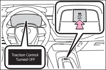
To turn the TRAC system off, quickly press and release  .
.
The “Traction Control Turned OFF” will be shown on the multi-informa- tion display.
Press  again to turn the system back on.
To turn the TRAC and VSC systems
off, press and hold  for more than 3 seconds while the vehicle is stopped.
The VSC OFF indicator light will come on and the “Traction Control Turned OFF” will be shown on the multi-information display.*
Press  again to turn the system back on.
*: PCS will also be disabled (only Pre-Collision warning is avail- able). The PCS warning light will come on and a message will be displayed on the multi-information display. (P.194)
been disabled even if  has not been pressed
TRAC is temporary deactivated. If the information continues to show, contact your Toyota dealer.
When the following four conditions are met, the hill-start assist control will operate:
depressed
The hill-start assist control will turn off in any of the following situations:
None of these indicates that a malfunction has occurred.
253
When the Active Cornering Assist is operated, operation sounds and vibrations may be generated from the brake system, but this is not a malfunction.
When the steering wheel is oper- ated, a motor sound (whirring sound) may be heard. This does not indicate a malfunction.
After turning the TRAC and VSC systems off, the systems will be automatically re-enabled in the fol- lowing situations:
If both the TRAC and VSC sys- tems are turned off, automatic re-enabling will not occur when vehicle speed increases.
The system operates when the fol- lowing occurs.
The effectiveness of the EPS sys- tem is reduced to prevent the sys- tem from overheating when there is frequent steering input over an extended period of time. The steer- ing wheel may feel heavy as a result. Should this occur, refrain from excessive steering input or stop the vehicle and turn the engine
off. The EPS system should return to normal within 10 minutes.
The system operates when the SRS airbag sensor detects a collision while the vehicle is in motion.
However, the system does not oper- ate in any of the following situations.
The system is automatically can- celed in any of the following situa- tions.
|
|
|
The ABS does not operate effectively when
The limits of tire gripping perfor- mance have been exceeded (such as excessively worn tires on a snow covered road).
The vehicle hydroplanes while driving at high speed on wet or slick roads.
Stopping distance when the ABS is operating may exceed that of normal conditions
The ABS is not designed to shorten the vehicle’s stopping dis- tance. Always maintain a safe dis- tance from the vehicle in front of you, especially in the following sit- uations: When driving on dirt, gravel or snow-covered roads
|
 WARNING
Winter driving tips
Download Manual