Do-it-yourself maintenance
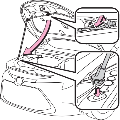
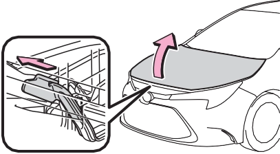
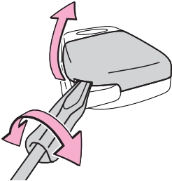
Hood
The hood will pop up slightly.
|
|
|
|
|
|
|
When closing the hood
Be sure to return the support rod to its clip before closing the hood. Closing the hood with the support rod not clipped could cause the hood to bend. |
 NOTICE
435
|
|
Engine compartment
1.8 L 4-cylinder (2ZR-FAE) engine
Washer fluid tank (P.443) Engine coolant reservoir (P.436) Fuse boxes (P.461)
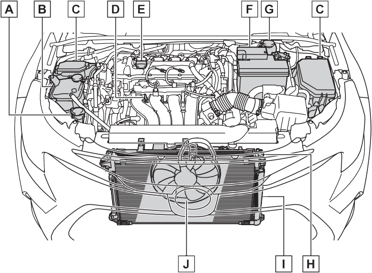 Engine oil level dipstick (P.437) Engine oil filler cap (P.438) Battery (P.442)
Brake fluid reservoir (P.441) Radiator (P.440) Condenser (P.440)
Electric cooling fan
7-3. Do-it-yourself maintenance
2.0 L 4-cylinder (M20A-FKS) engine
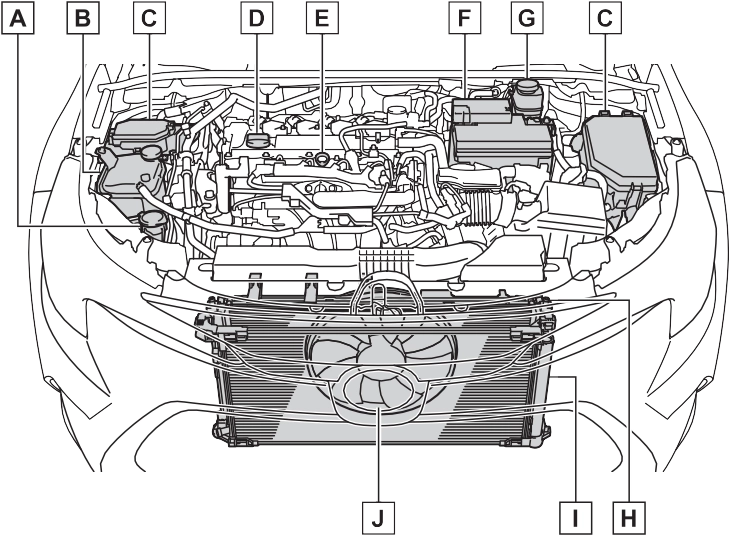
Washer fluid tank (P.443) Engine coolant reservoir (P.436) Fuse boxes (P.461)
Engine oil filler cap (P.438) Engine oil level dipstick (P.437) Battery (P.442)
Brake fluid reservoir (P.441) Radiator (P.440) Condenser (P.440)
Electric cooling fan
437
With the engine at operating temperature and turned off, check the oil level on the dip- stick.
1 Park the vehicle on level ground. After warming up the engine and turning it off, wait more than 5 minutes for the oil to drain back into the bot- tom of the engine.
1.8 L 4-cylinder (2ZR-FAE) engine
Normal Excessive
The shape of the dipstick may differ depending on the type of vehicle or engine.
Low
Make sure to check the oil type and prepare the items needed before adding oil.
P.526, 527
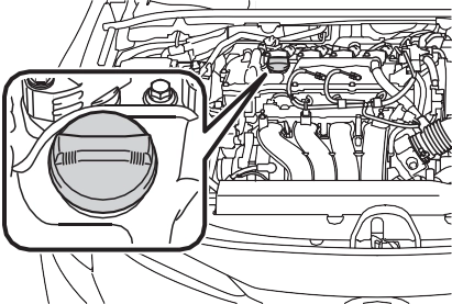
Clean funnel
If the oil level is below or near the low level mark, add engine oil of the same type as that already in the engine.
1.8 L 4-cylinder (2ZR-FAE) engine
|
|
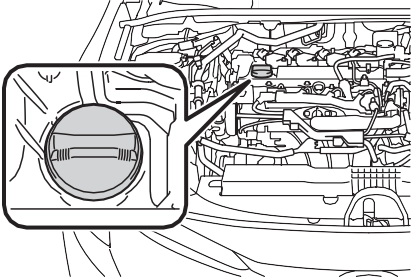
 2.0 L 4-cylinder (M20A-FKS) engine
|
|
 A certain amount of engine oil will be consumed while driving. In the following situations, oil consump- tion may increase, and engine oil may need to be refilled in between oil maintenance intervals.
439
Visually check the radiator, hoses, engine coolant reservoir caps, drain
if it is between the “FULL” and “LOW” lines on the reservoir when the engine is cold.
Reservoir cap “FULL” line “LOW” line
If the level is on or below the “LOW”
line, add coolant up to the “FULL” line. (P.519)
Only use “Toyota Super Long Life Coolant” or a similar high quality ethylene glycol based non-silicate, non-amine, non-nitrite, and
non-borate coolant with long-life hybrid organic acid technology.
U.S.A.:
“Toyota Super Long Life Coolant” is a mixture of 50% coolant and 50% deionized water. (Minimum tem- perature: -31°F [-35°C])
Canada:
“Toyota Super Long Life Coolant” is a mixture of 55% coolant and 45% deionized water. (Minimum tem- perature: -44°F [-42°C])
For more details about coolant, con- tact your Toyota dealer.
cock and water pump.
If you cannot find a leak, have your Toyota dealer test the cap and check for leaks in the cooling sys- tem.
|
|
|
When the engine is hot
Do not remove the engine coolant reservoir cap. The cooling system may be under pressure and may spray hot cool- ant if the cap is removed, causing serious injuries, such as burns. |
 WARNING
|
|
|
When adding coolant
Coolant is neither plain water nor straight antifreeze. The correct mixture of water and antifreeze must be used to provide proper lubrication, corrosion protection and cooling. Be sure to read the antifreeze or coolant label. If you spill coolant
Be sure to wash it off with water to prevent it from damaging parts or paint. |
 NOTICE
 2 Disconnect the claws and remove the service cover.
441
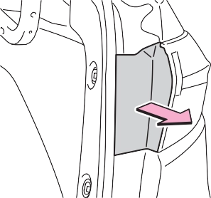
1 Slide and lift up the rubber strip to partly remove it as shown.
Make sure to check the fluid type and prepare the necessary item.
FMVSS No.116 DOT 3 or SAE
J1703 brake fluid
FMVSS No.116 DOT 4 or SAE
J1704 brake fluid
Clean funnel
Excess moisture in the brake fluid can cause a dangerous loss of brak- ing efficiency. Use only newly opened brake fluid.
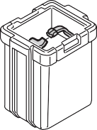
Check the battery as follows.
Make sure that the battery termi- nals are not corroded and that there are no loose connections, cracks, or loose clamps.
Terminals
Hold-down clamp
When recharging, the battery pro- duces hydrogen gas which is flam- mable and explosive. Therefore, observe the following precautions before recharging:
If the system will not start even after multiple attempts, contact your Toy- ota dealer.
443

Tires
Check if the treadwear indica- tors are showing on the tires. Also check the tires for uneven wear, such as excessive wear on one side of the tread.

 Check the spare tire condition and pressure if not rotated.
|
|
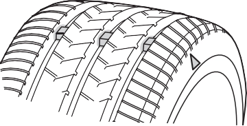
New tread Worn tread
Treadwear indicator
The location of treadwear indicators is shown by a “TWI” or “  ” mark,
etc., molded into the sidewall of each tire.
445
Replace the tires if the treadwear indicators are showing on a tire.
Tires should be replaced if:
If you are not sure, consult with your Toyota dealer.
Any tire over 6 years old must be checked by a qualified technician even if it has seldom or never been used or damage is not obvious.
Generally, low profile tires will wear more rapidly and tire grip perfor- mance will be reduced on snowy and/or icy roads when compared to standard tires. Be sure to use snow tires or tire chains on snowy and/or icy roads and drive carefully at a speed appropriate for road and weather conditions.
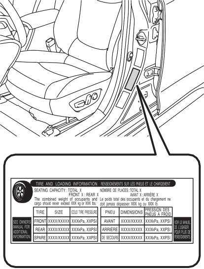
Check that the maximum load of the replacement tire is greater than 1/2 of the Gross Axle Weight Ratings (GAWR) of either the front axle or the rear axle, whichever is greater.
For the GAWR, see the Certification Label.
For the maximum load of the tire, see the load limit at maximum cold tire inflation pressure mentioned on the sidewall of the tire. (P.537)
Summer tires are high-speed perfor- mance tires best suited to highway driving under dry conditions. Since summer tires do not have the same traction performance as snow tires, summer tires are inadequate for driving on snow-covered or icy roads. For driving on snow-covered roads or icy roads, the use of snow tires is recommended. When install- ing snow tires, be sure to replace all four tires.
All season tires are designed to pro- vide better traction in snow and to be adequate for driving in most win- ter conditions as well as for use year-round. All season tires, how- ever, do not have adequate traction performance compared with snow tires in heavy or loose snow. Also, all season tires fall short in accelera- tion and handling performance com- pared with summer tires in highway driving.
For driving on snow-covered roads or icy roads, we recommend using snow tires. If you need snow tires, select tires of the same size, con- struction and load capacity as the originally installed tires. Since your vehicle has radial tires as original equipment, make sure your snow
tires also have radial construction. Do not install studded tires without first checking local regulations for possible restrictions. Snow tires should be installed on all wheels. (P.255)
The effectiveness of the tires as snow tires is lost.
When replacing the tires, check the tire valves for deformation, cracks, and other damage.
447
To equalize tire wear and extend tire life, Toyota recommends that tire rotation is carried out at the same interval as tire inspection.
Vehicles with a tire pressure warn- ing system: Do not fail to initialize the tire pressure warning system after tire rotation.
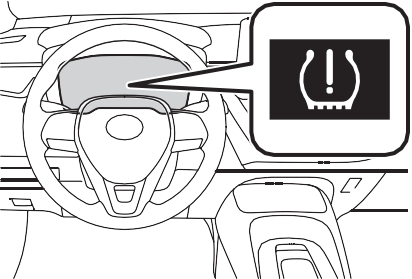
If the tire pressure drops below a predetermined level, the driver is warned by a warning light. (P.485)
The tire pressure warning system does not replace routine tire inflation pressure checks. Make sure to check tire inflation pressure as part of your routine of daily vehicle checks.
The warning of the tire pressure warning system will change in accordance with driving conditions. For this reason, the system may
give a warning even if the tire pres- sure does not reach a low enough level, or if the pressure is higher than the pressure that was adjusted to when the system was initialized.
Except for vehicles sold in Canada

For vehicles sold in Canada
449
When new tire pressure warning valves and transmitters are installed, new ID codes must be registered in the tire pressure warning computer and the tire pressure warning system must be initialized. Have tire pressure warning valves and transmitter ID codes registered by your Toy- ota dealer. (P.451)
If the ID code of the tire pressure warning valve and transmitter is not registered, the tire pressure warning system will not work properly. After driving for about 20 minutes, the tire pressure warning light blinks for 1 minute and stays on to indicate a system malfunction.
|
|
|
Repairing or replacing tires, wheels, tire pressure warn- ing valves, transmitters and tire valve caps
When removing or fitting the wheels, tires or the tire pressure warning valves and transmit- ters, contact your Toyota dealer as the tire pressure warning valves and transmitters may be damaged if not handled cor- rectly.
|
 NOTICE
registered wheel sets.
 When the tire pressure warning system is initialized, the current tire inflation pressure is set as the benchmark pressure.
Initialization cannot be performed while the vehicle is moving.
Make sure to adjust the tire pres- sure to the specified cold tire infla- tion pressure level. The tire pressure warning system will oper- ate based on this pressure level.
 Press
Press  or
or  of the meter control switch to select .
system must be initialized in the following circum- stances:


 press and hold .


 Press or to select “TPWS” and then press .
 Press or to select “Set Pressure”. Then press and
 hold until the tire pres-
451
|
|
Also, make sure the tires are cold before carrying out initialization or tire inflation pressure adjustment.
Initialization can be completed in a few minutes. However, in the follow- ing cases, the settings have not been recorded and the system will not operate properly. If repeated attempts to record tire inflation pres- sure settings are unsuccessful, have the vehicle inspected by your Toyota dealer.
|
|
|
When initializing the tire pres- sure warning system
Do not initialize the tire pressure warning system without first adjusting the tire inflation pres- sure to the specified level. Other- wise, the tire pressure warning light may not come on even if the tire inflation pressure is low, or it may come on when the tire infla- tion pressure is actually normal. |
 WARNING
Your vehicle is equipped with tire pressure warning system with the function to have ID codes registered for a second wheel set, for example a winter set, by Toyota dealer.
After registration of a second wheel set, either of these two wheel sets can be selected for usage with the tire pressure warning system.
 or
or  of the meter control switch to select
  .
.
 Press or to select “Vehicle Settings” and then
 press .


 Press or to select “TPWS” and then press .
 Press or to select “Change Wheel”. Then press
 and hold until the tire
pressure warning light blinks slowly 3 times.
|
|

7-3. Do-it-yourself maintenance
453
|
|
|
|
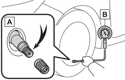
Tire valve
Tire pressure gauge
If you add too much air, press the center of the valve to deflate.
You should check tire inflation pres- sure every two weeks, or at least once a month. Do not forget to check the spare.
Driving with incorrect tire inflation pressure may result in the following:
If a tire needs frequent inflating, have it checked by your Toyota dealer.
When checking tire inflation pres- sure, observe the following:
If your vehicle has been parked for 
at least 3 hours or has not been driven for more than 1 mile or 1.5 km, you will get an accurate cold tire inflation pressure reading.
Passengers and luggage weight should be placed so that the vehi- cle is balanced.
|
|
|
Proper inflation is critical to save tire performance
Keep your tires properly inflated. If the tires are not properly inflated, the following conditions may occur which could lead to an accident resulting in death or seri- ous injury: Excessive wear
Uneven wear
Poor handling
Possibility of blowouts resulting from overheated tires
Air leaking from between tire and wheel
Wheel deformation and/or tire damage
|
 WARNING
Wheels
455
Replacement wheels are avail- able at your Toyota dealer.
*: Conventionally referred to as off- set.
The wheels of your vehicle are equipped with tire pressure warning valves and transmitters that allow the tire pressure warning system to provide advance warning in the event of a loss in tire inflation pres- sure. Whenever wheels are replaced, the tire pressure warning valves and transmitters must be installed. (P.449)
aluminum wheels when using tire chains.
|
|
|
Replacing tire pressure warn- ing valves and transmitters (vehicles with a tire pressure warning system)
Because tire repair or replace- ment may affect the tire pres- sure warning valves and transmitters, make sure to have tires serviced by your Toyota dealer or other qualified service shop. In addition, make sure to purchase your tire pressure warning valves and transmit- ters at your Toyota dealer.
Ensure that only genuine Toyota wheels are used on your vehi- cle.
Tire pressure warning valves and transmitters may not work properly with non-genuine wheels. |
 NOTICE
7-3. Do-it-yourself maintenance
457
filter cover.
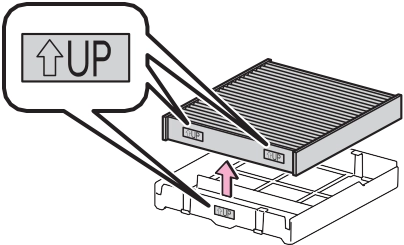
The “ UP” marks shown on the filter and the filter case should be pointing up.
|
|
Replace the air conditioning filter according to the maintenance schedule. In dusty areas or areas with heavy traffic flow, early replace-
ment may be required. (For sched- uled maintenance information, please refer to the “Scheduled Maintenance Guide” or “Owner’s Manual Supplement”.)
The filter may be clogged. Check the filter and replace if necessary.
|
|
|
When using the air condition- ing system
Make sure that a filter is always installed. Using the air conditioning system without a filter may cause damage to the system. To prevent damage to the fil- ter cover
When moving the filter cover in the direction of arrow to release the fitting, pay attention not to apply excessive force to the claws. Otherwise, the claws may be damaged. |
 NOTICE
*: If equipped
The following symptoms may occur:
minal facing up.
459
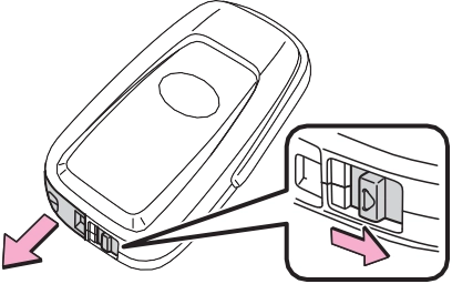
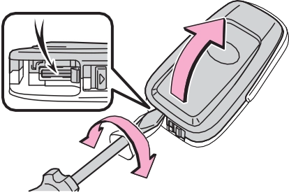
To prevent damage to the key, cover the tip of the flathead screw- driver with a rag.
|
|
If the battery cover is difficult to remove, lift the edge to remove it.
|
|
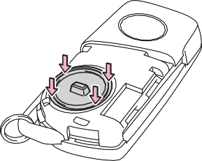
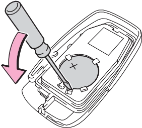
Insert a new battery with the “+” ter-
Push the entire edge of the battery cover into the key.
|
|
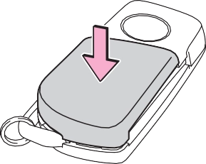
Align the key cover with the key and then press it straight into the key.
Make sure that the key cover is securely installed without any gaps between it and the key.
|
|
 or
or  switch and check that the doors can be locked/unlocked.
Vehicles with a smart key sys- tem
|
|
To prevent damage to the key, cover the tip of the flathead screw- driver with a rag.
|
|
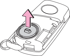
When removing the cover, the elec- tronic key module may stick to the cover and the battery may not be visible. In this case, remove the electronic key module in order to remove the battery.
Insert a new battery with the “+” ter-
minal facing up.
|
|
 or
or  switch and check that the doors can be locked/unlocked.
|
|
|
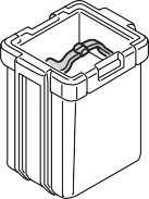
Removed battery and other parts
These parts are small and if swal- lowed by a child, they can cause choking. Keep away from chil- dren. Failure to do so could result in death or serious injury. |
 WARNING
461
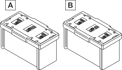
Engine compartment: type A fuse box
Push the tabs in and lift the lid off.
Push the tabs in and lift the lid off.
Under the driver’s side instru- ment panel
Remove the lid.
Make sure to push the claw when removing/installing the lid.
Only type A fuse can be removed using the pullout tool.
Replace the blown fuse with a new fuse of an appropriate amperage rating. The amperage rating can be found on the fuse box lid.
Type A
|
|
Type B
|
|
Type C
|
|
Type D
463
|
|
Type E
|
|
The fuses are designed to blow, pro- tecting the wiring harness from damage.
Toyota recommends that you use genuine Toyota products designed for this vehicle.
Because certain bulbs are con- nected to circuits designed to pre- vent overload, non-genuine parts of parts not designed for this vehicle may be unusable.
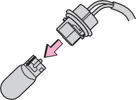
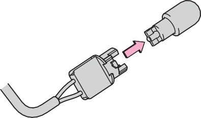
Light bulbs
Check the wattage of the light bulb to be replaced. (P.533)
|
|
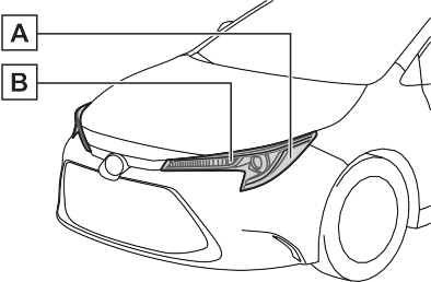
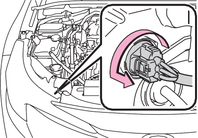
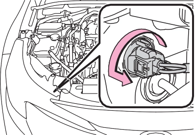
Front side marker lights
Front turn signal/parking lights (vehicles without side turn signal lights)
|
|
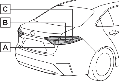
Back-up lights
Rear turn signal lights
Rear side marker lights (bulb type)
7-3. Do-it-yourself maintenance
Type A
465
The lights other than the front turn signal lights/parking lights (vehicles without side turn signal lights), front side marker lights, rear turn signal lights, rear side marker lights (bulb type) and back-up lights consist of a number of LEDs. If any of the LEDs burn out, take your vehicle to your Toyota dealer to have the light replaced.
In certain situations, such as when driving in the rain or when washing the vehicle, condensation may form on the inner side of the headlight lens and other lights. As each light has a ventilation hole, moist air may enter. If the ambient temperature is low, condensation may form tempo- rarily, but it will dissipate as the inside of the light is warmed up. As the condensation is due to a phe- nomenon similar to windows fogging in the rain, it does not indicate a malfunction.
Contact your Toyota dealer for more information in the following situa- tions:
P.463
|
|
Type B
|
|
Type A
|
|
Type B
To prevent scratching the vehicle, wrap the tip of the flathead screw- driver with a cloth, etc.
|
|
467
Rear side marker lights Rear turn signal lights
6 and 5 with the directions reversed.
Align the guide  and pin
  on the light assembly with the mount- ing when installing it.
To prevent scratching the vehicle, wrap the tip of the flathead screw- driver with a cloth, etc.
7 When installing the light bulb, install it by conducting steps
|
|
Align the guide  and pin
  on the light assembly with the mount- ing when installing it.
469
|
|
When trouble arises 8
471
Fuel pump shut off system
.................................. 480
If a warning light turns on or a warning buzzer sounds
.................................. 481
If a warning message is dis- played. 490
If you have a flat tire (vehi- cles without spare tire)
.................................. 493
If you have a flat tire (vehi- cles with a spare tire)
.................................. 503
If the engine will not start
.................................. 511
If you lose your keys 513
If the electronic key does not operate properly 513
If the vehicle battery is dis- charged 515
If your vehicle overheats
.................................. 519
If the vehicle becomes stuck
.................................. 521
8
Download Manual