Steps to take in an emergency
475
|
While towing
When towing using cables or chains, avoid sudden starts, etc. which place excessive stress on the towing eyelets, cables or chains. The towing eyelets, cables or chains may become damaged, broken debris may hit people, and cause serious dam- age.
Do not turn the engine switch off.
There is a possibility that the steering wheel is locked and cannot be operated. Installing towing eyelets to the vehicle
Make sure that towing eyelets are installed securely. If not securely installed, towing eyelets may come loose during towing. |

8
476 8-2. Steps to take in an emergency
From the front
The following may indicate a problem with your transmission. Contact your Toyota dealer or commercial towing service before towing.
Do not tow with a sling-type truck to prevent body damage.
Release the parking brake.
From the rear
|
|
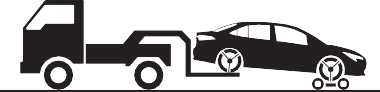
Use a towing dolly under the front wheels.
If your vehicle is transported by a flatbed truck, it should be tied down at the locations shown in the illustration.
8-2. Steps to take in an emergency
be in good condition.
477
If you use chains or cables to tie down your vehicle, the angles shaded in black must be 45°.
Do not overly tighten the tie downs or the vehicle may be damaged.
If a tow truck is not available in an emergency, your vehicle may be temporarily towed using cables or chains secured to the emergency towing eyelets. This should only be attempted on hard surfaced roads for at most 50 miles (80 km) at under 18
mph (30 km/h).
A driver must be in the vehicle to steer and operate the brakes.
The vehicle’s wheels, drive train, axles, steering and brakes must
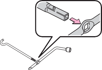
To protect the bodywork, place a rag between the screwdriver and the vehicle body as shown in the illustration.
2.0 L 4-cylinder (M20A-FKS) engine
Take care not to damage the vehi- cle body.
If the engine does not start, turn the engine switch to ON.
If the engine is not running, the power assist for the brakes and steering will not function, making steering and braking more difficult.
Wheel nut wrench is installed in trunk. (P.504)
side when braking
479
cornering
Follow the procedure below to restart the engine after the sys- tem is activated.
|
|
|
Before starting the engine
Inspect the ground under the vehicle. If you find that fuel has leaked onto the ground, the fuel system has been damaged and is in need of repair. Do not restart the engine. |
 NOTICE
8-2. Steps to take in an emergency
481
|
Warning light |
Details/Actions |
|
(U.S.A.) or |
Indicates that: The brake fluid level is low; or
The brake system is malfunctioning
|
|
(Red) (Canada) |
Immediately stop the vehicle in a safe place and con- tact your Toyota dealer. Continuing to drive the vehi- cle may be dangerous. |
8
|
Warning light |
Details/Actions |
|
Indicates that the engine coolant temperature is exces- sively high Immediately stop the vehicle in a safe place. Handling method (P.519) |
*: This light illuminates on the multi-information display.
|
Warning light |
Details/Actions |
|
Indicates a malfunction in the vehicle’s charging system Immediately stop the vehicle in a safe place and con- tact your Toyota dealer. |
|
Warning light |
Details/Actions |
|
Indicates that the engine oil pressure is excessively low Immediately stop the vehicle in a safe place and con- tact your Toyota dealer. |
*: This light illuminates on the multi-information display.
|
Warning light |
Details/Actions |
|
(U.S.A.) or (Canada) |
Indicates a malfunction in: The electronic engine control system;
The electronic throttle control system; or
The electronic continuously variable transmission (if equipped) control system
Immediately stop the vehicle in a safe place and con- tact your Toyota dealer. |
|
Warning light |
Details/Actions |
|
Indicates a malfunction in: The SRS airbag system;
The front passenger occupant classification system; or
The seat belt pretensioner system
Have the vehicle inspected by your Toyota dealer immediately. |
|
Warning light |
Details/Actions |
|
(U.S.A.) or (Canada) |
Indicates a malfunction in: The ABS; or
The brake assist system
Have the vehicle inspected by your Toyota dealer immediately. |
|
Warning light |
Details/Actions |
|
When a buzzer sounds: Indicates a malfunction in: The Brake Override System; or
The Drive-Start Control (if equipped)
Have the vehicle inspected by your Toyota dealer immediately. Indicates that the shift position was changed and Drive-Start Control (if equipped) was operated while depressing the accelerator pedal. Momentarily release the accelerator pedal. When a buzzer does not sound: Indicates that the accelerator and brake pedals are being depressed simultaneously, and the Brake Override System is operating. Release the accelerator pedal and depress the brake pedal. |
*: This light illuminates on the multi-information display.
|
Warning light |
Details/Actions |
|
(Red) or (Yellow) |
Indicates a malfunction in the EPS (Electric Power Steer- ing) system Have the vehicle inspected by your Toyota dealer immediately. |
|
Warning light |
Details/Actions |
|
Indicates that remaining fuel is approximately 2 gal. (7.5 L, 1.6 Imp. gal.) or less Refuel the vehicle. |
|
Warning light |
Details/Actions |
|
Warns the driver and/or front passenger to fasten their seat belts Fasten the seat belt. If the front passenger’s seat is occupied, the front passenger’s seat belt also needs to be fastened to make the warning light (warning buzzer) turn off. |
*: Driver’s seat belt warning buzzer:
The driver’s seat belt warning buzzer sounds to alert the driver that his or her seat belt is not fastened. Once the engine switch is turned to ON, the buzzer sounds for 6 seconds. If the vehicle reaches a speed of 12 mph (20 km/h), the buzzer sounds once. If the seat belt is still unfastened after 24 seconds, the buzzer will sound intermittently for 6 seconds. Then, if the seat belt is still unfastened, the buzzer will sound in a different tone for 90 more seconds.
Front passenger’s seat belt warning buzzer:
The front passenger’s seat belt warning buzzer sounds to alert the front passenger that his or her seat belt is not fastened. The buzzer sounds once if the vehicle reaches a speed of 12 mph (20 km/h). If the seat belt is still unfastened after 24 seconds, the buzzer will sound intermittently for 6 sec-
485
onds. Then, if the seat belt is still unfastened, the buzzer will sound in a dif- ferent tone for 90 more seconds.
|
Warning light |
Details/Actions |
|
|
Warns the rear passengers to fasten their seat belts Fasten the seat belt. |

*: Rear passengers’ seat belt warning buzzer:
The rear passengers’ seat belt warning buzzer sounds to alert the rear pas- sengers that his or her seat belt is not fastened. If any rear seat belt is fas- tened and then unfastened, the rear passengers' seat belt reminder light will illuminate for that seat. While illuminated, if the vehicle reaches a speed of 12 mph (20 km/h), the buzzer will sound once. If the seat belt is still unfastened after 24 seconds, the buzzer will sound intermittently for 6 sec- onds. Then, if the seat belt is still unfastened, the buzzer will sound in a dif- ferent tone for 30 more seconds.
|
Warning light |
Details/Actions |
|
(if equipped) |
When the light comes on after blinking for approximately 1 minute: Malfunction in the tire pressure warning system Have the system checked by your Toyota dealer. When the light comes on: Low tire inflation pressure such as Natural causes
Flat tire
Immediately stop the vehicle in a safe place. Handling method (P.488) |
|
Warning light |
Details/Actions |
|
(Orange) |
Indicates a malfunction in the LTA (Lane Tracing Assist) or LDA (Lane Departure Alert with steering control) Follow the instructions displayed on the multi-infor- mation display. (P.204, 212) |
|
Warning light |
Details/Actions |
|
(Flashes or illu- minates) |
When a buzzer sounds simultaneously: Indicates a malfunction has occurred in the PCS (Pre-Colli- sion System). Have the vehicle inspected by your Toyota dealer immediately. If a buzzer does not sound: The PCS (Pre-Collision System) has become temporarily unavailable, corrective action may be necessary. Follow the instructions displayed on the multi-infor- mation display. (P.185) If the PCS (Pre-Collision System) or VSC (Vehicle Stability Control) system is disabled, the PCS warning light will illu- minate. P.194 |
|
Warning light |
Details/Actions |
|
Indicates a malfunction in: The VSC system;
The TRAC system; or
The hill-start assist control system
Have the vehicle inspected by your Toyota dealer immediately. |
|
Warning light |
Details/Actions |
|
(Flashes) (U.S.A.) or (Flashes) (Canada) |
It is possible that the parking brake is not fully engaged or released Operate the parking brake once again. This light comes on when the parking brake is not released. If the light turns off after the parking brake is fully released, the system is operating normally. |
8-2. Steps to take in an emergency
487
|
Warning light |
Details/Actions |
|
(Orange) (if equipped) |
Indicates a malfunction in the iMT Have the vehicle inspected by your Toyota dealer immediately. |
In some cases, the buzzer may not be heard due to being in a noisy location or audio sound.
illuminated, it will turn off approxi- mately 60 seconds after the door is closed.
This warning light system monitors the airbag sensor assembly, front impact sensors, side impact sensors (front door), side impact sensors (front), side impact sensors (rear), driver’s seat position sensor, driver’s seat belt buckle switch, front passenger occupant classification system (ECU and sensors), “AIR BAG ON” indicator light, “AIR BAG OFF” indicator light, seat belt pre- tensioners, airbags, interconnecting wiring and power sources. (P.29)
First check the following:
If it is, fill the fuel tank immediately.
The light will go off after several driving trips.
If the light does not go off even after several trips, contact your Toyota dealer as soon as possible.
When the battery charge becomes insufficient or the voltage temporar- ily drops, the electric power steering system warning light may come on and the warning buzzer may sound.
Inspect the tires to check if a tire is punctured.
If a tire is punctured: P.493, 503
If none of the tires are punctured: Turn the engine switch off then turn it to ON. Check if the tire pressure warning light comes on or blinks.
If the tire pressure warning light blinks for approximately 1 minute then stays on
There may be a malfunction in the tire pressure warning system. Have the vehicle inspected by your Toyota dealer immediately.
If the tire pressure warning light comes on
Vehicles with a compact spare tire: The compact spare tire is not equipped with a tire pressure warn- ing valve and transmitter. If a tire goes flat, the tire pressure warning light will not turn off even though the flat tire has been replaced with the spare tire. Replace the spare tire with the repaired tire and adjust the tire inflation pressure. The tire pres- sure warning light will go off after a few minutes.
P.447
level.
The tire pressure warning light may come on due to natural causes such as natural air leaks and tire inflation pressure changes caused by tem- perature. In this case, adjusting the tire inflation pressure will turn off the warning light (after a few minutes).
 The warning messages explained below may differ from the actual messages according to operation conditions and vehicle specifica- tions.
A buzzer may sound when a mes- sage is displayed.
The buzzer may not be audible if the vehicle is in a noisy location or if the audio system volume is high.
The engine oil level is low. Check
491
the level of the engine oil, and add if necessary.
This message may appear if the vehicle is stopped on a slope. Move the vehicle to a level surface and check to see if the message disap- pears.
This message is displayed if the engine is stopped while driving.
When steering wheel operations are heavier than usual, grip the steering wheel firmly and operate it using more force than usual.
Power was cut off due to the auto- matic power off function. Next time when starting the engine, increase the engine speed slightly and main- tain that level for approximately 5 minutes to recharge the battery.
The following systems may be mal- functioning. Have the vehicle inspected by your Toyota dealer immediately.
The following systems may be sus- pended until the problem shown in the message is resolved. (P.185, 481)
The dynamic radar cruise control with full-speed range system or dynamic radar cruise control system is suspended temporarily or until the problem shown in the message is resolved. (causes and coping meth- ods: P.185)
The dynamic radar cruise control with full-speed range system or dynamic radar cruise control system cannot be used temporarily. Use the system when it becomes available again.
Indicates that all maintenance according to the driven distance on
the maintenance schedule* should 8
be performed soon.
Comes on approximately 4500 miles (7200 km) after the message has been reset. If necessary, per- form maintenance. Please reset the message after the maintenance is performed. (P.428)
*: Refer to the separate “Scheduled Maintenance” or “Owner’s Man- ual Supplement” for the mainte- nance interval applicable to your vehicle.
Indicates that all maintenance is
required to correspond to the driven distance on the maintenance sched- ule*.
Comes on approximately 5000 miles (8000 km) after the message has been reset. (The indicator will not work properly unless the mes- sage has been reset.) Perform the necessary maintenance. Please reset the message after the mainte- nance is performed. (P.428)
*: Refer to the separate “Scheduled Maintenance” or “Owner’s Man- ual Supplement” for the mainte- nance interval applicable to your vehicle.
The system or part shown on the multi-information display is malfunc- tioning. Have the vehicle inspected by your Toyota dealer immediately.
493
tinuously variable transmis- sion) or N (manual transmission).
A tire should only be repaired with the emergency tire punc- ture repair kit if the damage is caused by a nail or screw pass- ing through the tire tread.
8
In the following cases, the tire can- not be repaired with the emergency tire puncture repair kit. Contact your Toyota dealer.
more
Bottle
|
|
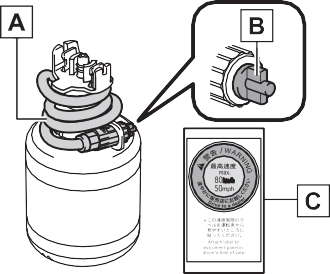
Air release cap
Sticker
495
|
|
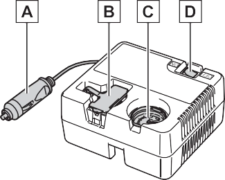
Power plug Rubber stopper
Air pressure gauge Compressor switch
Check the sealant expiry date occa- sionally.
The expiry date is shown on the bot- tle. Do not use sealant whose expiry date has already passed. Other- wise, repairs conducted using the emergency tire puncture repair kit may not be performed properly.
|
|
|
Caution while driving
Store the repair kit in the trunk. Injuries may result in the event of an accident or sudden brak- ing.
The repair kit is exclusively only for your vehicle.
Do not use repair kit on other vehicles, which could lead to an accident causing death or seri- ous injury. Do not use repair kit for tires that are different size than the original ones, or for any other purpose. If the tires have not been completely repaired, it could lead to an accident caus- ing death or serious injury.
|
 WARNING
Attach the sticker enclosed with the bottle on the specified locations. (See step 10.)
You will use the air release cap again. Therefore keep it in a safe place.
|
|
Screw the end of the hose clock- wise as far as possible.
|
|
|
|
497
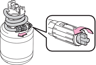
As shown in the illustration, insert the bottle securely into the com- pressor until the upper side of the mark on the bottle is aligned with
the upper end of the notch.
U.S.A.
Canada
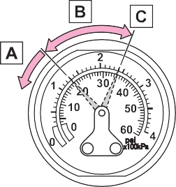
11Check the specified tire infla- tion pressure.
Tire inflation pressure is specified on the label on the driver’s side pil-
lar as shown. (P.531)
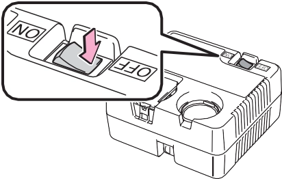
13To inject the sealant and inflate the tire, turn the com- pressor switch on.
14Inflate the tire until the speci- fied air pressure is reached.
|
|
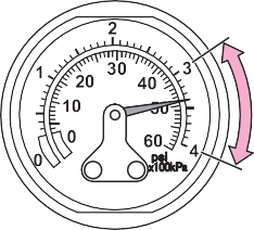
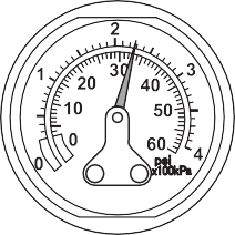
The sealant will be injected and the pressure will spike to between 44 psi (300 kPa, 3.0 kgf/cm2 or bar) and 58 psi (400 kPa, 4.0 kgf/cm2 or bar), then gradually decrease.
The air pressure gauge will display the actual tire inflation pressure about 1 to 5 min- utes after the switch is turned on.
Turn the compressor switch off and then check the tire inflation pres- sure. Being careful not to over inflate, check and repeat the infla- tion procedure until the specified tire inflation pressure is reached.
The tire can be inflated for about 5 to 20 minutes (depending on the outside temperature). If the tire inflation pressure is still lower than the specified point after inflation for 25 minutes, the tire is too damaged
499
to be repaired. Turn the compres- sor switch off and contact your Toy- ota dealer.
If the tire inflation pressure exceeds the specified air pressure, let out some air to adjust the tire inflation pressure. (P.500, 531)
Some sealant may leak when the hose is removed.
17Attach the air release cap to the end of the hose.
If the air release cap is not attached, the sealant may leak and the vehicle may get dirty.
19To spread the liquid sealant evenly within the tire, imme- diately drive safely for about 3 miles (5 km) below 50 mph
(80 km/h).
20After driving, stop your vehi- cle in a safe place on a hard,
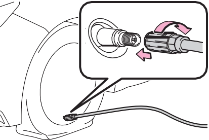
flat surface and reconnect the repair kit.
Remove the air release cap from the hose before reconnecting the hose.
|
|
If the tire inflation pressure is under 19 psi (130 kPa, 1.3 kgf/cm2 or bar): The puncture cannot be repaired. Contact your Toyota dealer.
If the tire inflation pressure is 19 psi (130 kPa, 1.3 kgf/cm2 or bar) or higher, but less
than the specified air pres- sure: Proceed to step 22.
If the tire inflation pressure is the specified air pressure (P.531): Proceed to step
23.
22Turn the compressor switch on to inflate the tire until the specified air pressure is reached. Drive for about 3 miles (5 km) and then per- form step 20.
23Attach the air release cap to the end of the hose.
If the air release cap is not attached, the sealant may leak and the vehicle may get dirty.
25Taking precautions to avoid sudden braking, sudden acceleration and sharp turns, drive carefully at under 50 mph (80 km/h) to the nearest Toyota dealer that is less than 62 miles (100 km) away for tire repair or replacement.
When having the tire repaired or replaced, make sure to tell the Toy- ota dealer that the sealant is injected.
1 Disconnect the hose from the valve.
If the air pressure is under the des- ignated pressure, turn the compres- sor switch on again and repeat the inflation procedure until the speci- fied air pressure is reached.
After a tire is repaired with the emer- gency tire puncture repair kit, the valve should be replaced.
8-2. Steps to take in an emergency
503
|
|
|
If you have a flat tire
Do not continue driving with a flat tire. Driving even a short distance with a flat tire can damage the tire and the wheel beyond repair, which could result in an accident. |
 WARNING
tinuously variable transmis- 8
sion) or R (manual transmission).
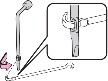
Wheel nut wrench Jack
Spare tire
Towing eyelet (if equipped)
|
|
|
Do not put any part of your body under the vehicle while it is sup- ported by the jack.
Do not start the engine or drive the vehicle while the vehicle is supported by the jack.
Do not raise the vehicle while someone is inside.
When raising the vehicle, do not put an object on or under the jack.
Do not raise the vehicle to a height greater than that required to replace the tire.
Use a jack stand if it is neces- sary to get under the vehicle.
When lowering the vehicle, make sure that there is no-one near the vehicle. If there are people nearby, warn them vocally before lowering.
|
 WARNING
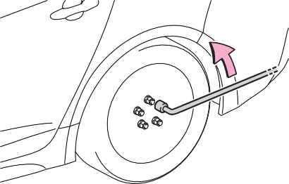
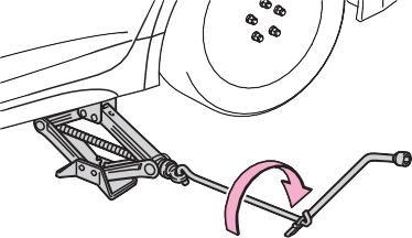
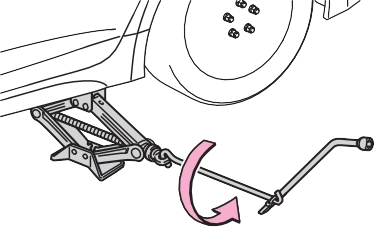
3 Loosen the center fastener that secures the spare tire.
 506 8-2. Steps to take in an emergency
place a rag between the wrench and the wheel ornament.
Insert the wrench into the notch on the wheel cap.
To protect the wheel ornament,
|
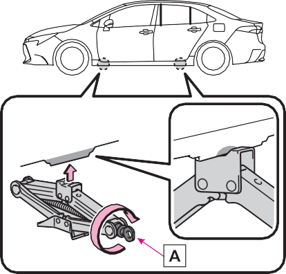
|
by hand until the center of the recessed portion of the jack is in contact with the center of the jack point.
|
|
|
|
|
|
|
|
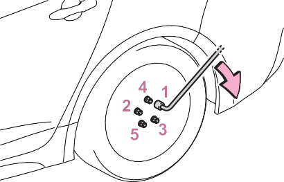
7 Remove all the wheel nuts and the tire.
When resting the tire on the ground, place the tire so that the wheel design faces up to avoid
wheel seat .
|
|
If foreign matter is on the wheel contact surface, the wheel nuts may loosen while the vehicle is in motion, causing the tire to come off.
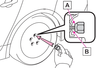
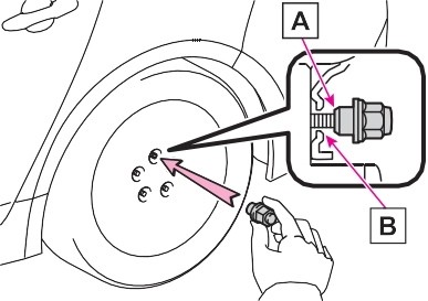
When replacing a steel wheel with a steel wheel (including a compact spare tire), tighten the wheel nuts
until the tapered portion  comes into loose contact with the disc
When replacing an aluminum wheel with a steel wheel (including a com- pact spare tire), tighten the wheel
nuts until the tapered portion  comes into loose contact with the
disc wheel seat .
|
|
|
|
Tightening torque:
509
76 ft•lbf (103 N•m, 10.5 kgf•m)
|
|
The vehicle becomes lower when driving with the compact spare tire compared to when driving with stan- dard tires.
The tire pressure warning system must be reset. (P.450)
As the compact spare tire is not equipped with a tire pressure warn- ing valve and transmitter, low infla- tion pressure of the spare tire will not be indicated by the tire pressure warning system. Also, if you replace the compact spare tire after the tire pressure warning light comes on, the light remains on.
Install the compact spare tire on one of the rear wheels of the vehicle.
Perform the following steps and fit tire chains to the front tires:
Align the cutout of the wheel orna- ment with the valve stem as shown in the illustration.
|
|
|
When using the compact spare tire
Remember that the compact spare tire provided is specifi- cally designed for use with your vehicle. Do not use your com- pact spare tire on another vehi- cle.
Do not use more than one com- pact spare tires simultaneously.
Replace the compact spare tire with a standard tire as soon as possible.
Avoid sudden acceleration, abrupt steering, sudden brak- ing and shifting operations that cause sudden engine braking.
|
 WARNING
8-2. Steps to take in an emergency
511
|
|
|
To avoid damage to the tire pressure warning valves and transmitters (vehicles with a tire pressure warning system)
When a tire is repaired with liquid sealants, the tire pressure warn- ing valve and transmitter may not operate properly. If a liquid seal- ant is used, contact your Toyota dealer or other qualified service shop as soon as possible. Make sure to replace the tire pressure warning valve and transmitter when replacing the tire. |
 NOTICE
tem. (P.67) 8
One of the following may be the cause of the problem:
The engine starting system may be malfunctioning due to an electrical problem such as elec- tronic key battery depletion or a blown fuse. However, an interim measure is available to start the engine. (P.512)
One of the following may be the cause of the problem:
Contact your Toyota dealer if the problem cannot be repaired, or if repair procedures are unknown.
Do not use this starting proce- dure except in case of emer- gency.
1 Set the parking brake. (P.163, 164)
2 Check that the shift lever is in P (continuously variable transmission) or N (manual transmission).
3 Turn the engine switch to ACC.
4 Press and hold the engine switch for about 15 seconds while depressing the brake pedal (continuously variable transmission) or clutch pedal (manual transmission) firmly.
Even if the engine can be started using the above steps, the system may be malfunctioning. Have the vehicle inspected by your Toyota dealer.
If you lose your keys
513
(P.113) 8
|
|
|
In case of a smart key system malfunction or other
key-related problems Take your vehicle with all the elec- tronic keys provided with your vehicle to your Toyota dealer. |
 NOTICE
following operations:
|
|
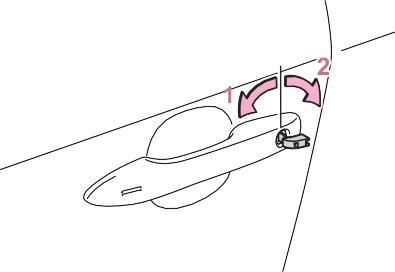
Turning the key unlocks the driver’s door. Turning the key again unlocks the other doors.
*1: If equipped
*2:This setting must be customized at your Toyota dealer.
Vehicles with a manual trans- mission: Shift the shift lever to N and depress the clutch pedal.
When the electronic key is detected, a buzzer sounds and the engine switch will turn to ON.
When the smart key system is deactivated in customization set- ting, the engine switch will turn to
ACC.
515
check that is shown on the multi-information display.
In the event that the engine still cannot be started, contact your Toyota dealer.
Shift the shift lever to P (continu- ously variable transmission) or N (manual transmission) and press the engine switch as you normally
do when stopping the engine. 8
As the above procedure is a tempo- rary measure, it is recommended that the electronic key battery be replaced immediately when the bat- tery is depleted. (P.458)
Release the brake pedal (continu- ously variable transmission) or clutch pedal (manual transmission) and press the engine switch in step 3 above.
The engine does not start and
modes will be changed each time the switch is pressed. (P.151)
When connecting the jumper (or booster) cables, depending on the
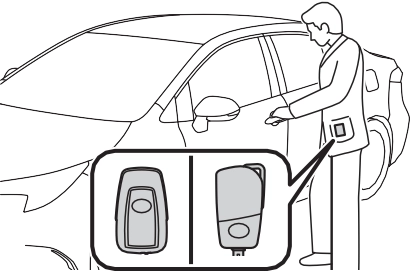
1 Vehicles with an alarm (P.69): Confirm that the electronic key (vehicles with a smart key system) or key (vehicles without a smart key system) is being carried.
situation, the alarm may activate and doors locked. (P.70)
|
|
on your vehicle and
connect the clamp on the other end of the positive cable to on the second vehicle. Then, connect a negative cable clamp to
on the second vehicle and connect the clamp at the other end of
the negative cable to .
1.8 L 4-cylinder (2ZR-FAE) engine
Positive (+) battery terminal (your vehicle) Positive (+) battery terminal (second vehicle) Negative (-) battery terminal (second vehicle)
Solid, stationary, unpainted metallic point away from the battery and any moving parts as shown in the illustration
2.0 L 4-cylinder (M20A-FKS) engine
517
Solid, stationary, unpainted metallic point away from the battery and any moving parts as shown in the illustration
reverse order from which they were connected.
Once the engine starts, have the vehicle inspected at your Toyota dealer as soon as possible.
The engine cannot be started by push-starting.
cleared. When the battery is depleted, have the vehicle inspected at your Toyota dealer.
When the battery terminals are removed, the information stored in the ECU is cleared. Before remov- ing the battery terminals, contact your Toyota dealer.
The electricity stored in the battery will discharge gradually even when the vehicle is not in use, due to nat- ural discharge and the draining effects of certain electrical appli- ances. If the vehicle is left for a long time, the battery may discharge, and the engine may be unable to start. (The battery recharges auto- matically during driving.)
|
|
|
When removing the battery terminals
Always remove the negative (-) terminal first. If the positive (+) ter- minal contacts any metal in the surrounding area when the posi- tive (+) terminal is removed, a spark may occur, leading to a fire in addition to electrical shocks and death or serious injury. Avoiding battery fires or explosions
Observe the following precautions to prevent accidentally igniting the flammable gas that may be emit- ted from the battery: Make sure each jumper cable is connected to the correct termi- nal and that it is not unintention- ally in contact with any other than the intended terminal.
Do not allow the other end of the jumper cable connected to the “+” terminal to come into contact with any other parts or metal surfaces in the area, such as brackets or unpainted metal.
|
 WARNING
519
If you do not see steam:  Carefully lift the hood.
hoses and radiator core (radi- ator) for any leaks.
Radiator Cooling fan
If a large amount of coolant leaks, immediately contact your Toyota dealer.
Reservoir
“FULL” line “LOW” line
Water can be used in an emer- gency if engine coolant is unavail-
able.
The fan operates when the air con- ditioning system is turned on imme- diately after a cold start. Confirm that the fan is operating by check- ing the fan sound and air flow. If it is difficult to check these, turn the air conditioning system on and off repeatedly. (The fan may not oper- ate in freezing temperatures.)
If the fan is operating: Have the vehicle inspected at the nearest Toyota dealer.
|
|
|
When inspecting under the hood of your vehicle
Observe the following precau- tions. Failure to do so may result in serious injury such as burns. |
 WARNING
521
 Remove the mud, snow or sand from around the front wheels.
Press the  switch to turn off TRAC.
|
|
|
When attempting to free a stuck vehicle
If you choose to push the vehicle back and forth to free it, make sure the surrounding area is clear to avoid striking other vehicles, objects or people. The vehicle may also lunge forward or lunge back suddenly as it becomes free. Use extreme caution. When shifting the shift lever
Be careful not to shift the shift lever with the accelerator pedal depressed. This may lead to unexpected rapid acceleration of the vehicle that may cause an accident resulting in death or serious injury. |
 WARNING
|
|
|
To avoid damaging the trans- mission and other compo- nents
Avoid spinning the front wheels and depressing the accelerator pedal more than necessary.
If the vehicle remains stuck even after these procedures are performed, the vehicle may require towing to be freed.
|
 NOTICE
523
Vehicle specifications 9
9-2. Customization
Customizable features
.................................. 548
9-3. Initialization
Items to initialize 556
9
Download Manual