Other interior features
Sun visors
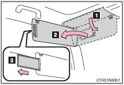
1. To set the visor in the forward position, flip it down.
2. To set the visor in the side position, flip down, unhook, and swing it to the side.
3. To use the side extender, place the visor in the side position, then slide it backward.
Vanity mirrors
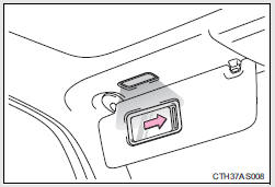
Slide the cover to open.
The light turns on when the cover is opened.
NOTICE
To prevent battery discharge
Do not leave the vanity lights on for extended periods while the engine is off.
Clock
1. Adjusts the hours
2. Adjusts the minutes
For quicker adjustment of the clock
To advance the minutes and hours quickly, press and hold the “M” or “H” button.
The time can be adjusted back or forth by following the procedure below:
The hour or minute can be moved forward or backward by pressing the “MODE/  ” or “SET/
 ” button while pressing and holding
the “H” or “M” button.
If the “MODE/  ” or “SET/
 ” button is also pressed and held in
the above operation, the hour or minute will move faster.
The clock is displayed when Vehicles without a smart key system
The engine switch is in the “ACC” or “ON” position.
Vehicles with a smart key system
The “ENGINE START STOP” switch is in ACCESSORY or IGNITION ON mode.
When disconnecting and reconnecting battery terminals
The clock data will be reset.
Outside temperature display
The temperature display shows temperatures within the ranges of -40°F (-40°C) and 122°F (50°C).
Vehicles without Multi-terrain Select
Vehicles with Multi-terrain Select
The outside temperature is displayed when
Vehicles without a smart key system
The engine switch is in the “ON” position.
Vehicles with a smart key system
The “ENGINE START STOP” switch is in IGNITION ON mode.
ICE indicator
Vehicles without Multi-terrain Select
If the outside temperature lowers to 37°F (3°C) or below when the engine switch is in the “ON” position (vehicles without a smart key system) or the “ENGINE START STOP” switch is in IGNITION ON mode (vehicles with a smart key system), the “ICE” indicator will come on to warn the driver that roads may be icy. Check the road surface and drive carefully. (The indicator will go off when the outside temperature rises to 41°F [5°C].)
Vehicles with Multi-terrain Select
If the outside temperature lowers to 37°F (3°C) or below when the engine switch is in the “ON” position, the “ICE” indicator will come on to warn the driver that roads may be icy. Check the road surface and drive carefully. (The indicator will go off when the outside temperature rises to 41°F [5°C].)
Display
In the following situations, the correct outside temperature may not be displayed, or the display may take longer than normal to change:
• When the vehicle is stopped, or moving at low speeds (less than 14 mph [24 km/h])
• When the outside temperature has changed suddenly (at the entrance/ exit of a garage, tunnel, etc.)
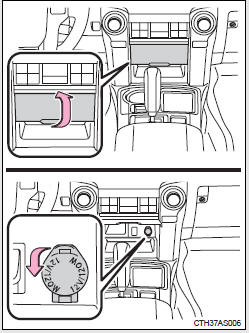
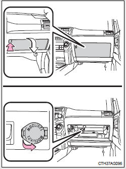
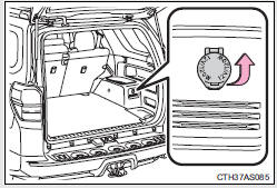
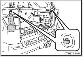
Power outlets (12 V DC)
The power outlet can be used for 12 V accessories that run on less than 10 A.
Center panel
Glove box
Luggage compartment (vehicles without the 120 V AC)
Luggage compartment (vehicles with the 120 V AC)
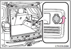
The power outlet can be used when
Vehicles without a smart key system
The engine switch is in the “ACC” or “ON” position.
Vehicles with a smart key system
The “ENGINE START STOP” switch is in ACCESSORY or IGNITION ON mode.
NOTICE
To avoid damaging the power outlet
Close the power outlet lid when the power outlet is not in use.
Foreign objects or liquids that enter the power outlet may cause a short circuit.
To prevent blown fuse
Do not use an accessory that uses more than 12 V 10 A.
To prevent battery discharge
Do not use the power outlet longer than necessary when the engine is not running.
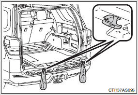
Power outlets (120 V AC)
The power outlet can be used for electrical appliances.
Main switch
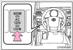
To use the power outlet, turn on the main switch.
The power supply starts a few seconds after the main switch is pressed.
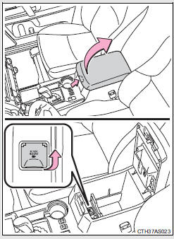
Power outlet socket (in the console box)
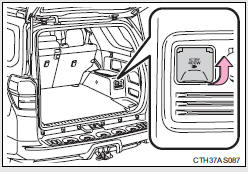
Power outlet socket (luggage compartment)
Maximum available capacity of the power outlet
While the vehicle is being driven
The maximum capacity of the power outlet is always 120 V AC/100 W.
When the vehicle is stationary
The maximum capacity of the power outlet varies depending on the position of the shift lever.
• The maximum capacity is 120 V AC/100 W when the shift lever is in any position other than P or N.
• The maximum capacity is 120 V AC/400 W when the shift lever is in P or N.
The maximum capacity of 400 W can only be restored by turning the power outlet main switch off and then on again with the shift lever in P or N.
The power outlet can be used when
The engine is running.
The indicator light changes according to the maximum available capacity as follows:
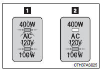
1. 120 V AC/400 W 2. 120 V AC/100 W
When the power outlet is in operation
The sound of the cooling fan may be heard from the right side of the luggage compartment. This is normal and does not indicate a malfunction.
If the engine is started with the power outlet main switch on
The maximum capacity of the power supply may decrease to below the standard, or may be cut off completely, even when the vehicle is stationary.
The protection circuit may be activated to cut the power supply if any of the following conditions apply:
• The engine is started with the power outlet main switch on.
• Use of electrical appliances exceeding the maximum capacity is attempted.
A sound may be heard when the protection circuit is activated. This is normal and does not indicate a malfunction.
• Electrical appliances, which consume power exceeding 100 W, have been used continuously for a long time period.
• The total power usage by all electrical features (headlights, air conditioning, etc.) has exceeded the total vehicle maximum for an extended period of time.
If the protection circuit is activated and the power supply is cut, conduct the following procedure:
 Park the vehicle in a safe place,
and then securely apply the parking brake.
 Check and ensure that the shift
lever is in P or N.
 Make sure that the power
consumption of the electric appliance is within the maximum capacity of the power outlet and the appliance is not broken.
 Press the power outlet main
switch again.
When the cabin temperature is high, open the windows to cool the temperature down. Once it reaches the normal temperature, turn the power outlet main switch on again.
If the power supply does not resume even after the above procedure has been performed, have the vehicle inspected by your Toyota dealer.
CAUTION
Using a power outlet
Observe the following precautions to reduce the risk of injury.
• Use of the power outlet when it is wet with water or snow may result in electrical shocks and is extremely dangerous. The power outlet must be thoroughly dried before use.
• Do not allow children to use or play with the power outlet.
• Be careful not to get any part of your body caught in the power outlet lid.
• When using electrical appliances, strictly follow any cautions and notices written on their labels and in the manufacturers' instruction manuals.
• Do not modify, disassemble or repair the power outlet or its inverter in any way. Doing so may result in unexpected malfunctions or accidents, which could cause serious damage or injuries. Contact your Toyota dealer for any necessary repairs.
To prevent injuries and accidents, secure all electric appliances before use and do not use any appliances that may do any of the following:
• Distract the driver while driving, or hamper safe driving.
• Result in a fire or burn injuries due to the appliance rolling, falling or overheating while driving.
• Emit steam while the windows of the cabin are closed.
To prevent unexpected accidents, such as electric shocks, do not perform any of the following actions:
• Using the power outlet for electric heaters while sleeping.
• Contaminating the power outlet with liquid substances or mud.
• Handling electrical appliance plugs at the power outlet with wet hands or feet.
• Inserting foreign objects into the power outlet.
• Using malfunctioning electric appliances.
• Inserting inappropriate or badly fitting plugs into the power outlet.
NOTICE
To avoid damaging the power outlet and the plug
• Close the power outlet lid when not in use.
• Do not allow foreign objects or liquids to enter the power outlet, as this may cause a short circuit.
• Do not use plug adaptors to connect too many plugs to the power outlet.
• After removing a plug, gently close the power outlet lid.
To prevent the fuse from being blown
Do not use a 120 V AC appliance that requires more than the maximum capacity of the power outlet. If a 120 V AC appliance that consumes more than the maximum capacity is used, the protection circuit will cut the power supply.
Appliances that may not operate properly (120 V AC)
The following 120 V AC appliances may not operate even if their power consumption is under maximum capacity.
• Appliances with high initial peak wattage • Measuring devices that process precise data.
• Other appliances that require an extremely stable power supply
To prevent battery discharge
Turn off all the vehicle's electronic equipment and accessories, such as the headlights and air conditioning, when electrical appliances that consume in excess of 100 W are used continuously for long periods of time.
To prevent any damage caused by heat
• Do not use any electrical appliances that give off intense heat, such as toasters, in any locations including the internal or external trim, seats and deck.
• Do not use any electrical appliances that are easily affected by vibration or heat inside the vehicle. Vibration while driving, or the heat of the sun while parking, may result in damage to those electrical appliances.
NOTICE
If any electrical appliances are to be used while driving
Securely fasten both the appliances and their cables to prevent them from falling or getting caught in any of the power train components.
If the power outlet is loose when an electrical appliance plug is connected
Replace the outlet. Contact your Toyota dealer for any necessary replacements.
If the power outlet gets dirty
Turn the main switch off and use a soft, clean cloth to wipe it gently. Do not use any cleansing materials, such as organic solvents, wax, or compound cleaners, as these may damage the power outlet or cause it to malfunction.
Seat heaters
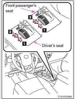
1. On The indicator light comes on.
2. Adjusts the seat temperature The further you move the dial forward, the warmer the seat becomes.
The seat heaters can be used when
Vehicles without a smart key system
The engine switch is in the “ON” position.
Vehicles with a smart key system
The “ENGINE START STOP” switch is in IGNITION ON mode.
When not in use
Move the dial fully backward. The indicator light turns off.
CAUTION
Burns
• Use caution when seating the following persons in a seat with the seat heater on to avoid the possibility of burns:
• Babies, small children, the elderly, the sick and the physically challenged
• Persons with sensitive skin
• Persons who are fatigued
• Persons who have taken alcohol or drugs that induce sleep (sleeping drugs, cold remedies, etc.)
• Do not cover the seat with anything when using the seat heater.
Using the seat heater with a blanket or cushion increases the temperature of the seat and may lead to overheating.
• Do not use the seat heater more than necessary. Doing so may cause minor burns or overheating.
NOTICE
To prevent seat heater damage
Do not put heavy objects that have an uneven surface on the seat and do not stick sharp objects (needles, nails, etc.) into the seat.
To prevent battery discharge
Turn the seat heaters off when the engine is not running.
Armrest
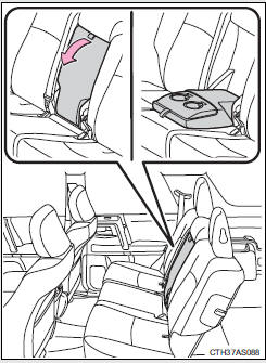
Fold down the armrest for use.
NOTICE
To prevent damage to the armrest
Do not apply too much load on the armrest.
Assist grips
An assist grip (type A) installed on the ceiling can be used to support your body while sitting on the seat.
An assist grip (type B) installed on the pillar can be used when getting in or out of the vehicle and others.
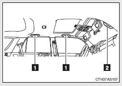
1. Assist grip (type A)
2. Assist grip (type B)
CAUTION
Assist grip (type A)
Do not use the assist grip (type A) when getting in or out of the vehicle or rising from your seat.
NOTICE
To prevent damage to the assist grip
Do not hang any heavy object or put a heavy load on the assist grip.
Floor mat
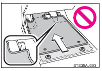
Use only floor mats designed specifically for vehicles of the same model and model year as your vehicle. Fix them securely in place onto the carpet.
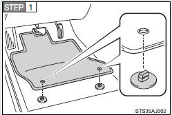
Insert the retaining hooks (clips) into the floor mat eyelets.
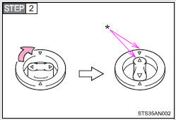
Turn the upper knob of each retaining hook (clip) to secure the floor mats in place.
*: Always align the Δ marks.
The shape of the retaining hooks (clips) may differ from that shown in the illustration.
CAUTION
Observe the following precautions.
Failure to do so may cause the driver's floor mat to slip, possibly interfering with the pedals while driving. An unexpectedly high speed may result or it may become difficult to stop the vehicle, leading to a serious accident which may result in death or serious injury.
When installing the driver's floor mat
• Do not use floor mats designed for other models or different model year vehicles, even if they are Toyota Genuine floor mats.
• Only use floor mats designed for the driver's seat.
• Always install the floor mat securely using the retaining hooks (clips) provided.
• Do not use two or more floor mats on top of each other.
• Do not place the floor mat bottom-side up or upside-down.
Before driving
• Check that the floor mat is securely fixed in the correct place with all the provided retaining hooks (clips). Be especially careful to perform this check after cleaning the floor.
• With the engine stopped and the shift lever in P, fully depress each pedal to the floor to make sure it does not interfere with the floor mat.
Compass
The compass on the accessory meter display indicates the direction in which the vehicle is heading.
1. “MODE/  ” button
2. “SET/  ” button
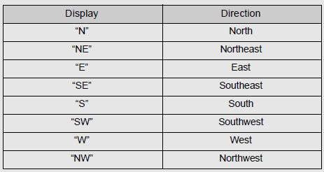
3. Direction display
Displays and directions
Calibrating the compass
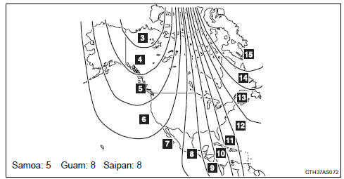
The direction display deviates from the true direction determined by the earth’s magnetic field. The amount of deviation varies depending on the geographic position of the vehicle.
If you cross over one of the map boundaries shown in illustration, the compass will deviate.
To obtain higher precision or perfect calibration, refer to “Deviation calibration”.
Deviation calibration
Stop the vehicle.
Change the accessory meter
display to deviation calibration mode by doing the following.
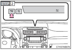
Vehicles without Multi-terrain Select
When the parking lights are turned on: Press and hold the “MODE/  ” button.
A number (1 to 15) will appear on the display.
When the parking lights are off:
In accessory meter light control mode , press and hold the “MODE/  ” button.
A number (1 to 15) will appear on the display.
Vehicles with Multi-terrain Select
When the parking lights are turned on:
Press and hold the “MODE/ ”
button.
A number (1 to 15) will appear on the display.
When the parking lights are off: In accessory meter light control mode , press and hold the “MODE/ ” button.
A number (1 to 15) will appear on the display.
Referring to the map above, press
the “MODE/ ” or “SET/
 ” button to select the number of the
zone you are in.
Press and hold the “SET/
 ” button to confirm the number and
to exit deviation calibration mode. (If the button is pressed for more than 6 seconds, the number will automatically be confirmed and the display returned to normal.)
Circling calibration
If “ •” appears on the left side of the direction display, circling calibration needs to be performed.
Stop the vehicle in a place where
it is safe to drive in a circle.
In deviation calibration mode , press and hold the “MODE/ ” button to change to circling
calibration mode.
“ •” on the left side of the direction display will blink.
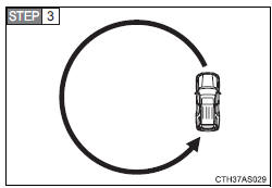
Drive the vehicle in a circle completing at least one full circle within 20 - 120 seconds.
If there is not enough space to drive in a circle, drive around the block until a direction is displayed.
Press and hold the “SET/
” button to confirm the direction
and to exit circling calibration mode. (If the button is pressed for several minutes, the direction will automatically be confirmed and the display returned to normal.)
 Make sure that “
•” on the left side of the direction display has gone off. If “ •” is illuminated, perform the above procedure again.
Conditions unfavorable to correct operation
The compass may not show the correct direction in the following conditions:
• The vehicle is stopped immediately after turning.
• The vehicle is on an inclined surface.
• The vehicle is in a place where the earth's magnetic field is subject to interference by artificial magnetic fields (underground car park/parking lot, under a steel tower, between buildings, roof car park/parking lot, near an intersection, near a large vehicle, etc.).
• The vehicle has become magnetized.
(There is a magnet or metal object near the accessory meter display.)
• The battery has been disconnected.
• A door is open.
Circling calibration error message (vehicles with Multi-terrain Select)
In the following situations, an error message regarding the circling calibration will appear on the accessory meter display for a few seconds:
• The vehicle was driven too fast during the circling calibration.
• The circling calibration was not completed successfully within about two minutes.
CAUTION
While driving the vehicle
Do not adjust the display. Adjust the display only when the vehicle is stopped.
When doing the circling calibration
Secure a wide space, and watch out for people and vehicles in the vicinity.
Do not violate any local traffic rules while performing circling calibration.
NOTICE
To avoid compass malfunctions
Do not place magnets or any metal objects near the accessory meter display.
Doing this may cause the compass sensor to malfunction.
To ensure normal operation of the compass
• Do not perform a circling calibration of the compass in a place where the earth's magnetic field is subject to interference by artificial magnetic fields.
• During calibration, do not operate electric systems (moon roof, power windows, etc.) as they may interfere with the calibration.
Luggage compartment features
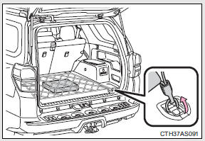
Cargo hooks
Vehicles with third seats
Fold down the third seats.
Raise the hook to use.
The cargo hooks are provided for securing loose items.
Vehicles without third seats
Raise the hook to use.
The cargo hooks are provided for securing loose items.
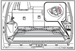
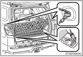
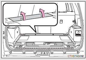
Cargo net hooks
The cargo net itself is not included as original equipment.
Vehicles with third seats (pattern 1)
Raise the rear cargo hook to use.
Vehicles with third seats (pattern 2)
 Fold down the third seats.
Raise the cargo hook to use.
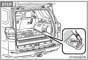
Vehicles without third seats (pattern 1)
Raise the rear cargo hook to use.
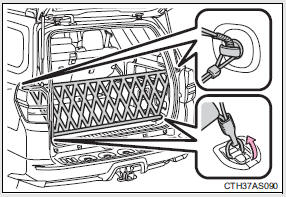
Vehicles without third seats (pattern 2)
Raise the cargo hook to use.
Storage compartment
Type A (if equipped)
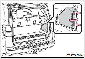
Open the storage compartment as shown.
Type B (if equipped)
Open the storage compartment as shown.
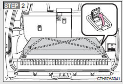
Slide deck (if equipped)
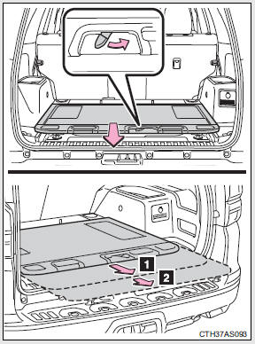
Slide the deck while turning the lock release lever, and then release the lever after sliding the deck to the lock position.
1. Half-slide locked position 2. Full-slide locked position
Grocery bag hooks
Type A
Type B (if equipped)
To use the grocery bag hooks, slide the slide deck to the fullslide locked position.
CAUTION
When the cargo hooks are not in use
To avoid injury, always return the cargo hooks to their stowed positions.
Slide deck operating precaution (if equipped)
• Be careful not to get hands or feet pinched by the slide deck.
• Be careful not to allow the slide deck to hit any persons or luggage while sliding the deck.
• Do not operate the slide deck while someone is on it.
Doing so may cause an accident.
• If operating the slide deck when the vehicle is stopped on an incline, the slide deck may move faster. Be careful not to allow the slide deck to hit you or pinch your fingers etc.
• After sliding the deck, make sure it is securely locked in position.
• Do not close the back door while any person is sitting on the slide deck or any person is between the slide deck and back door.
• Do not stow any objects into the space between the slide deck rails.
NOTICE
To prevent damage to the cargo net hooks
Avoid hanging things other than a cargo net on them.
Slide deck weight capacity (if equipped)
Do not load anything heavier than 440 lb. (200 kg) on the sliding deck.
Grocery bag hook weight capacity
Do not hang any object heavier than 8.8 lb. (4 kg) on the grocery bag hooks.
When using the slide deck (if equipped)
• Do not close the back door while the slide deck is sliding out. Doing so may cause the back door or slide deck to break.
• If operating the slide deck when the vehicle is stopped on an incline, the slide deck may move faster. Be careful as luggage may become damaged or fly out and damage the cabin.
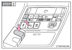
Garage door opener
The garage door opener can be programmed to operate garage doors, gates, entry doors, door locks, home lighting systems, security systems, and other devices.
The garage door opener (HomeLink® Universal Transceiver) is manufactured under license from HomeLink®.
Programming HomeLink® (for U.S. owners)
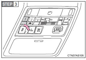
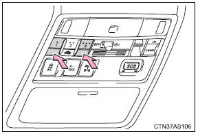
The HomeLink® compatible transceiver in your vehicle has 3 buttons which can be programmed to operate 3 different devices. Refer to the programming method below appropriate for the device.
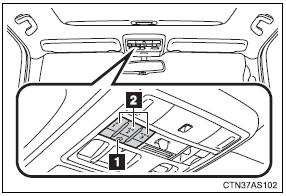
1. Indicator light
2. Buttons
Programming HomeLink®
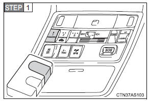
Point the remote control transmitter for the device 1 to 3 in. (25 to 75 mm) from the HomeLink® buttons.
Keep the HomeLink® indicator light in view while programming.
Press and hold one of the HomeLink® buttons and the transmitter button. When the HomeLink® indicator light changes from a slow to a rapid flash, you can release both buttons.
If the HomeLink® indicator light comes on but does not flash, or flashes rapidly for 2 seconds and remains lit, the HomeLink® button is already programmed. Use the other buttons or follow the “Reprogramming a HomeLink® button” instructions.
Test the HomeLink® operation by pressing the newly programmed button.
If a HomeLink® button has been programmed for a garage door, check to see if the garage door opens and closes. If the garage door does not operate, see if your garage transmitter is of the rolling code type. Press and hold the programmed HomeLink® button.
The remote control transmitter is of the rolling code type if the HomeLink® indicator light flashes rapidly for 2 seconds and then remains lit. If your transmitter is the rolling code type, proceed to the heading “Programming a rolling code system”.
 Repeat the steps above to
program another device for any of the remaining HomeLink® buttons.
Programming a rolling code system (for U.S. owners)
If your device is rolling code equipped, follow the steps under the heading “Programming HomeLink®” before proceeding with the steps listed below.
 Locate the training button* on
the ceiling mounted garage door opener motor. The exact location and color of the button may vary by brand of garage door opener.
Refer to the operation manual supplied with the garage door opener for the location of the training button*.
 Press the training button*.
Following this step, you have 30 seconds in which to initiate step 3 below.
 Press and hold the vehicle’s
programmed HomeLink® button for 2 seconds and release it. Repeat this step once again. The garage door may open.
If the garage door opens, the programming process is complete. If the door does not open, press and release the button a third time.
This third press and release will complete the programming process by opening the garage door.
The ceiling mounted garage door opener motor should now recognize the HomeLink® signal and operate the garage door.
Repeat the steps above to
program another rolling code system for any of the remaining HomeLink® buttons.
*: Names such as “learn”, “smart” or others vary according to manufacturer.
Programming an entry gate (for U.S. owners)/Programming a device in the Canadian market
Place the remote control
transmitter 1 to 3 in. (25 to 75 mm) away from the HomeLink® buttons.
Keep the HomeLink® indicator light in view while programming.
Press and hold the selected
HomeLink® button.
Repeatedly press and release
(cycle) the remote control transmitter for 2 seconds each until step 4 is completed.
When the HomeLink® indicator
light starts to flash rapidly, release the buttons.
 Test the HomeLink® operation by
pressing the newly programmed button. Check to see if the gate/device operates correctly.
 Repeat the steps above to
program another device for any of the remaining HomeLink® buttons.
Programming other devices
To program other devices such as home security systems, home door locks and lighting, contact your Toyota dealer for assistance.
Reprogramming a button
The individual HomeLink® buttons cannot be erased but can be reprogrammed. To reprogram a button, follow the “Reprogramming a HomeLink® button” instructions.
Operating HomeLink®
Press the appropriate HomeLink® button. The HomeLink® indicator light should come on.
The HomeLink® compatible transceiver in your vehicle continues to send a signal for up to 20 seconds as long as the button is pressed.
Reprogramming a HomeLink® button
Press and hold the desired HomeLink® button. After 20 seconds, the HomeLink® indicator light will start flashing slowly. Keep pressing the HomeLink® button and press and hold the transmitter button until the HomeLink® indicator light changes from a slow to a rapid flash.
Release the buttons.
Erasing the entire HomeLink® memory (all three programs)
Press and hold the 2 outside buttons for 10 seconds until the indicator light flashes.
If you sell your vehicle, be sure to erase the programs stored in the HomeLink® memory.
Before programming
• Install a new battery in the remote control transmitter.
• The battery side of the remote control transmitter must be pointed away from the HomeLink® button.
When programming
Depending on radio wave conditions, the direction the remote control transmitter is pointed and the remaining charge of the transmitter's batteries, there are cases when programming may be difficult.
Certification for the garage door opener For vehicles sold in the U.S.A.
FCC ID: CB2610HL4
NOTE:
This device complies with Part 15 of the FCC Rules. Operation is subject to the following two conditions: (1) this device may not cause harmful interference, and (2) this device must accept any interference received, including interference that may cause undesired operation.
FCC WARNING:
Changes or modifications not expressly approved by the party responsible for compliance could void the user's authority to operate the equipment.
For vehicles sold in Canada
NOTE:
Operation is subject to the following two conditions: (1) this device may not cause interference, and (2) this device must accept any interference, including interference that may cause undesired operation of the device.
When support is necessary
Visit on the web at www.homelink.com or call 1-800-355-3515.
CAUTION
When programming a garage door or other remote control devices
The garage door or other devices may operate, so ensure people and objects are out of danger to prevent potential harm.
Conforming to federal safety standards
Do not use the HomeLink® compatible transceiver with any garage door opener or device that lacks safety stop and reverse features as required by federal safety standards.
This includes any garage door that cannot detect an interfering object. A door or device without these features increases the risk of death or serious injury.
Safety Connect
Safety Connect is a subscription-based telematics service that uses Global Positioning System (GPS) data and embedded cellular technology to provide safety and security features to subscribers. Safety Connect is supported by Toyota’s designated response center, which operates 24 hours per day, 7 days per week.
Safety Connect service is available by subscription on select, telematics hardware-equipped vehicles.
By using the Safety Connect service, you are agreeing to be bound by the Telematics Subscription Service Agreement and its Terms and Conditions, as in effect and amended from time to time, a current copy of which is available at Toyota.com. All use of the Safety Connect service is subject to such then-applicable Terms and Conditions.
System components
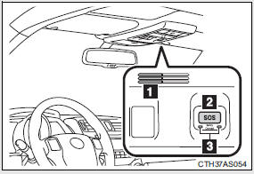
1. Microphone
2. “SOS” button
3. LED light indicators
Services Subscribers have the following Safety Connect services available:
• Automatic Collision Notification* Helps drivers receive necessary response from emergency service providers.
*: U.S. Patent No. 7,508,298 B2 • Stolen Vehicle Location Helps drivers in the event of vehicle theft. • Emergency Assistance Button (“SOS”) Connects drivers to response-center support.
• Enhanced Roadside Assistance Provides drivers various on-road assistance.
Subscription After you have signed the Telematics Subscription Service Agreement and are enrolled, you can begin receiving services.
A variety of subscription terms is available for purchase. Contact your Toyota dealer, call 1-800-331-4331, or push the “SOS” button in your vehicle for further subscription details.
Safety Connect Services Information
• Phone calls using the vehicles Bluetooth® technology will not be possible during Safety Connect.
• Safety Connect is available beginning Fall 2009 on select Toyota models.
Contact with the Safety Connect response center is dependent upon the telematics device being in operative condition, cellular connection availability, and GPS satellite signal reception, which can limit the ability to reach the response center or receive emergency service support. Enrollment and Telematics Subscription Service Agreement required. A variety of subscription terms is available; charges vary by subscription term selected.
• Automatic Collision Notification, Emergency Assistance, Stolen Vehicle Location, and Enhanced Roadside Assistance will function in the United States, including Hawaii and Alaska, and in Canada. No Safety Connect services will function outside of the United States in countries other than Canada.
• Safety Connect services are not subject to section 255 of the Telecommunications Act and the device is not TTY compatible.
Languages
The Safety Connect response center will offer support in multiple languages.
The Safety Connect system will offer voice prompts in English and Spanish.
Please indicate your language of choice when enrolling.
When contacting the response center
You may be unable to contact the response center if the network is busy.
Safety Connect LED light Indicators
When the “ENGINE START STOP” switch is turned to IGNITION ON mode (vehicles with a smart key system) or the engine switch is turned to the “ON” position (vehicles without a smart key system), the red indicator light comes on for 2 seconds then turns off. Afterward, the green indicator light comes on, indicating that the service is active.
The following indicator light patterns indicate specific system usage conditions:
• Green indicator light on = Active service • Green indicator light flashing = Safety Connect call in process • Red indicator light (except at vehicle start-up) = System malfunction (contact your Toyota dealer)
• No indicator light (off) = Safety Connect service not active
Safety Connect services
Automatic Collision Notification In case of either airbag deployment or severe rear-end collision, the system is designed to automatically call the response center.
The responding agent receives the vehicle’s location and attempts to speak with the vehicle occupants to assess the level of emergency.
If the occupants are unable to communicate, the agent automatically treats the call as an emergency, contacts the nearest emergency services provider to describe the situation, and requests that assistance be sent to the location.
Stolen Vehicle Location If your vehicle is stolen, Safety Connect can work with local authorities to assist them in locating and recovering the vehicle. After filing a police report, call the Safety Connect response center at 1- 800-331-4331 and follow the prompts for Safety Connect to initiate this service.
In addition to assisting law enforcement with recovery of a stolen vehicle, Safety-Connect-equipped vehicle location data may, under certain circumstances, be shared with third parties to locate your vehicle. Further information is available at Toyota.com.
Emergency Assistance Button (“SOS”) In the event of an emergency on the road, push the “SOS” button to reach the Safety Connect response center. The answering agent will determine your vehicle’s location, assess the emergency, and dispatch the necessary assistance required.
If you accidentally press the “SOS” button, tell the response-center agent that you are not experiencing an emergency.
Enhanced Roadside Assistance Enhanced Roadside Assistance adds GPS data to the already included warranty-based Toyota roadside service.
Subscribers can press the “SOS” button to reach a Safety Connect response-center agent, who can help with a wide range of needs, such as: towing, flat tire, fuel delivery, etc. For a description of the Enhanced Roadside Assistance services and their limitations, please see the Safety Connect Terms and Conditions, which are available at Toyota.com.
Safety information for Safety Connect
Important! Read this information before using Safety Connect.
Exposure to radio frequency signals
The Safety Connect system installed in your vehicle is a low-power radio transmitter and receiver. It receives and also sends out radio frequency (RF) signals.
In August 1996, the Federal Communications Commission (FCC) adopted RF exposure guidelines with safety levels for mobile wireless phones. Those guidelines are consistent with the safety standards previously set by the following U.S. and international standards bodies.
• ANSI (American National Standards Institute) C95.1 [1992] • NCRP (National Council on Radiation Protection and Measurement) Report 86 [1986]
• ICNIRP (International Commission on Non-Ionizing Radiation Protection) [1996] Those standards were based on comprehensive and periodic evaluations of the relevant scientific literature. Over 120 scientists, engineers, and physicians from universities, and government health agencies and industries reviewed the available body of research to develop the ANSI Standard (C95.1).
The design of Safety Connect complies with the FCC guidelines in addition to those standards.
Certification for Safety Connect
FCC ID: O9EGTM1
FCC ID: O6Y-CDMRF101
NOTE:
This device complies with Part 15 of the FCC Rules. Operation is subject to the following two conditions: (1) This device may not cause harmful interference, and (2) this device must accept any interference received, including interference that may cause undesired operation.
FCC WARNING:
Changes or modifications not expressly approved by the party responsible for compliance could void the user's authority to operate the equipment.
Download Manual