Vehicle Checks
If doing some of your own service work, use the proper service manual. It tells you much more about how to service the vehicle than this manual can. To order the proper service manual, see Publication Ordering Information 0 432.
This vehicle has an airbag system. Before attempting to do your own service work, see Servicing the Airbag-Equipped Vehicle 0 69.
If equipped with remote vehicle start, open the hood before performing any service work to prevent remote starting the vehicle accidentally. See Remote Vehicle Start 0 20.
Keep a record with all parts receipts and list the mileage and the date of any service work performed. See Maintenance Records 0 419.
Clear any snow from the hood before opening.
To open the hood:
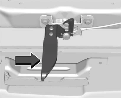 Pull the hood release lever with the i symbol. It is on the lower left side of the instrument panel.
To close the hood:
The Driver Information Center (DIC) will display a message if the hood is not fully closed, and the vehicle is moving. Stop and turn off the vehicle, check the hood for obstructions, and close the hood again.
Check to see if the message still appears on the DIC.
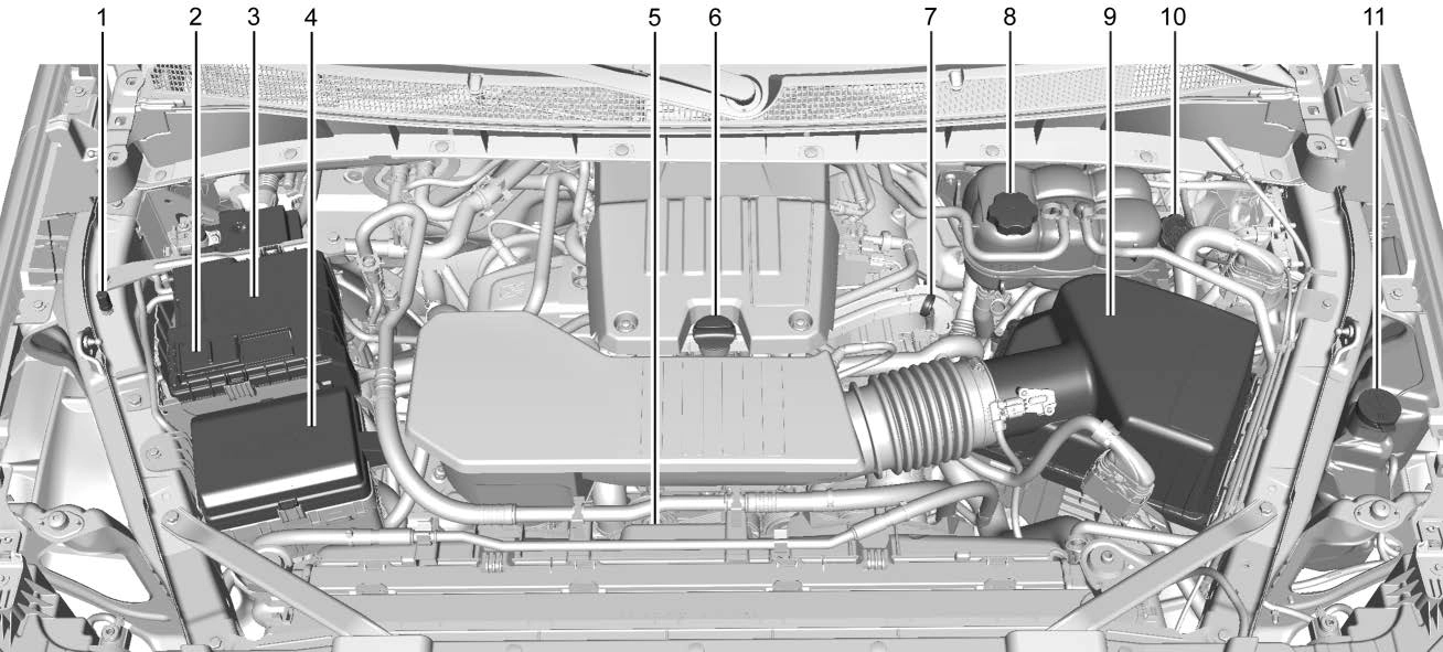
2.7L L4 Engine (L3B)
Jump Starting - North America 0 389.
Cooling System 0 333.
0 341.
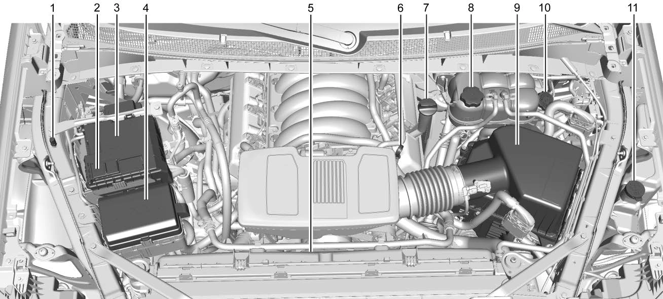
4.3L V6 Engine (LV3)
Jump Starting - North America 0 389.
Cooling System 0 333.
0 341.
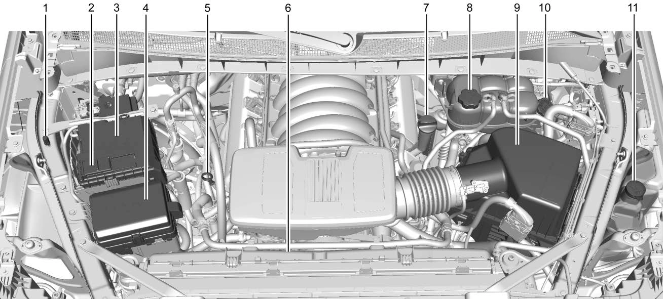
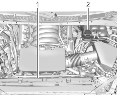
5.3L V8 Engine (L84) Shown, 5.3L V8 Engine (L82) and 6.2L V8 Engine (L87) Similar
Jump Starting - North America 0 389.
Cooling System 0 333.
0 341.
For diesel engine vehicles, see "Engine Oil" in the Duramax diesel supplement.
To ensure proper engine performance and long life, careful attention must be paid to engine oil. Following these simple, but important steps will help protect your investment:
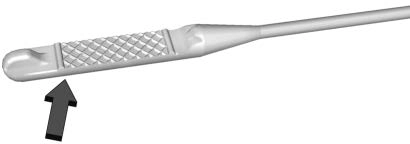
Check the engine oil level regularly, every 650 km (400 mi), especially prior to a long trip. The engine oil dipstick handle is a loop. See Engine Compartment Overview 0 323 for the location.
If a low oil Driver Information Center (DIC) message displays, check the oil level.
Follow these guidelines:

If the oil is below the cross-hatched area at the tip of the dipstick and the engine has been off for at least 15 minutes, add 1 L (1 qt) of the recommended oil and then recheck the level. See "Selecting the Right
Engine Oil" later in this section for an
explanation of what kind of oil to use. For
engine oil crankcase capacity, see Capacities and Specifications 0 421.
See Engine Compartment Overview 0 323 for the location of the engine oil fill cap.
Add enough oil to put the level somewhere in the proper operating range. Push the dipstick all the way back in when through.
Selecting the right engine oil depends on both the proper oil specification and viscosity grade. See Recommended Fluids and Lubricants 0 415.
Specification
Use full synthetic engine oils that meet the dexos1 specification. Engine oils that have been approved by GM as meeting the dexos1 specification are marked with the dexos1 approved logo.
Viscosity Grade
Use SAE 0W-20 viscosity grade engine oil for the 5.3L and 6.2L V8 engines.
Use SAE 5W-30 viscosity grade engine oil for the 2.7L L4, and 4.3L V6 engines. Cold Temperature Operation: In an area of extreme cold, where the temperature falls below −29 °C (−20 °F), use SAE 0W-30 oil. An oil of this viscosity grade will provide easier cold starting for the engine at extremely low temperatures.
When selecting an oil of the appropriate viscosity grade, it is recommended to select an oil of the correct specification. See "Specification" earlier in this section.
Do not add anything to the oil. The recommended oils meeting the dexos1 specification are all that is needed for good performance and engine protection.
Engine oil system flushes are not recommended and could cause engine damage not covered by the vehicle warranty.
Used engine oil contains certain elements that can be unhealthy for your skin and could even cause cancer. Do not let used oil stay on your skin for very long. Clean your skin and nails with soap and water, or a good hand cleaner. Wash or properly dispose of clothing or rags containing used engine oil. See the manufacturer's warnings about the use and disposal of oil products.
Used oil can be a threat to the environment. If you change your own oil, be sure to drain all the oil from the filter before disposal.
Never dispose of oil by putting it in the trash or pouring it on the ground, into sewers, or into streams or bodies of water. Recycle it by taking it to a place that collects used oil.
This vehicle has a computer system that indicates when to change the engine oil and filter. This is based on a combination of factors which include engine revolutions, engine temperature, and miles driven. Based on driving conditions, the mileage at which an oil change is indicated can vary considerably. For the oil life system to work properly, the system must be reset every time the oil is changed.
On some vehicles, when the system has calculated that oil life has been diminished, a CHANGE ENGINE OIL SOON message comes on to indicate that an oil change is necessary. Change the oil as soon as possible within the next 1 000 km (600 mi). It is possible that, if driving under the best conditions, the oil life system might indicate that an oil change is not necessary for up to a year. The engine oil and filter must be changed at least once a year and, at this time, the system must be reset. For vehicles without the CHANGE ENGINE OIL SOON message, an oil change is needed when the REMAINING OIL LIFE percentage is near 0%. Your dealer has trained service people who
will perform this work and reset the system. It is also important to check the oil regularly over the course of an oil drain interval and keep it at the proper level.
If the system is ever reset accidentally, the oil must be changed at 5 000 km (3,000 mi) since the last oil change. Remember to reset the oil life system whenever the oil is changed.
Reset the system whenever the engine oil is changed so that the system can calculate the next engine oil change. Always reset the engine oil life to 100% after every oil change. It will not reset itself. To reset the engine oil life system:
Driver Information Center (DIC) (Midlevel and Uplevel) 0 124.
The oil life system can also be reset as follows:
Driver Information Center (DIC) (Midlevel and Uplevel) 0 124.
If the vehicle has a CHANGE ENGINE OIL SOON message and it comes back on when the vehicle is started and/or the oil
life percentage is near 0%, the engine oil life system has not been reset. Repeat the procedure.
It is usually not necessary to check the transmission fluid level. The only reason for fluid loss is a transmission leak or overheated transmission. This vehicle is not equipped with a transmission fluid level dipstick. There is a special procedure for checking and changing the transmission fluid
in these vehicles. Because this procedure is difficult, this should be done at the dealer. Contact the dealer for additional information or the procedure can be found in the service manual. See Publication Ordering Information 0 432.
Change the fluid and filter at the scheduled maintenance intervals listed in Maintenance Schedule 0 406. Be sure to use the transmission fluid listed in Recommended Fluids and Lubricants 0 415.
If equipped, this feature provides the engine air filter’s remaining life and best timing for a change. The timing to change an engine air filter depends on driving and environmental conditions.
When the Driver Information Center (DIC) displays a message to replace the engine air filter at the next oil change, follow this timing.
When the DIC displays a message to replace the engine air filter soon, replace the engine air filter at the earliest convenience.
The system must be reset after the engine air filter is changed.
If the DIC displays a message to check the engine air filter system, see your dealer.
To reset:
Driver Information Center (DIC) (Midlevel and Uplevel) 0 124.
Select Reset then press the thumbwheel or press the reset stem for several seconds.
The engine air cleaner/filter is on the driver side of the engine compartment. See Engine Compartment Overview 0 323.
If the vehicle is not equipped with the engine air filter life system see Maintenance Schedule 0 406 for intervals on inspecting and replacing the engine air cleaner filter.
Do not start the engine or have the engine running with the engine air cleaner/filter housing open. Before removing the engine air cleaner/filter, make sure that the engine air cleaner/filter housing and nearby components are free of dirt and debris. Do not clean the engine air cleaner/filter or components with water or compressed air.
To inspect or replace the engine air cleaner/ filter:
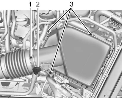
5.3L V8 Engine (L84) Shown, 2.7L L4 Engine (L3B), 4.3L V6 Engine (LV3), 5.3L V8 Engine
(L82), and 6.2L V8 Engine (L87) Similar
0 323.
0 331.
Cooling System
If the vehicle has the Duramax diesel engine, see the Duramax diesel supplement.
The cooling system allows the engine to maintain the correct working temperature.
2.7L L4 Engine (L3B)
4.3L V6 Engine (LV3)
The cooling system in the vehicle is filled with DEX-COOL engine coolant. This coolant is designed to remain in the vehicle for
5 years or 240 000 km (150,000 mi), whichever occurs first.
The following explains the cooling system and how to check and add coolant when it is low. If there is a problem with engine overheating, see Engine Overheating 0 336.
Use a 50/50 mixture of clean, drinkable water and DEX-COOL coolant. This mixture:
Never dispose of engine coolant by putting it in the trash, or by pouring it on the ground, or into sewers, streams, or bodies of water. Have the coolant changed by an authorized service center, familiar with legal requirements regarding used coolant disposal. This will help protect the environment and your health.
The coolant surge tank is in the engine compartment on the driver side of the vehicle. See Engine Compartment Overview 0 323.
The vehicle must be on a level surface when checking the coolant level.
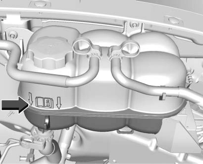
All Engines
Check to see if coolant is visible in the coolant surge tank. If the coolant inside the coolant surge tank is boiling, wait until it cools down. The coolant level should be at or above the indicated mark. If it is not, there may be a leak in the cooling system.
If coolant is visible but the coolant level is not at or above the indicated mark, see the following sections on how to add coolant to the coolant surge tank following.
This feature assists in filling and removing air from the cooling system after service of components or when coolant is added after being too low.
To activate the fill and air removal process:
A hiss means there is still some pressure left.
Ignition Positions (Key Access) 0 228.
If the tank empties, turn the ignition off, allow the Electronic Control Module (ECM) to go to sleep, about two minutes, refill to the indicated mark, and repeat Steps 5–9.
If the vehicle has a diesel engine, see "Cooling System" in the Duramax diesel supplement for the proper coolant fill procedure.
If no coolant is visible in the surge tank, add coolant.
Turn the pressure cap slowly counterclockwise about one full turn. If a hiss is heard, wait for that to stop.
A hiss means there is still some pressure left.
By this time, the coolant level inside the coolant surge tank may be lower. If the level is lower, add more of the proper mixture to the coolant surge tank until the level reaches the indicated mark.
If necessary, repeat coolant fill procedure Steps 1–6.
If the vehicle has the Duramax diesel engine, see the Duramax diesel supplement.
The vehicle has several indicators to warn of engine overheating.
There is a coolant temperature gauge in the vehicle's instrument cluster. See Engine Coolant Temperature Gauge 0 111.
In addition, there are ENGINE OVERHEATED STOP ENGINE, ENGINE OVERHEATED IDLE ENGINE, and ENGINE POWER IS REDUCED
messages in the Driver Information Center (DIC).
If the decision is made not to lift the hood when this warning appears, get service help right away. See Roadside Assistance Program 0 428.
If the decision is made to lift the hood, make sure the vehicle is parked on a level surface.
2.7L L4, 4.3L V6, 5.3L V8, and 6.2L V8 Engines
Check to see if the engine cooling fans are running. If the engine is overheating, the fans should be running. If they are not, do not continue to run the engine and have the vehicle serviced.
If the engine or transmission detects an impending hot fluid condition, then the transmission may force upshifts to limit temperatures. Downshifts may also be prevented in this instance. Normal operation may continue unless the display indicates there is a hot condition and engine should be idled.
If No Steam is Coming from the Engine Compartment
The ENGINE OVERHEATED STOP ENGINE or the ENGINE OVERHEATED IDLE ENGINE
message, along with a low coolant condition, can indicate a serious problem.
The 2.7L L4 engine will shut down automatically if the ENGINE OVERHEATED STOP ENGINE message displays.
If there is an engine overheat warning, but no steam is seen or heard, the problem may not be too serious. Sometimes the engine can get a little too hot when the vehicle:
If the ENGINE OVERHEATED STOP ENGINE or the ENGINE OVERHEATED IDLE ENGINE
message appears with no sign of steam, try this for a minute or so:
If the temperature overheat gauge is no longer in the overheat zone or an overheat warning no longer displays, the vehicle can be driven. Continue to drive the vehicle slowly for about 10 minutes. Keep a safe vehicle distance from the vehicle in front. If the warning does not come back on, continue to drive normally and have the cooling system checked for proper fill and function.
If the warning continues, pull over, stop, and park the vehicle right away.
If there is still no sign of steam and the vehicle is equipped with an engine driven cooling fan, push down the accelerator until the engine speed is about twice as fast as normal idle speed for at least five minutes while the vehicle is parked. If the warning is still there, turn off the engine and get everyone out of the vehicle until it
cools down.
If there is no sign of steam, idle the engine for five minutes while parked. If the warning is still displayed, turn off the engine until it cools down.
If an overheated engine condition exists and the ENGINE POWER IS REDUCED message displays, an overheat protection mode which alternates firing groups of cylinders helps to prevent engine damage. In this mode, a loss in power and engine performance will be noticed. This operating mode allows the vehicle to be driven to a safe place in an emergency. Driving extended distances and/ or towing a trailer in the overheat protection mode should be avoided.
If the engine or transmission detects an impending hot fluid condition, then the transmission may force upshifts to limit temperatures. Downshifts may also be prevented in this instance. Normal operation may continue unless the display indicates there is a hot condition and engine should be idled.
If the vehicle has the Duramax diesel engine, see the Duramax diesel supplement.
The vehicle has electric cooling fan(s). The fans may be heard spinning at low speed during most everyday driving. The fans may turn off if no cooling is required. Under heavy vehicle loading, trailer towing, high
outside temperatures, or operation of the air conditioning system, the fans may change to high speed and an increase in fan noise may be heard. This is normal and indicates that the cooling system is functioning properly. The fans will change to low speed when additional cooling is no longer required.
The electric engine cooling fans may run after the engine has been turned off. This is normal and no service is required.
When windshield washer fluid needs to be added, be sure to read the manufacturer's instructions before use. Use a fluid that has sufficient protection against freezing in an area where the temperature may fall below freezing.
The vehicle has a low washer fluid message on the DIC that comes on when the washer fluid is low. The message is displayed for 15 seconds at the start of each ignition cycle. When the WASHER FLUID LOW ADD FLUID
 message displays, washer fluid will need to be added to the windshield washer fluid reservoir.
Open the cap with the washer symbol on it. Add washer fluid until the tank is full. See Engine Compartment Overview 0 323 for reservoir location.
Disc brake linings have built-in wear indicators that make a high-pitched warning sound when the brake linings are worn and new linings are needed. The sound can come and go or can be heard all the time when the vehicle is moving, except when applying the brake pedal firmly.
Some driving conditions or climates can cause a brake squeal when the brakes are first applied, clearing up following several applies. This does not mean something is wrong with the brakes.
Properly torqued wheel nuts are necessary to help prevent brake pulsation. When tires are rotated, inspect brake linings for wear and evenly tighten wheel nuts in the proper sequence to torque specifications. See Capacities and Specifications 0 421.
Brake pads should be replaced as complete axle sets.
See your dealer if the brake pedal does not return to normal height, or if there is a rapid increase in pedal travel. This could be a sign that brake service may be required.
Always replace brake system parts with new, approved replacement parts. If this is not done, the brakes may not work properly. The braking performance can change in many ways if the wrong brake parts are installed or if parts are improperly installed.
This vehicle has a system that estimates the remaining life of the front and rear brake pads. Brake pad life is displayed in the Driver Information Center (DIC), along with
a percentage for each axle. The system must be reset every time the brake pads are changed.
When the system has determined that the brake pads need to be replaced, a message will display, which may include mileage remaining.
Brake pads should always be replaced as complete axle sets.
The system will automatically detect when significantly worn brake pads are replaced. When the ignition is turned on after new pads and wear sensors are installed, a message will display. Follow the prompts to reset the system.
The brake pad life system can also be manually reset:
Driver Information Center (DIC) (Midlevel and Uplevel) 0 124.
The brake pad life system can be turned off. This may be necessary if aftermarket brake pads without wear sensors are installed.
When the system is turned off, the front and rear brake pad life percentages will not display. However, the built-in wear indicators that make a high-pitched warning sound when the brake pads are worn can still determine when the pads should be replaced. See Brakes 0 339.
To turn off the brake pad life system:
Driver Information Center (DIC) (Midlevel and Uplevel) 0 124.
To turn the brake pad life system back on, follow the above steps but select ENABLE in Step 2.
The brake master cylinder reservoir is filled with GM approved DOT 4 brake fluid as indicated on the reservoir cap. See Engine Compartment Overview 0 323 for the location of the reservoir.
Checking Brake Fluid
With the vehicle in P (Park) on a level surface, the brake fluid level should be between the minimum and maximum marks on the brake fluid reservoir.
There are only two reasons why the brake fluid level in the reservoir may go down:
With a leak, the brakes will not work well.
Always clean the brake fluid reservoir cap and the area around the cap before removing it.
Do not top off the brake fluid. Adding fluid does not correct a leak. If fluid is added when the linings are worn, there will be too much fluid when new brake linings are installed. Add or remove fluid, as necessary, only when work is done on the brake hydraulic system.
When the brake fluid falls to a low level, the brake warning light comes on. See Brake System Warning Light 0 116.
Brake fluid absorbs water over time which degrades the effectiveness of the brake fluid. Replace brake fluid at the specified intervals to prevent increased stopping distance. See Maintenance Schedule 0 406.
What to Add
Use only GM approved DOT 4 brake fluid from a clean, sealed container. See Recommended Fluids and Lubricants 0 415.
The original equipment battery is maintenance free. Do not remove the cap and do not add fluid.
Refer to the replacement number shown on the original battery label when a new battery is needed. See Engine Compartment Overview 0 323 for battery location.
Stop/Start System
Vehicles equipped with a 2.7L L3B, 3.0L LM2, 5.3L L84 or 6.2L L87 are equipped with a Stop/Start system to shut off the engine to help conserve fuel. See Stop/Start System
0 232.
Vehicles with the Stop/Start system have an Absorbed Glass Mat (AGM) 12-volt battery. Installation of a standard 12-volt battery will result in reduced 12-volt battery life. When using a 12-volt battery charger on the 12-volt AGM battery, some chargers have an AGM battery setting on the charger. If available, use the AGM setting on the charger to limit charge voltage to 14.8 volts. Follow the charger manufacturer’s instructions.
See California Proposition 65 Warning 0 320
and the back cover.
Negative Battery Cable Disconnection
Infrequent Usage: Remove the black, negative (−) cable from the battery to keep the battery from running down.
Extended Storage: Remove the black, negative (−) cable from the battery or use a battery trickle charger.
For vehicles equipped with the Stop/Start system:
non-conductive material to prevent any contact with the negative battery cable.
For vehicles not equipped with the Stop/ Start system:
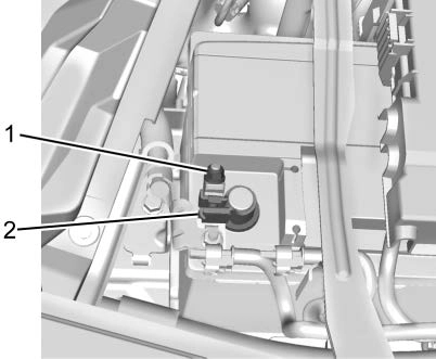
clamp (2) from the negative battery post.
non-conductive material to prevent any contact with the negative battery cable.
For vehicles equipped with the Stop/Start system:
For vehicles not equipped with the Stop/ Start system:
When to Check Lubricant
Refer to Maintenance Schedule 0 406 to determine when to check the lubricant.
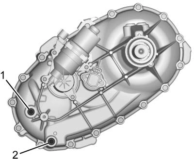
To get an accurate reading, the vehicle should be on a level surface.
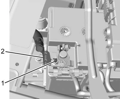
If the level is below the bottom of the fill plug (1) hole, located on the transfer case, some lubricant will need to be added. Add enough lubricant to raise the level to the bottom of the fill plug (1) hole. Use care not to overtighten the plug.
When to Change Lubricant
Refer to Maintenance Schedule 0 406 to determine how often to change the lubricant.
What to Use
Refer to Recommended Fluids and Lubricants 0 415 to determine what kind of lubricant to use.
When to Check Lubricant
It is not necessary to regularly check the front axle fluid unless a leak is suspected or an unusual noise is heard. A fluid loss could indicate a problem. Have it inspected and repaired. This service can be complex. See your dealer.
Do not directly power wash the transfer case and/or front/rear axle output seals. High pressure water can overcome the seals and contaminate the fluid. Contaminated fluid will decrease the life of the transfer case and/or drive axles and should be replaced.
When to Check Lubricant
It is not necessary to regularly check the rear axle fluid unless a leak is suspected or an unusual noise is heard. A fluid loss could indicate a problem. Have it inspected and repaired. This service can be complex. See your dealer.
Do not directly power wash the transfer case and/or front/rear axle output seals. High pressure water can overcome the seals and contaminate the fluid. Contaminated fluid will decrease the life of the transfer case and/or drive axles and should be replaced.
Do not use the accelerator pedal, and be ready to turn off the engine immediately if it starts.
It should be parked on a level surface.
If equipped with Key Access ignition, while parked, and with the parking brake set, try to turn the ignition off in each shift lever position. The ignition should turn to off only when the shift lever is in P (Park).
The ignition key should come out only when the ignition is off. Contact your dealer if service is required.
Park on a fairly steep hill, with the vehicle facing downhill. Keeping your foot on the regular brake, set the parking brake.
Contact your dealer if service is required.
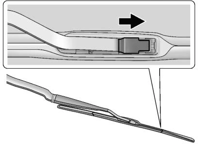
Windshield wiper blades should be replaced periodically. See Maintenance Schedule
0 406.
Replacement blades come in different types and are removed in different ways. For proper type and length, see Maintenance Replacement Parts 0 416.
To replace the wiper blade:
If the windshield or front side glass must be replaced, see your dealer to determine the correct replacement glass.
The windshield is part of the HUD system. If the windshield must be replaced, get one that is designed for HUD or the HUD image may look out of focus.
If the windshield needs to be replaced and the vehicle is equipped with a front camera sensor for the Driver Assistance Systems, a GM replacement windshield is recommended. The replacement windshield must be installed according to GM specifications for proper alignment. If it is
not, these systems may not work properly, they may display messages, or they may not work at all. See your dealer for proper windshield replacement.
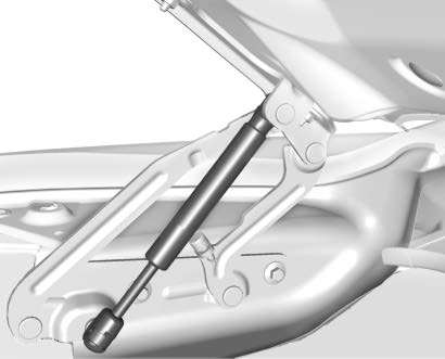
This vehicle is equipped with gas strut(s) to provide assistance in lifting and holding open the hood/trunk/liftgate system in full open position.
See Maintenance Schedule 0 406.
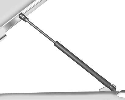
Hood
Trunk
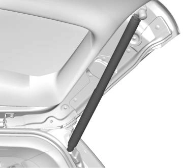
Liftgate
Download Manual