Other interior features
position, flip it down.
To set the visor in the side posi- tion, flip down, unhook, and swing it to the side.
To use the side extender, place the visor in the side position, then slide it backward.
Slide the cover to open.
Vehicles with vanity lights: The light turns on when the cover is opened.
Vehicles with vanity lights: If the vanity lights remain on for 20 minutes while
the engine is off, the lights will turn off automatically.
5-4. Other interior features
381
Open the lid.
Vehicles without a smart key system:
The power outlet can be used when the engine switch is in the “ACC” or “ON” position.
Vehicles with a smart key system:
The power outlet can be used when the engine switch is in ACCESSORY or IGNITION ON mode.
382 5-4. Other interior features
The USB charging ports are for charging only. They are not designed for data transfer or other purposes.
Depending on the external device, it may not charge properly. Refer to the manual included with the device before using a USB charging port.
Open the console box lid and open the lid.
The engine switch is in ACCESSORY or IGNITION ON mode.
Depending on the connected external device, charging may occasionally be suspended and then start again. This is not a malfunction.
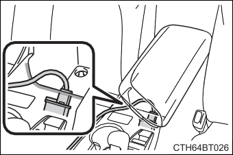 The shape of the console box rim allows power cables to be passed through when the console box lid is closed.
5-4. Other interior features
383
384 5-4. Other interior features
The wireless charger cannot be used with a portable device that is larger than the charging area. Additionally, depending on the portable device, the wireless charger may not operate properly. Refer to the operation manual of the portable device.
The “Qi” symbol is a trademark of the Wireless Power Consortium.
Power supply switch Operation indicator light Charge area
Press the power supply switch of the wireless char- ger.
Pressing the switch again turns the wireless charger off.
When turned on, the operation indicator light (green) comes on.
When the engine switch is turned off, the on/off state of the wireless charger will be memo- rized.
While charging, the operation indicator light (orange) will be illuminated.
If charging does not begin, move the portable device as close to the center of the charging area as possible.
5-4. Other interior features
385
When charging is complete, the operation indicator light (green) will illu- minate.
386 5-4. Other interior features
|
Operation indicator light |
State |
|
Off |
The Wireless charger is off |
|
Green (illuminated) |
Standby (charging is possible) |
|
Charging is complete* |
|
|
Orange (illuminated) |
A portable device has been placed on the charging area (identifying the portable device) |
|
Charging in progress |
*: Depending on the portable device, the operation indicator light may stay illuminated (orange) after charging has completed.
If an error is detected, the operation indicator light will blink (orange). Take the appropriate measures according to the table below.
|
Operation indicator light |
Suspected causes |
Measure |
||
|
Blinks (orange) at a one second interval continuously |
Vehicle to charger com- munication failure. |
Contact dealer. |
your |
Toyota |
|
Blinks (orange) 3 times repeatedly |
A foreign object exists between the portable device and charging area. |
Remove object. |
the |
foreign |
|
Portable device is not positioned properly on the charging area. |
Move the portable device toward the cen- ter of the charging area. |
|||
|
Blinks (orange) 4 times repeatedly |
The temperature of the wireless charger is excessively high. |
Stop charging immedi- ately and continue charging after a while. |
5-4. Other interior features
387
The engine switch is in ACCESSORY or IGNITION ON mode.
Do not charge a portable device if a cover or accessory which is not Qi com- patible is attached. Depending on the type of cover and/or accessory attached, it may not be possible to charge the portable device. If the portable device is placed on the charging area and does not charge, remove the cover and/or accessories.
Turn off the wireless charger and check if the noise is reduced. If noise is reduced, press and hold the power supply switch of the wireless charger for 2 seconds. The frequency of the wireless charger is changed and noise may be reduced. When the frequency is changed, the operation indicator light will blink (orange) 2 times.
If a portable device becomes warm while charging and charging stops due to the protection function of the portable device, wait until the portable device cools down and charge it again.
When the power supply switch is turned on or while a portable device is being identified, operation sounds may be heard. This is not a malfunction.
P. 418
388 5-4. Other interior features
 5-4. Other interior features
389
 390 5-4. Other interior features
5-4. Other interior features
391
392 5-4. Other interior features
NOTICE
In the following situations, the wireless charger may not operate correctly:
If in situations other than above the wireless charger does not operate prop- erly or the operation indicator light is blinking, the wireless charger may be malfunctioning. Contact your Toyota dealer.
Additionally, do not bring precision instruments such as wrist watches, close to the wireless charger, as such objects may malfunction.
Do not use the wireless charger for a long period of time with the engine stopped.
5-4. Other interior features
393
An assist grip installed on the ceil- ing can be used to support your body while sitting on the seat.
394 5-4. Other interior features
rear assist grips.
5-4. Other interior features
395
which can be programmed to operate 3 different devices. Refer to the programming methods on the following pages to determine the method which is appropriate for the device.
HomeLink® indicator light
Garage door operation indica- tors
Buttons
*: If equipped
396 5-4. Other interior features
Press and release the HomeLink® button you want to program and check that the HomeLink® indicator light flashes orange.
Point the remote control transmitter for the device at the rear view mirror, 1 to 3 in. (25 to 75 mm) from the HomeLink® buttons.
Keep the HomeLink® indicator light in view while programming.
Programming a device other than an entry gate (for U.S.A. owners)
Press and hold the remote control transmitter button until the HomeLink® indicator light changes from slowly flashing orange to rapidly flashing green (rolling code) or continuously lit green (fixed code), then release the button.
Programming an entry gate (for U.S.A. owners)/Programming a device in the Canadian market
Press and release the remote control transmitter button at 2 sec- ond intervals, repeatedly, until the HomeLink® indicator light changes from slowly flashing orange to rapidly flashing green (rolling code) or continuously lit green (fixed code).
5-4. Other interior features
397
Repeat the steps above to program another device for any of the remaining HomeLink® buttons.
2 or more people may be necessary to complete rolling code pro- gramming.
Locate the “Learn” or “Smart” button on the garage door opener motor in the garage.
This button can usually be found where the hanging antenna wire is attached to the unit. The name and color of the button may vary by manufacturer. Refer to the Owner’s manual supplied with the garage door opener motor for details.
Perform within 30 sec- onds after performing .
398 5-4. Other interior features
If the garage door opener motor operates when the HomeLink® button is
pressed, the garage door opener motor recognizes the HomeLink® signal.
When enabled, 2-way communication allows you to check the sta- tus of the opening and closing of a garage door through indicators in your vehicle.
2-way communication is only available if the garage door opener motor used is a compatible device. (To check device compatibility, refer to www.HomeLink.com.)
Within 5 seconds after programming the garage door opener has been completed, if the garage door opener motor is trained to HomeLink®, both garage door operation indicators will flash rap- idly green and the light on the garage door opener motor will blink twice, indicating that 2-way communication is enabled.
If the indicators do not flash, perform and within the first 10 presses of the HomeLink® button after programming has been completed.
Press a programmed HomeLink® button to operate a garage door.
Within 1 minute of pressing the HomeLink® button, after the garage door operation has stopped, press the “Learn” or “Smart” button on the garage door opener motor. Within 5 seconds of the establishment of 2-way communication with the garage door opener, both garage door operation indicators in the vehicle will flash rapidly green and the light on the garage door opener motor will blink twice, indicating that 2-way communication is enabled.
5-4. Other interior features
399
With one hand, press and hold the desired HomeLink® button.
When the HomeLink® indicator starts flashing orange, continue to hold the HomeLink® button and perform “Programming the HomeLink®” (it takes 20 seconds for the HomeLink® indicator
to start flashing).
Press the appropriate HomeLink® button. The HomeLink® indicator light should turn on.
The status of the opening and closing of a garage door is shown by the indicators.
Opening Closing
This function is only available if the garage door opener motor used is a compatible device. (To check device compatibility, refer to www.HomeLink.com.)
|
Color |
Status |
|
Orange (flashing) |
Currently opening/closing |
|
Green |
Opening/closing has completed |
|
Red (flashing) |
Feedback signals cannot be received |
buttons and or and simultane- ously. The last recorded status will be displayed for 3 seconds.
400 5-4. Other interior features
tons for 10 seconds until the HomeLink® indicator light changes from continuously lit orange to rapidly flashing green.
If you sell your vehicle, be sure to erase the programs stored in the HomeLink® memory.
For vehicles sold in the U.S.A.
For vehicles sold in Canada
5-4. Other interior features
401
Visit on the web at www.homelink.com/toyota or call 1-800-355-3515.
402 5-4. Other interior features
LED light indicators “SOS” button
*: If equipped
5-4. Other interior features
403
Helps drivers receive necessary response from emergency ser- vice providers. (P. 404)
*: U.S. Patent No. 7,508,298 B2
Helps drivers in the event of vehicle theft. (P. 405)
Connects drivers to response-center support. (P. 405)
Provides drivers various on-road assistance. (P. 405)
After you have signed the Telematics Subscription Service Agree- ment and are enrolled, you can begin receiving services.
A variety of subscription terms are available for purchase. Contact your Toyota dealer, call the Safety Connect response center at 1- 855-405-6500, or push the “SOS” button in your vehicle for further subscription details.
404 5-4. Other interior features
The Safety Connect response center will offer support in multiple languages. The Safety Connect system will offer voice prompts in English and Spanish. Please indicate your language of choice when enrolling.
You may be unable to contact the response center if the network is busy.
The following indicator light patterns indicate specific system usage conditions:
In case of either airbag deployment or severe rear-end collision, the system is designed to automatically call the response center. The responding agent receives the vehicle’s location and attempts to speak with the vehicle occupants to assess the level of emergency. If the occupants are unable to communicate, the agent automati- cally treats the call as an emergency, contacts the nearest emer- gency services provider to describe the situation, and requests that assistance be sent to the location.
5-4. Other interior features
405
In addition to assisting law enforcement with recovery of a stolen vehicle, Safety-Connect-equipped vehicle location data may, under certain circumstances, be shared with third parties to locate your vehicle. Further information is available at Toyota.com.
In the event of an emergency on the road, push the “SOS” button to reach the Safety Connect response center. The answering agent will determine your vehicle’s location, assess the emergency, and dispatch the necessary assistance required.
If you accidentally press the “SOS” button, tell the response-center agent that you are not experiencing an emergency.
Subscribers can press the “SOS” button to reach a Safety Connect response-center agent, who can help with a wide range of needs, such as: towing, flat tire, fuel delivery, etc. For a description of the Enhanced Roadside Assistance services and their limitations, please see the Safety Connect Terms and Conditions, which are available at Toyota.com.
406 5-4. Other interior features
The Safety Connect system installed in your vehicle is a low-power radio transmitter and receiver. It receives and also sends out radio frequency (RF) signals.
In August 1996, the Federal Communications Commission (FCC) adopted RF exposure guidelines with safety levels for mobile wire- less phones. Those guidelines are consistent with the safety stan- dards previously set by the following U.S. and international standards bodies.
Those standards were based on comprehensive and periodic eval- uations of the relevant scientific literature. Over 120 scientists, engi- neers, and physicians from universities, and government health agencies and industries reviewed the available body of research to develop the ANSI Standard (C95.1).
The design of Safety Connect complies with the FCC guidelines in addition to those standards.
5-4. Other interior features
407
408 5-4. Other interior features
press and hold the button for 3 seconds.
|
Display |
Direction |
|
N |
North |
|
NE |
Northeast |
|
E |
East |
|
SE |
Southeast |
|
S |
South |
|
SW |
Southwest |
|
W |
West |
|
NW |
Northwest |
*: If equipped
5-4. Other interior features
409
If you cross over a map boundary shown in illustration, the compass will deviate.
To obtain higher precision or perfect calibration, refer to the following.
Press and hold the button for 6 seconds.
A number (1 to 15) appears on the compass display.
If the direction is displayed several seconds after adjustment, the cali- bration is complete.
410 5-4. Other interior features
Press and hold the button for 9 seconds.
“C” appears on the compass display.
If there is not enough space to drive in a circle, drive around the block until the direction is dis- played.
The compass may not show the correct direction in the following conditions:
(There is a magnet or metal object near the inside rear view mirror.)
5-4. Other interior features
411
412 5-4. Other interior features
Download Manual