Tire information
& Tire labeling
Many markings (e.g. Tire size, Tire Identification Number or TIN) are placed on the sidewall of a tire by tire manufacturers. These markings can provide you with useful infor- mation on the tire.
! Tire size
Your vehicle comes equipped with P-Metric tire size. It is important to understand the sizing system in selecting the proper tire for your vehicles. Here is a brief review of the tire sizing system with a break- down of its individual elements.
! P Metric
With the P-Metric system, Section Width is measured in millimeters. To convert millimeters into inches, divide by 25.4. The Aspect Ratio (Section Height divided by Section Width) helps provide more dimen- sional information about the tire size.
Example:
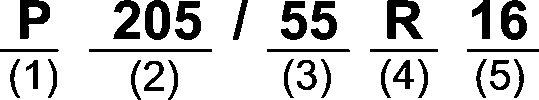
7 section width).
! Load and Speed Rating Descriptions
The load and speed rating descrip- tions will appear following the size designation.
They provide two important facts about the tire. First, the number designation is its load index. Sec- ond, the letter designation indicates the tire’s speed rating.
Example: individual elements.


For example, “90” means 1,323 lbs
(600 kg), “89” means 1,278 lbs (580 kg).
For example, “V” means 149 mph (240 km/h)
! Tire Identification Number (TIN)
Tire Identification Number (TIN) is marked on the intended outboard sidewall. The TIN is composed of four groups. Here is a brief review of the TIN with a breakdown of its
The first two figures identify the week, starting with “01” to represent the first full week of the calendar year; the second two figures repre- sent the year. For example, 0101 means the 1st week of 2001.
! Other markings
The following makings are also placed on the sidewall.
! Maximum permissible infla- tion pressure
The maximum cold inflation pres- sure to which this tire may be inflated. For example, “300 kPa (44 PSI) MAX. PRESS”
! Maximum load rating
The load rating at the maximum permissible weight load for this tire. For example, “MAX. LOAD 580 kg (1279 LBS) @ 300 kPa (44 PSI) MAX. PRESS.”
! Construction type Applicable construction of this tire. For example, “TUBELESS STEEL
! Construction
The generic name of each cord material used in the plies (both sidewall and tread area) of this tire. For example, “PLIES: TREAD 2
STEEL + 2 POLYESTER SIDE- WALL 2 POLYESTER”
! Uniform Tire Quality Grad- ing (UTQG)
For details, refer to “Uniform tire quality grading standards” P526.
& Recommended tire inflation pressure
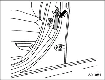 ! Vehicle placard
The vehicle placard is attached to the driver’s side door pillar.
Example:
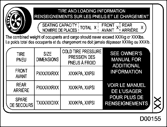
The vehicle placard shows original tire size, recommended cold tire inflation pressure on each tire at maximum loaded vehicle weight, seating capacity and loading infor- mation.
! Adverse safety conse- quences of under-inflation
Driving at high speeds with exces- sively low tire pressures can cause the tires to flex severely and to rapidly become hot. A sharp in-
crease in temperature could cause tread separation, and failure of the tire(s). Possible resulting loss of vehicle control could lead to an accident.
! Measuring and adjusting air pressure to achieve proper inflation
Check and, if necessary, adjust the pressure of each tire (including the spare) at least once a month and before any long journey. Check the tire pressures when the tires are cold. Use a pressure gauge to adjust the tire pressures to the specific values. Driving even a short distance warms up the tires and increases the tire pressures. Also, the tire pressures are affected by the outside temperature. It is best to check tire pressure outdoors before driving the vehicle. When a tire becomes warm, the air inside it expands, causing the tire pressure to increase. Be careful not to mis- takenly release air from a warm tire to reduce its pressure.
& Glossary of tire terminology
The combined weight (in excess of those standard items which may be replaced) of automatic transmis- sion, power steering, power brakes, power windows, power seats, radio, and heater, to the extent that these items are available as factory-in- stalled equipment (whether in- stalled or not).
The part of the tire that is made of steel wires, wrapped or reinforced by ply cords and that is shaped to fit the rim.
A breakdown of the bond between components in the bead.
A pneumatic tire in which the ply cords that extend to the beads are laid at alternate angles substantially less than 90 degrees to the center- line of the tread.
The tire structure, except tread and
sidewall rubber which, when in- flated, bears the load.
The breaking away of pieces of the tread or sidewall.
The pressure in a tire that has been driven less than 1 mile or has been standing for three hours or more.
The strands forming the plies in the tire.
The parting of cords from adjacent rubber compounds.
Any parting within the tread, side- wall, or inner liner of the tire extending to cord material.
The weight of a motor vehicle with standard equipment including the maximum capacity of fuel, oil and coolant, and if so equipped, air conditioning and additional weight optional engine.
A tire designed to operate at higher loads and higher inflation pressure than the corresponding standard tire.
The space between two adjacent tread ribs.
The layer(s) forming the inside sur- face of a tubeless tire that contains the inflating medium within the tire.
The parting of the innerliner from cord material in the carcass.
a vehicle.
A tire designated by its manufac- turer as primarily intended for use on lightweight trucks or multipur- pose passenger vehicles.
The maximum load that a tire is rated to carry for a given inflation pressure.
The load rating for a tire at the maximum permissible inflation pressure for that tire.
The sum of:
The maximum cold inflation pres- sure to which a tire may be inflated.
The rim on which a tire is fitted for physical dimension requirements.
150 lbs (68 kg) times the number of occupants specified in the second column of Table 1 that is appended to the end of this section.
Any parting at any junction of tread, sidewall, or innerliner that extends to cord material.
The overall diameter of an inflated new tire.
The linear distance between the exteriors of the sidewalls of an inflated tire, including elevations due to labeling, decorations, or protective bands or ribs.
A tire intended for use on passen- ger cars, multipurpose passenger vehicles, and trucks, that have a gross vehicle weight rating (GVWR) of 10,000 lbs (4,535 kg) or less.
A layer of rubber-coated parallel cords.
A parting of rubber compound between adjacent plies.
A mechanical device made of rub- ber, chemicals, fabric and steel or other materials, that, when mounted on an automotive wheel, provides the traction and contains the gas or fluid that sustains the load.
The combined weight of those installed regular production options weighing over 5.1 lbs (2.3 kg) in excess of those standard items which they replace, not previously considered in curb weight or acces-
sory weight, including heavy duty brakes, ride levelers, roof rack, heavy duty battery, and special trim.
A pneumatic tire in which the ply cords that extend to the beads are laid at substantially 90 degrees to the centerline of the tread.
The cold inflation pressure recom- mended by a vehicle manufacturer.
A tire designed to operate at higher loads and at higher inflation pres- sures than the corresponding stan- dard tire.
A metal support for a tire or a tire and tube assembly upon which the tire beads are seated.
Nominal diameter of the bead seat.
Rim diameter and width.
The industry of manufacturer’s des- ignation for a rim by style or code.
Nominal distance between rim flanges.
The linear distance between the exteriors of the sidewalls of an inflated tire, excluding elevations due to labeling, decoration, or pro- tective bands.
That portion of a tire between the tread and bead.
The parting of the rubber compound from the cord material in the side- wall.
A tire that attains a traction index equal to or greater than 110, com- pared to the ASTM E-1136 Stan- dard Reference Test Tire, when using the snow traction test as described in ASTM F-1805-00, Standard Test Method for Single
 Wheel Driving Traction in a Straight Line on Snow-and Ice-Covered Surfaces, and which is marked with an Alpine Symbol “ ” on at least one sidewall.
The rim on which a tire is fitted for testing, and it may be any rim listed as appropriate for use with that tire.
That portion of a tire that comes into contact with the road.
A tread section running circumfer- entially around a tire.
Pulling away of the tread from the tire carcass.
The projections within the principal grooves designed to give a visual indication of the degrees of wear of the tread.
The rated cargo and luggage load plus 150 lbs (68 kg) times the vehicle’s designated seating capa-
city.
The fixture used to hold the wheel and tire assembly securely during testing.
Table 1 — Occupant loading and distribution for vehicle normal load for various designated seating capacities
|
Designated seating capacity, number of occupants |
Vehicle normal load, number of occupants |
Occupant distribution in a normally loaded vehicle |
|
2 through 4 |
2 |
2 in front. |
|
5 through 10 |
3 |
2 in front, 1 in second seat. |
|
11 through 15 |
5 |
2 in front, 1 in second seat, 1 in third seat, 1 in fourth seat. |
|
16 through 22 |
7 |
2 in front, 2 in second seat, 2 in third seat, 1 in fourth seat. |
& Tire care – maintenance and safety practices
P473. Replace any damaged or
rotation. After tire rotation, adjust the tire pressures and make sure the wheel nuts are correctly tigh- tened. For information about the tightening torque and tightening sequence for the wheel nuts, refer to “Flat tires” P423.
& Determining compatibility of tire and vehicle load capaci- ties
The sum of four tires’ maximum load ratings must exceed the max- imum loaded vehicle weight (“GVWR”). In addition, sum of the maximum load ratings of two front tires and of two rear tires must exceed each axle’s maximum loaded capacity (“GAWR”). Original equipment tires are designed to fulfill those conditions.
The maximum loaded vehicle weight is referred to Gross Vehicle Weight Rating (GVWR). And each axle’s maximum loaded capacity is referred to Gross Axle Weight Rat- ing (GAWR). The GVWR and each
axle’s GAWR are shown on the vehicle certification label located at the bottom of driver’s side door pillar.
The GVWR and front and rear GAWRs are determined by not only the maximum load rating of tires but also loaded capacities of the vehi- cle’s suspension, axles and other parts of the body.
Therefore, this means that the vehicle cannot necessarily be loaded up to the tire’s maximum load rating on the tire sidewall.
Overloading could affect vehicle handling, stopping distance, and vehicle and tire performance in the following ways. This could lead to an accident and possibly result in severe personal injury.
loads could increase the risk of rollover.
& Steps for Determining Cor- rect Load Limit
luggage load capacity. For exam- ple, if the “XXX” amount equals 1400 lbs. and there will be five 150 lb passengers in your vehicle, the amount of available cargo and luggage load capacity is 650 lbs. (1400− 750 (5 6 150) = 650 lbs.)
Download Manual