Remote engine start system (dealer option)
The remote engine start system allows you to start the engine from outside the vehicle. In addition, the remote engine start system can activate the heater or air conditioner, providing you with a comfortable cabin upon entry. For more details, refer to the Owner’s Manual supplement for the re-
mote engine start system.
NOTE
All vehicle doors (including rear gate) and the engine hood must be closed prior to activating the remote engine start system. Any open entry point will prevent starting or cause the engine to stop.
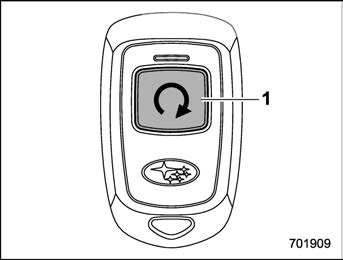
The remote engine start system is acti- vated by pressing the fob button on your remote engine starter transceiver (fob) twice within 3 seconds. If the fob is within operating range of the system and the start request is received, the following will occur.
If the fob is not within range (the user is too far away from the vehicle), the fob will indicate two long flashes without beeping.
The system will check certain safety preconditions before starting, and if all conditions are met, the engine will start within 5 seconds. After the engine starts, the following will occur.
While the engine is idling via the remote engine start system, the following will occur.
If the engine turns over but does not start (or starts and stalls) the remote engine start system will power off and then attempt to start the engine 3 additional times. The system will not attempt to restart the engine if it determines a vehicle malfunction is preventing starting. If the engine does not start after 3 additional attempts, the remote engine start request will be aborted.
Press and hold the fob button for at least 2 seconds to stop the engine. The fob will flash and beep three times, indicating the engine has stopped. If the stop request is not received (for example, if the user is too far away from the vehicle), the fob will continue to flash once every 3 seconds. The system will automatically stop the engine after 15 minutes.
For safety and security reasons, the remote engine start system will prevent starting (or stop the engine if running) and sound the horn twice if any of the following conditions is detected. In addition, the fob will flash and beep 3 times.
If the system detects any door (including the rear gate) open during operation, it will prevent starting or stop the engine, and sound the horn and flash side marker lights, tail lights, and parking lights 6 times.
In addition to the items above, if the vehicle’s engine management system determines there is a safety risk due to a vehicle-related problem, the vehicle will power down and the horn will sound 3 times.
! Remote start operation - fob con- firmation
Your remote engine starter fob is a bidirectional transceiver that can confirm system operation with several different visual and audible indications. The fob’s LED-backlit button and internal piezo buzzer will indicate status of the system using the following flash and beep se- quences, provided the fob is within opera- tional range of the system.
|
Precondition |
Fob Indication |
Meaning |
|
|
Flash |
Beep |
||
|
Fob start button is being pressed |
Continuous while button is held down |
— |
The fob is transmitting an RF signal |
|
User attempts to start engine by pressing fob button twice within 3 sec |
1 flash |
1 beep |
Engine start request received |
|
2 flashes |
2 beeps |
Engine started successfully |
|
|
1 flash every 3 sec |
— |
Engine idling |
|
|
3 flashes |
3 beeps |
Vehicle is in range but engine not started |
|
|
2 long flashes |
— |
Vehicle not in range (engine not started) |
|
|
Engine idling by remote engine start operation |
1 flash every 3 sec |
— |
Engine idling |
|
3 flashes |
3 beeps |
Engine stopped by system timeout or for safety reasons (see sections above) |
|
|
User attempts to stop engine by pressing and holding fob button for at least 2 sec |
3 flashes |
3 beeps |
Engine stopped by user request |
|
1 flash every 3 sec |
— |
Stop request not received. Engine still idling. |
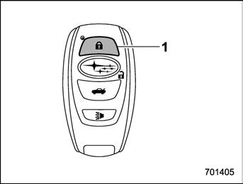
Access key fob
An access key fob can be used as the remote engine start transmitter. Operate the lock button to start or stop the engine as follows.
Before using the remote engine start system to start the engine, confirm the following conditions.
To start the engine with remote engine start system, briefly press the lock button twice within 2 seconds, then press and hold the lock button for 3 seconds.
Press and hold the lock button to stop the engine with remote engine start system.
For detailed information, refer to “Remote start safety features” P310.
P136.
P136.
and beep 3 times to indicate that the remote start system has been shut down.
An alarm trigger may occur if the vehicle is opened by the remote keyless entry transmitter within a few seconds immedi- ately following remote engine start shut- down.
Before exiting the vehicle, set the tem- perature controls to the desired setting and operation. After the system starts the engine, the heater or air conditioning will activate and heat or cool the interior to your setting.
New transmitters can be programmed to the remote engine start system in the event that a transmitter is lost, stolen, damaged or additional transmitters are desired (the system will accept up to eight transmitters). New remote engine start transmitters can be programmed accord-
ing to the following procedure.
 ” button on the transmitter that you want to program.
or after 2 minutes.
In the event that the vehicle’s battery is replaced, discharged or disconnected, it will be necessary to start the vehicle a minimum of one time using the key prior to activating the remote engine start system. This is required to allow the vehicle electronic systems to re- synchronize.
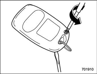
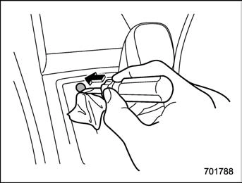
! Changing the battery
For models with “keyless access with push-button start system”:
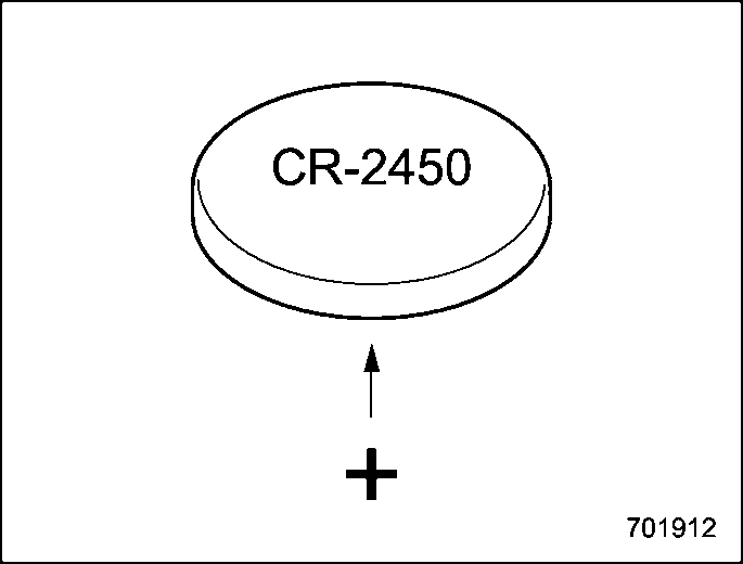
Perform the procedure described in “Re- placing battery of access key fob” P492. For remote engine starter transceiver: The 3-volt lithium battery (model CR-2450) supplied in your remote engine start transmitter should last approximately one year, depending on usage. When the battery begin to weaken, you will notice a
decrease in range (distance from the vehicle that your remote control operates). Follow the instructions below to change the remote engine start transmitter battery.
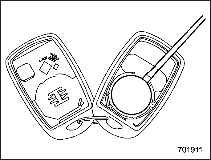
should be pointed away from the transmit- ter circuit board on battery).
NOTE
This device complies with part 15 of the FCC Rules. Operation is subject to the following two conditions: (1) This de- vice may not cause harmful interfer- ence, and (2) this device must accept any interference received, including interference that may cause undesired operation.
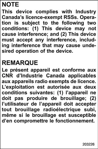
! Canada-spec. models
7-7. Continuously variable transmission
& Continuously variable trans- mission features
The continuously variable transmission is electronically controlled and provides an infinite number of forward speeds and 1 reverse speed. It also has a manual mode or an “L” position.
long, steep hill, the engine speed or the vehicle speed may automatically be reduced. This is not a malfunction. This results from the engine control func- tion maintaining the cooling perfor- mance of the vehicle. The engine and vehicle speed will return to a normal speed when the engine is able to maintain the optimum cooling perfor- mance after the heavy load decreases. Driving under a heavy load must be performed with extreme care. Do not try to pass a vehicle in front when driving on an uphill slope while towing.
. The continuously variable transmis- sion is a chain type system that pro- vides superior transmission efficiency for maximum fuel economy. At times, depending on varying driving condi- tions, a chain operating sound may be heard that is characteristic of this type of system.
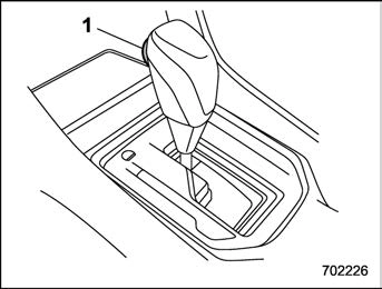
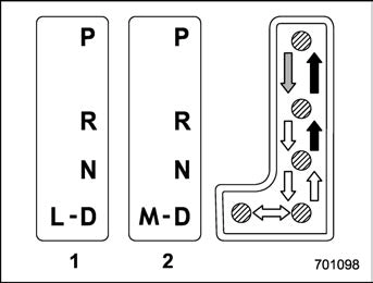
Type A
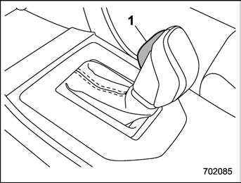
Type B
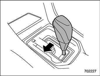
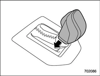
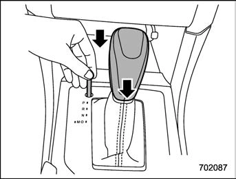
1) Select lever button
 : With the brake pedal depressed, shift while pressing the select lever button in.
 : Shift while pressing the select lever button in.
 : Shift without pressing the select lever button.
The select lever has four positions, “P”, “R”, “N”, “D” and it also has an “L” or “M” gate.
depressed hard.
! P (Park)
This position is for parking the vehicle and starting the engine. In this position, the transmission is mechanically locked to prevent the vehicle from rolling freely.
When you park the vehicle, first apply the parking brake firmly, then shift into the “P” position. Do not hold the vehicle with only the mechanical friction of the transmission.
To shift the select lever from the “P” position to any other position, you should depress the brake pedal fully then move the select lever. This prevents the vehicle from lurching when it is started.
This position is for backing the vehicle. To shift from the “N” to “R” position, stop the vehicle completely then move the lever to the “R” position while pressing the select lever button in.
When the ignition switch has been turned to the “ACC” position, the movement of the select lever from the “N” to “R” position is only possible by depressing the brake pedal. For details, refer to “Shift lock function” P322.
! N (Neutral)
This position is for restarting a stalled engine. In this position, the transmission is neutral, meaning that the wheels and transmission are not locked. Therefore, the vehicle will roll freely, even on the slightest incline unless the parking brake or foot brake is applied.
Avoid coasting with the transmission in neutral. Engine braking has no effect in this condition.
This position is for normal driving. The transmission shifts automatically and con- tinuously into a suitable gear according to the vehicle speed and the acceleration you require. Also, while driving up and down a hill, the transmission assists and controls the driving performance and engine brak- ing while corresponding to the road grade.
When more acceleration is required in the
“D” position, depress the accelerator pedal fully to the floor and hold that position. The transmission will automatically downshift. In this case, the transmission will operate like a conventional automatic transmis- sion. When you release the pedal, the transmission will return to the original gear position.
For models with manual mode, if one of the shift paddles behind the steering wheel is operated while driving in the “D” position, the transmission will temporarily switch to the manual mode. In this mode, you can shift into any gear position using the shift paddles. For details about the manual mode, refer to “Selection of manual mode”
P320. Once the vehicle speed stabi- lizes, the transmission will switch from the manual mode back to the “D” position for normal driving.
Type A
Type B
With the vehicle either moving or station- ary, move the select lever from the “D”
position to the “M” position to select the manual mode.
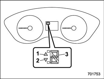
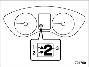
Select lever/gear position indicator (type A)
Select lever/gear position indicator (type B)
When the manual mode is selected, the gear position indicator and upshift indica- tor and/or downshift indicator on the combination meter illuminate.
The gear position indicator shows the currently selected gear in the following range.
The upshift and downshift indicators show when a gear shift is possible. When the upshift indicator “  ” illuminates, upshift- ing is possible. When the downshift in- dicator “
  ” illuminates, downshifting is
possible. When both indicators illuminate, upshifting and downshifting are both pos- sible. When the vehicle stops (for exam- ple, at traffic signals), the downshift in- dicator turns off.
Gearshifts can be performed using the shift paddle behind the steering wheel.
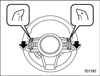
To upshift to the next higher gear position, pull the shift paddle that has “+” indicated on it. To downshift to the next lower gear position, pull the shift paddle that has “–” indicated on it.
To deselect the manual mode, return the select lever to the “D” position from the “M” position.
and let the engine idle until the warning light turns off.

Type A

Type B
“L” is for using engine braking when going down a hill, etc. To select this mode, move the select lever from the “D” position to the “L” position.
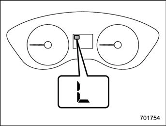
When selected, the indicator “L” will
illuminate on the combination meter.
To deselect “L”, move the select lever to the “D” position.
The shift lock function helps prevent the improper operation of the select lever.
If the select lever cannot be operated, turn the ignition switch back to the “ON” position then move the select lever to the
“P” position with the select lever button pressed and brake pedal depressed.
If the select lever does not move after performing the above procedure, perform the following steps.
Refer to “Shift lock release using the shift lock release button” P322.
After placing the ignition switch in the “ACC” position, move the select lever to the “P” position with the select lever button pressed and brake pedal depressed.
If you must perform the above procedure, the shift lock system (or the vehicle control system) may be malfunctioning. Contact a SUBARU dealer for an inspection as soon as possible.
If the select lever does not move after performing the above procedure, refer to “Shift lock release using the shift lock release button” P322.
Perform the following procedure to release the shift lock.
engine.
If the select lever does not move after performing the above procedure, the shift lock system may be malfunctioning. Con- tact a SUBARU dealer for an inspection as soon as possible.
ates or rapidly pulls away from a standstill. This phenomenon does not indicate a malfunction.
Download Manual