RAMBOX — IF EQUIPPED
The RamBox system is an integrated pickup box storage and cargo management system consisting of up to three features:
- Integrated box side storage bins
- Cargo divider (if equipped)
- Bed rail tie-down system (if equipped)
There will also be a 115 Volt (400 Watt) power inverter located in the RamBox. Refer to “Internal Equipment” in this chapter for further information.
Cargo storage bins are located on both sides of the pickup box. The cargo storage bins provide watertight, lockable, illuminated storage for up to 300 lbs (136 kg) of evenly distributed cargo.
RamBox Cargo Storage Bins
|
CAUTION! |
|
Failure to follow the following items could cause damage to the vehicle: Assure that all cargo inside the storage bins is properly secured.
Do not exceed cargo weight rating of 300 lbs (136 kg) for 2500 and 3500 series vehicles per bin.
|
To open a storage bin with the RamBox unlocked, push and release the button located on the lid. The RamBox lid will open upward to allow hand access. Lift the lid to fully open.
RamBox will not open when the button is pushed if the RamBox is locked.
RamBox Pushbutton And Lock
|
CAUTION! |
|
Leaving the lid open for extended periods of time could cause the vehicle battery to discharge. If the lid is required to stay open for extended periods of time, it is recommended that the bin lights be turned off manually using the on/off switch. |
The interior of the RamBox will automatically illuminate when the lid is opened. In addition to the automatic illumination, there is a manual on/off switch located at the rear of each storage bin. Pushing the switch once will turn off the bin lights, pushing the switch again will turn the lights back on.
RamBox Light Switch
Cargo bins feature two removable drain plugs (to allow water to drain from bins). To remove plug, pull up on the edge. To install, push the plug downward into drain hole.
Provisions are provided in the bins for cargo dividers and shelf supports. These accessories (in addition to other RamBox accessories) are available from Mopar.
Push and release the lock or unlock button on the key fob to lock and unlock all doors, the tail- gate and the RamBox (if equipped). Refer to “Keys” in this chapter for further details. The RamBox storage bins can be locked using the vehicle key. To lock and unlock the storage bin, insert the key into the keyhole on the push button and turn clockwise to lock or counter- clockwise to unlock. Always return the key to the upright (vertical) position before removing the key from the push button.
|
CAUTION! |
|
Ensure cargo bin lids are closed and latched before moving or driving vehicle.
Loads applied to the top of the bin lid should be minimized to prevent damage to the lid and latching/hinging mechanisms.
Damage to the RamBox bin may occur due to heavy/sharp objects placed in bin that shift due to vehicle motion. In order to mini- mize potential for damage, secure all cargo to prevent movement and protect inside surfaces of bin from heavy/sharp objects with appropriate padding.
|
Carefully follow these warnings to help prevent personal injury or damage to your vehicle:
|
WARNING! |
|
Always close the storage bin covers when your vehicle is unattended.
Do not allow children to have access to the storage bins. Once in the storage bin, young children may not be able to escape. If trapped in the storage bin, children can die from suffocation or heat stroke.
In an accident, serious injury could result if the storage bin covers are not properly latched.
Do not drive the vehicle with the storage bin covers open.
Keep the storage bin covers closed and latched while the vehicle is in motion.
Do not use a storage bin latch as a tie down.
|
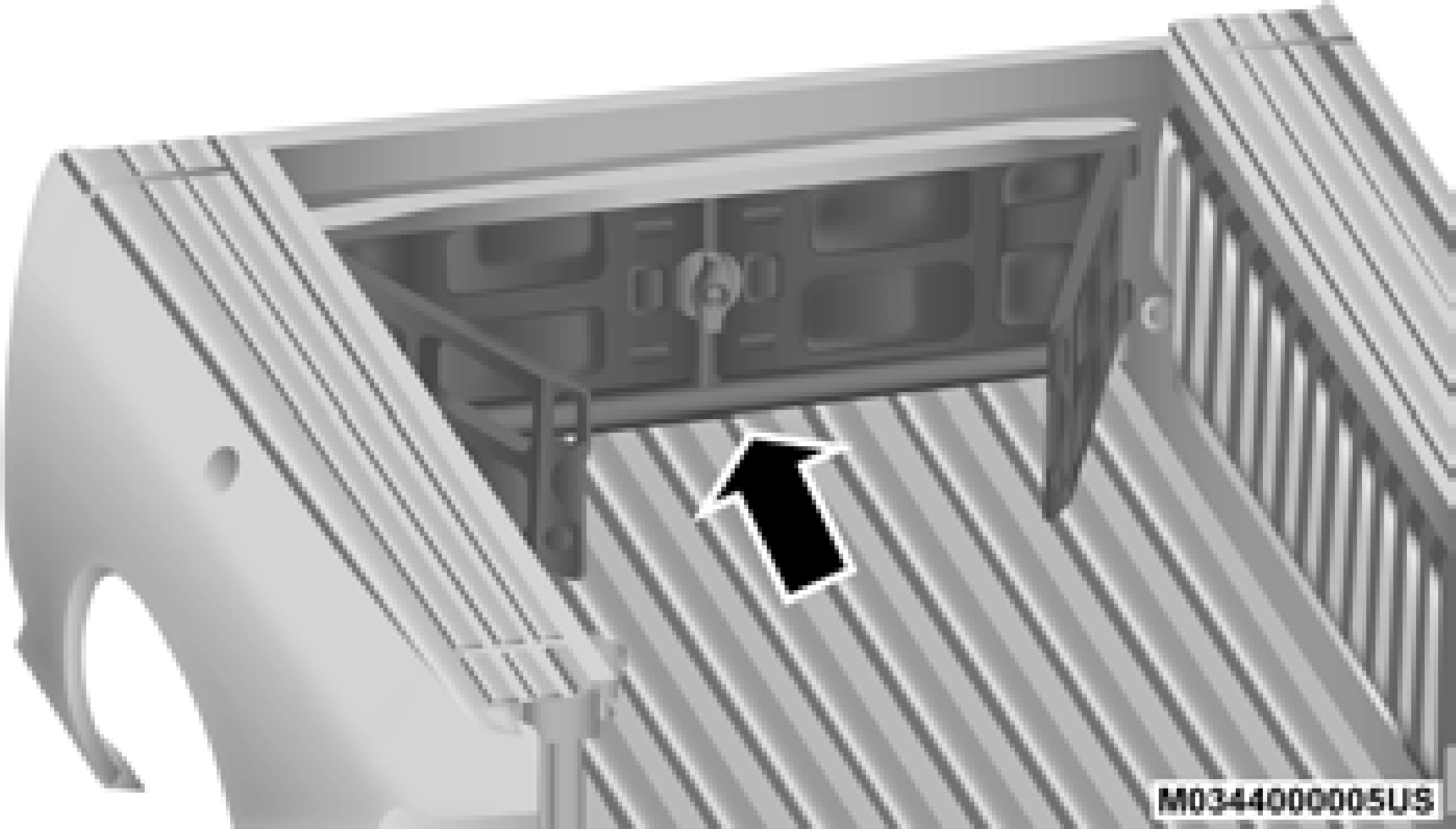
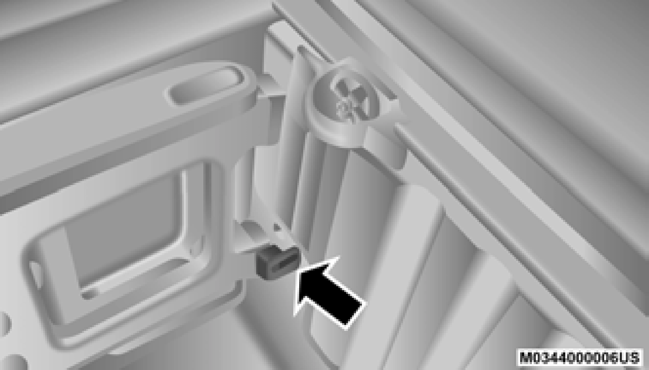
As a security measure, a Storage Bin Cover Emergency Release is built into the storage bin cover latching mechanism.
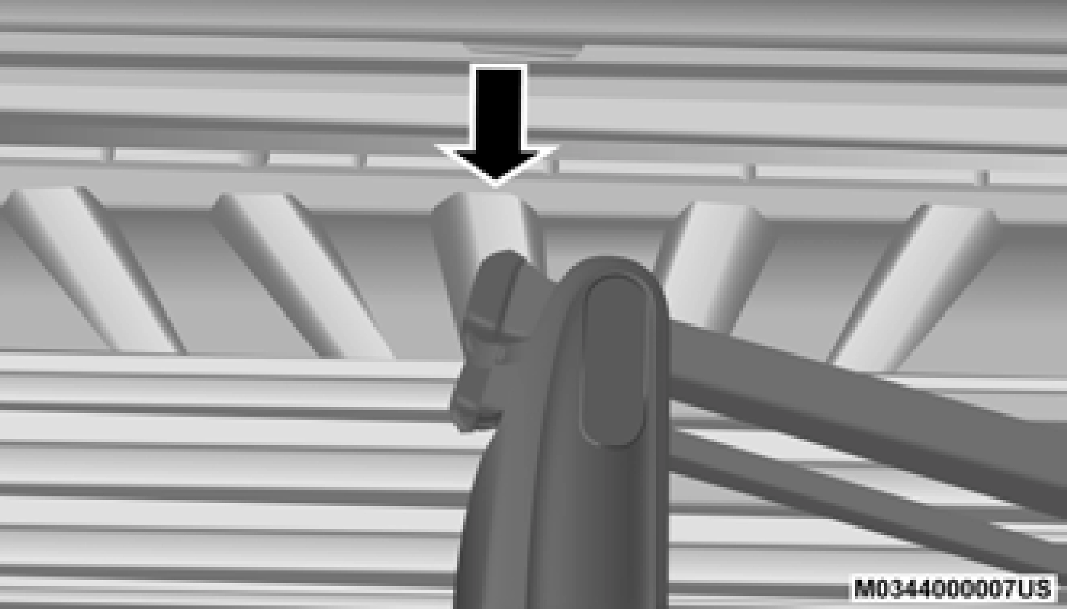
Storage Bin Cover Emergency Release Lever
In the event of an individual being locked inside the storage bin, the storage bin cover can be opened from inside of the bin by pulling on the glow-in-the-dark lever attached to the storage bin cover latching mechanism.
The bed divider has two functional positions:
- Storage Position
- Divider
The storage position for the bed divider is at the front of the truck bed which maximizes the bed cargo area when not in use.
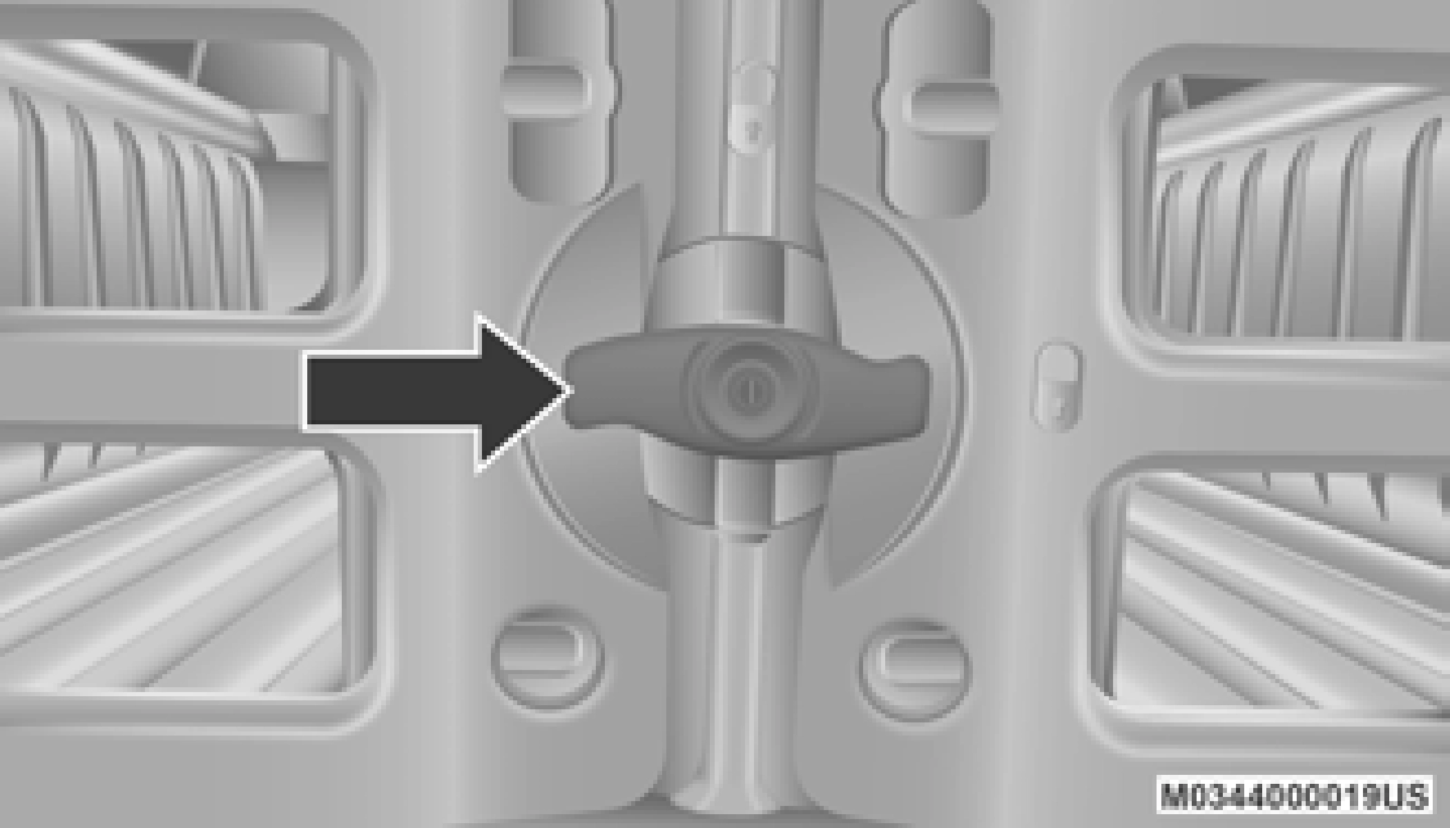
To install the bed divider into the storage posi- tion, perform the following:

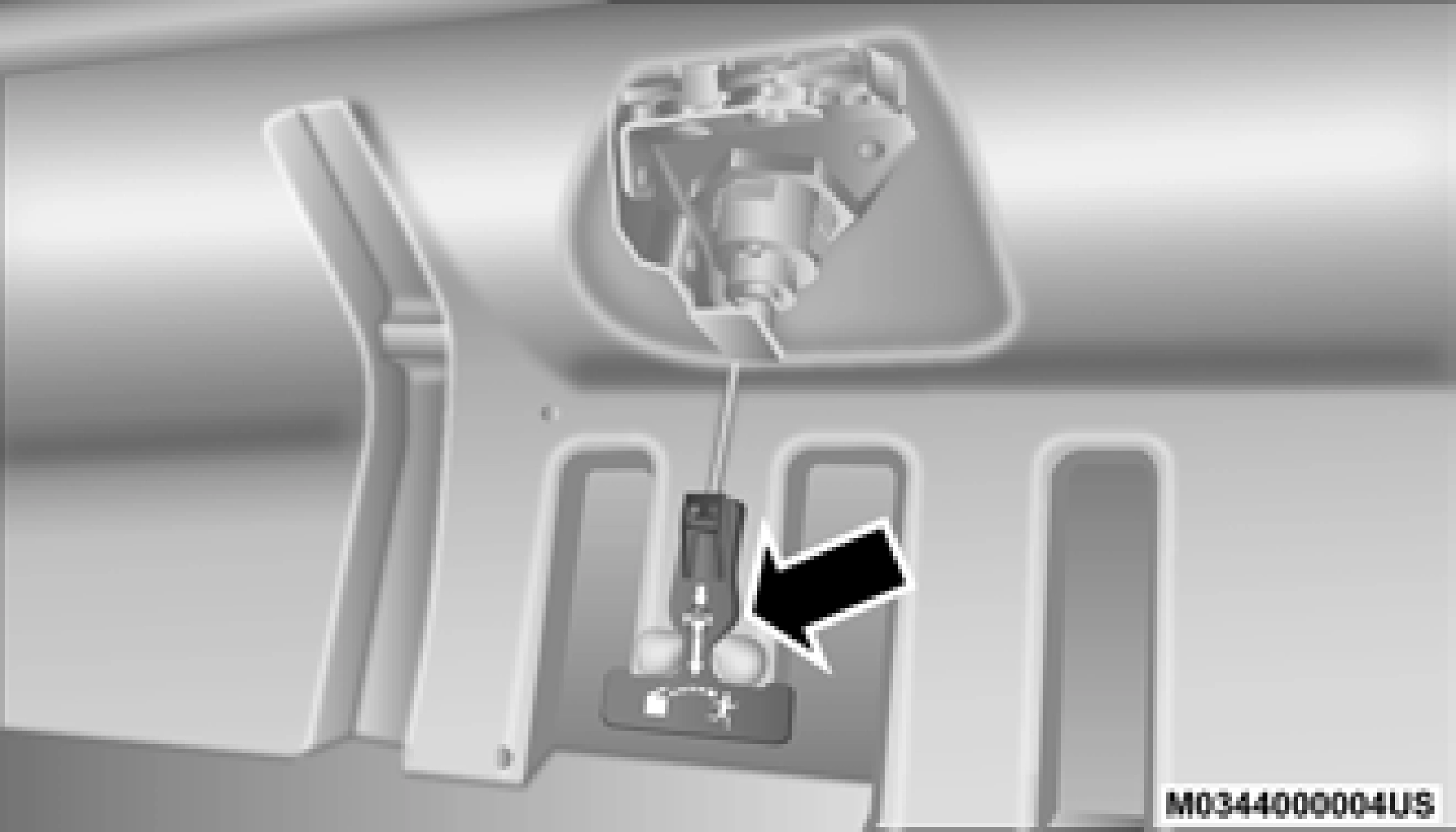
Center Handle And Lock
1 — Center Handle Lock 2 — Handle
Storage Position
Cargo Tie Down Loop
Side Gates Closed
The divider position is intended for managing your cargo and assisting in keeping cargo from moving around the bed. There are 11 divider slots along the bed inner panels which allow for various positions to assist in managing your cargo.
To install the bed divider into a divider position, perform the following:
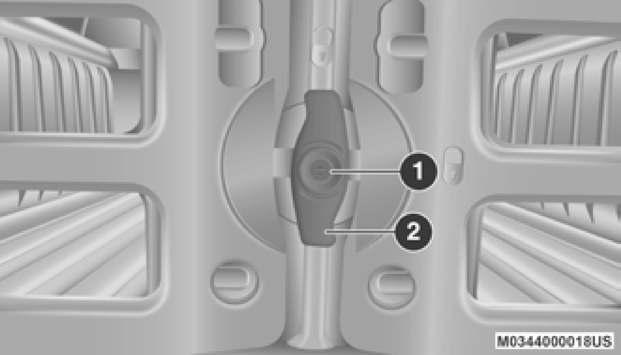
Center Handle And Lock
1 — Center Handle Lock 2 — Handle
Aligning Gate To Slots

Side Gates Closed
|
CAUTION! |
|
The maximum load per cleat should not exceed 250 lbs (113 kg) and the angle of the load on each cleat should not exceed 45 degrees above horizontal, or damage to the cleat or cleat rail may occur. |
This feature is only available for vehicles equipped with a RamBox.
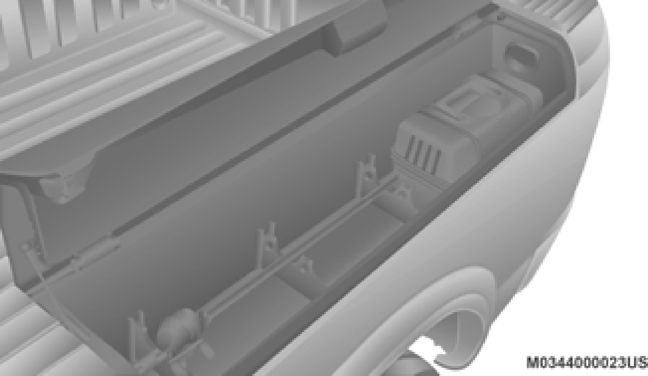
There are two adjustable cleats on each side of the bed that can be used to assist in securing cargo.
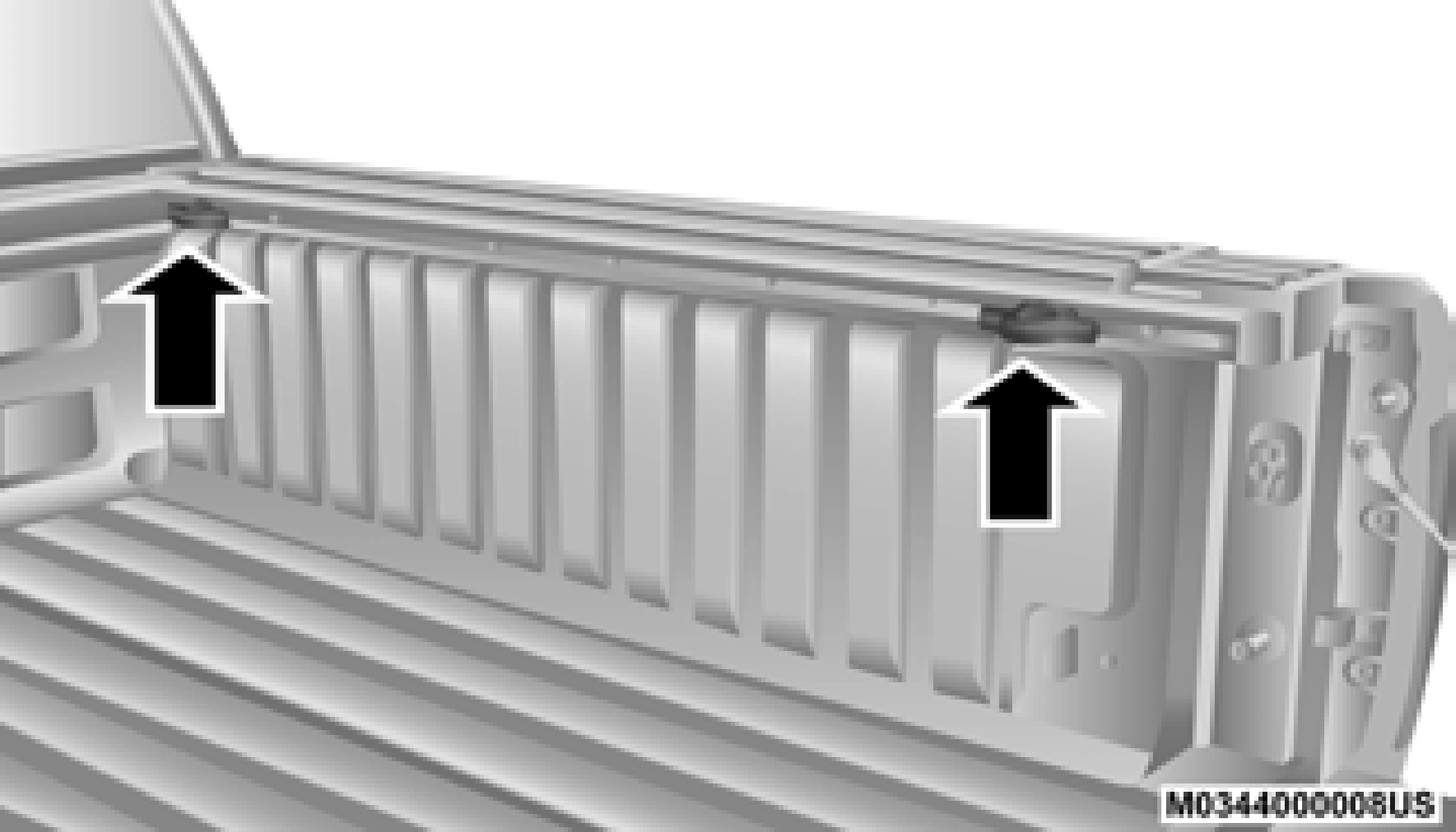
Adjustable Cleats
Each cleat must be located and tightened down in one of the detents, along either rail, in order to keep cargo properly secure.
To move the cleat to any position on the rail, turn the nut counterclockwise several turns. Then pull out on the cleat and slide it to the detent nearest the desired location. Make sure the cleat is seated in the detent and tighten the nut.
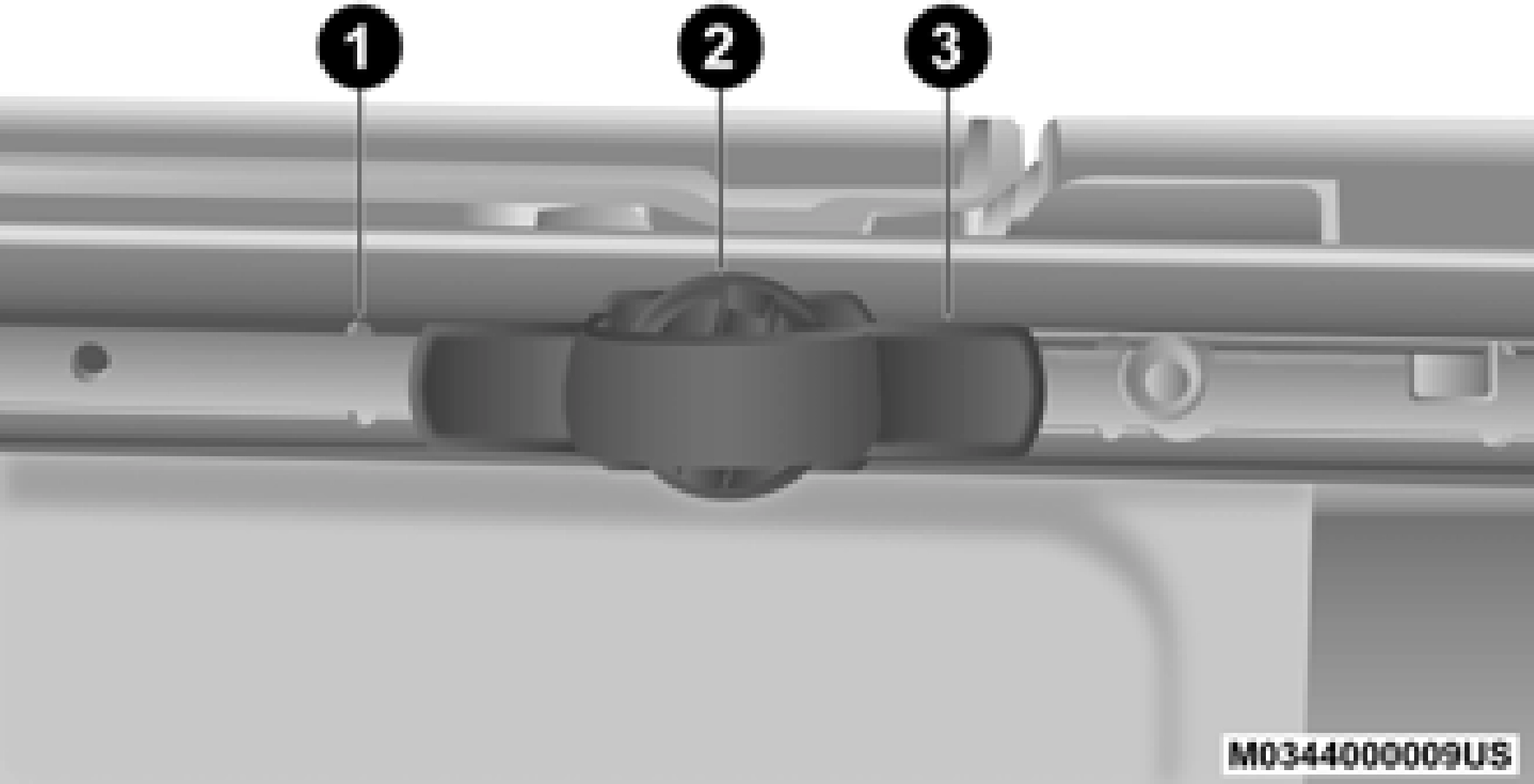
Adjustable Cleat Assembly
1 — Utility Rail Detent 2 — Cleat Retainer Nut 3 — Utility Rail Cleat
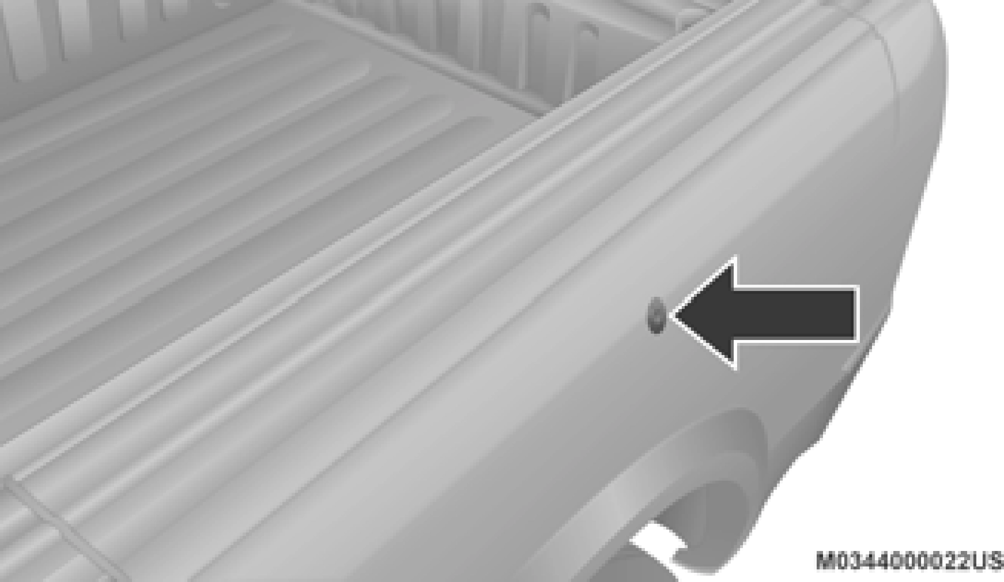
To remove the cleats from the utility rail, remove the end cap screw located in the center of the end cap, using a #T30 Torx head driver.
Remove the end cap and slide the cleat off the end of the rail.
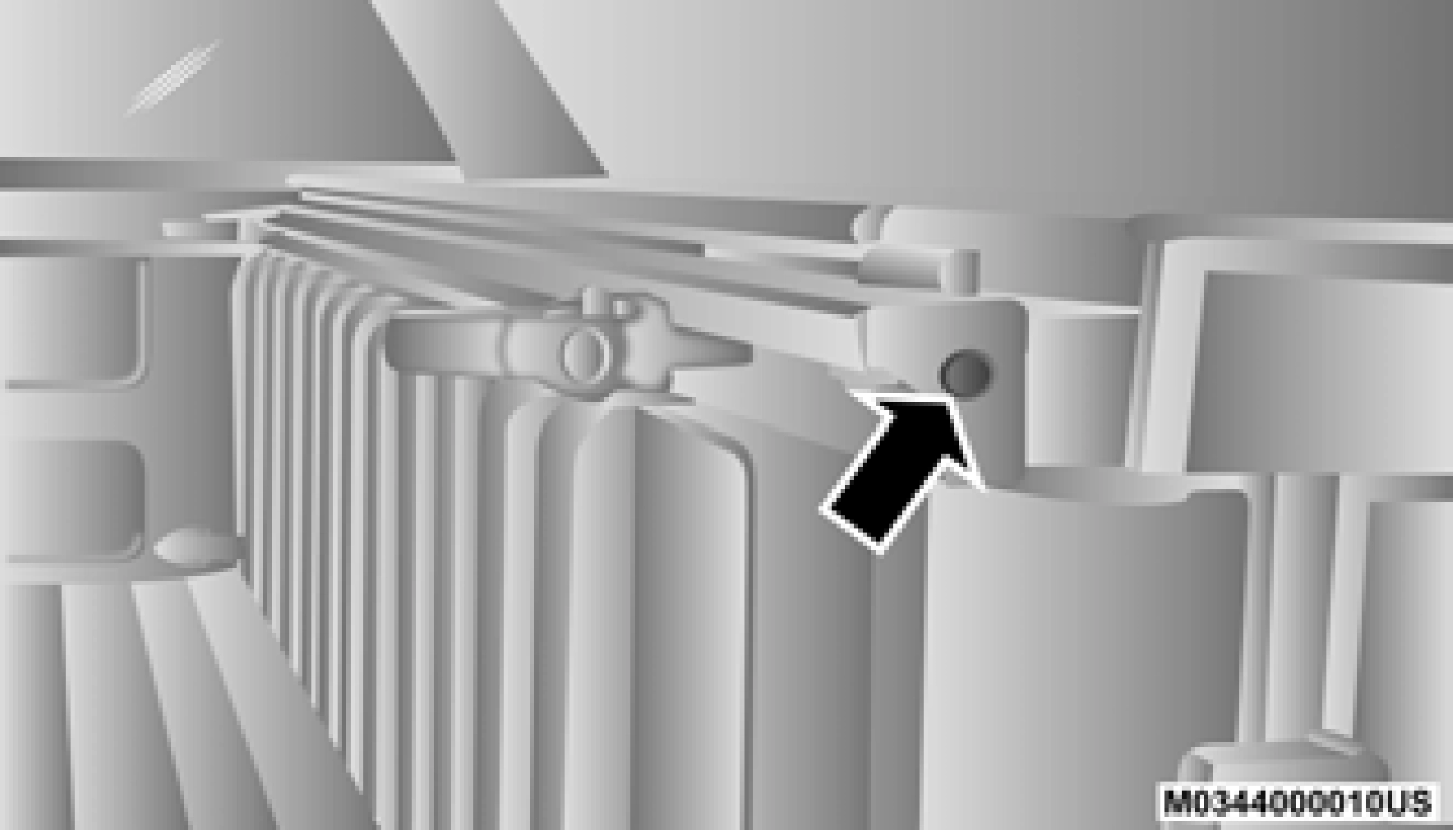
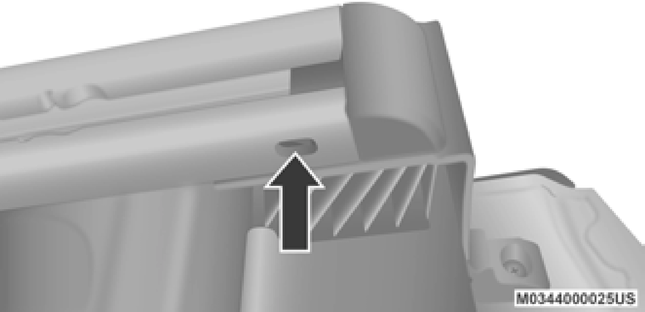
End Cap Screw Location If Equipped With Tonneau Cover
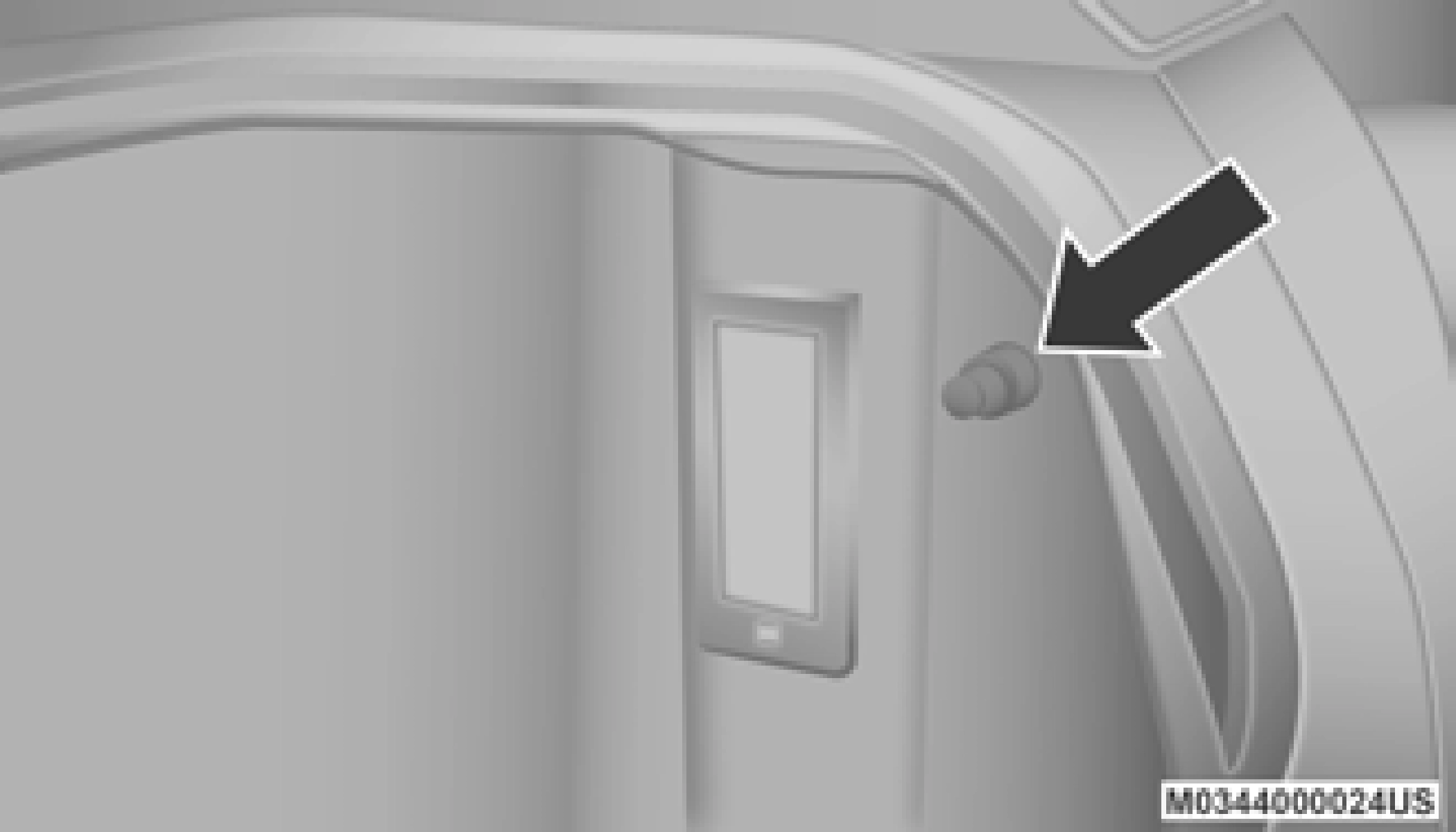
Remove the end cap by pushing upward on the release button located beneath the end cap while pulling the cap away from the rail. The cleat can now be removed by sliding it off the end of the rail.
2
End Cap Release Button If Not Equipped With Tonneau Cover
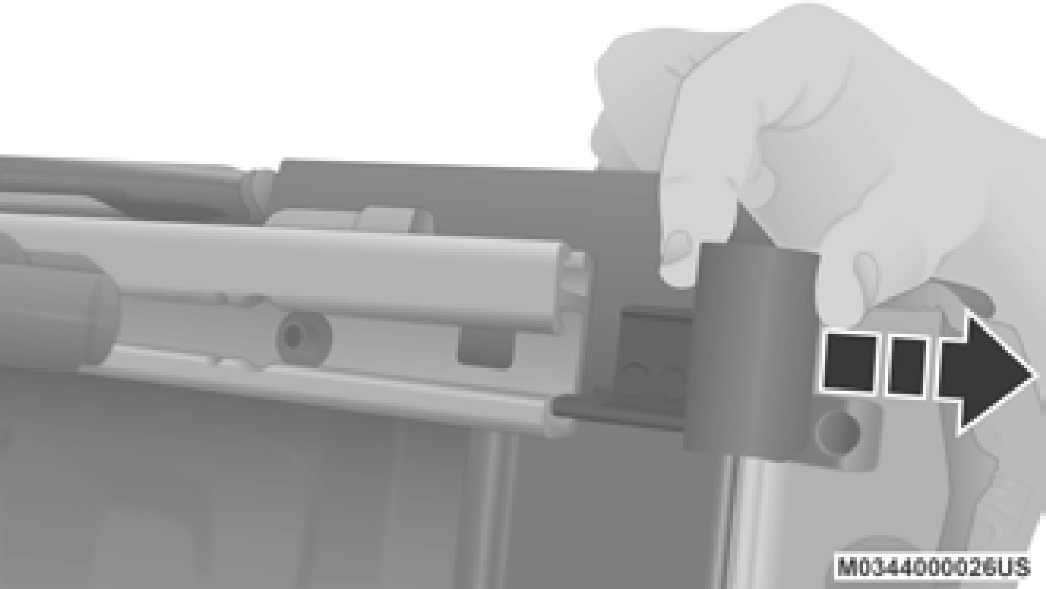
Pull End Cap Away From Rail
Download Manual