JACKING AND TIRE CHANGING
If your vehicle is equipped with an air suspension system, there is a feature which allows the automatic leveling to be disabled to assist with changing a tire.
This feature can be activated through the Uconnect system.
Refer to “Uconnect Settings” in “Multimedia” for further information.
The jack and jack tools are stored under the front passenger seat.
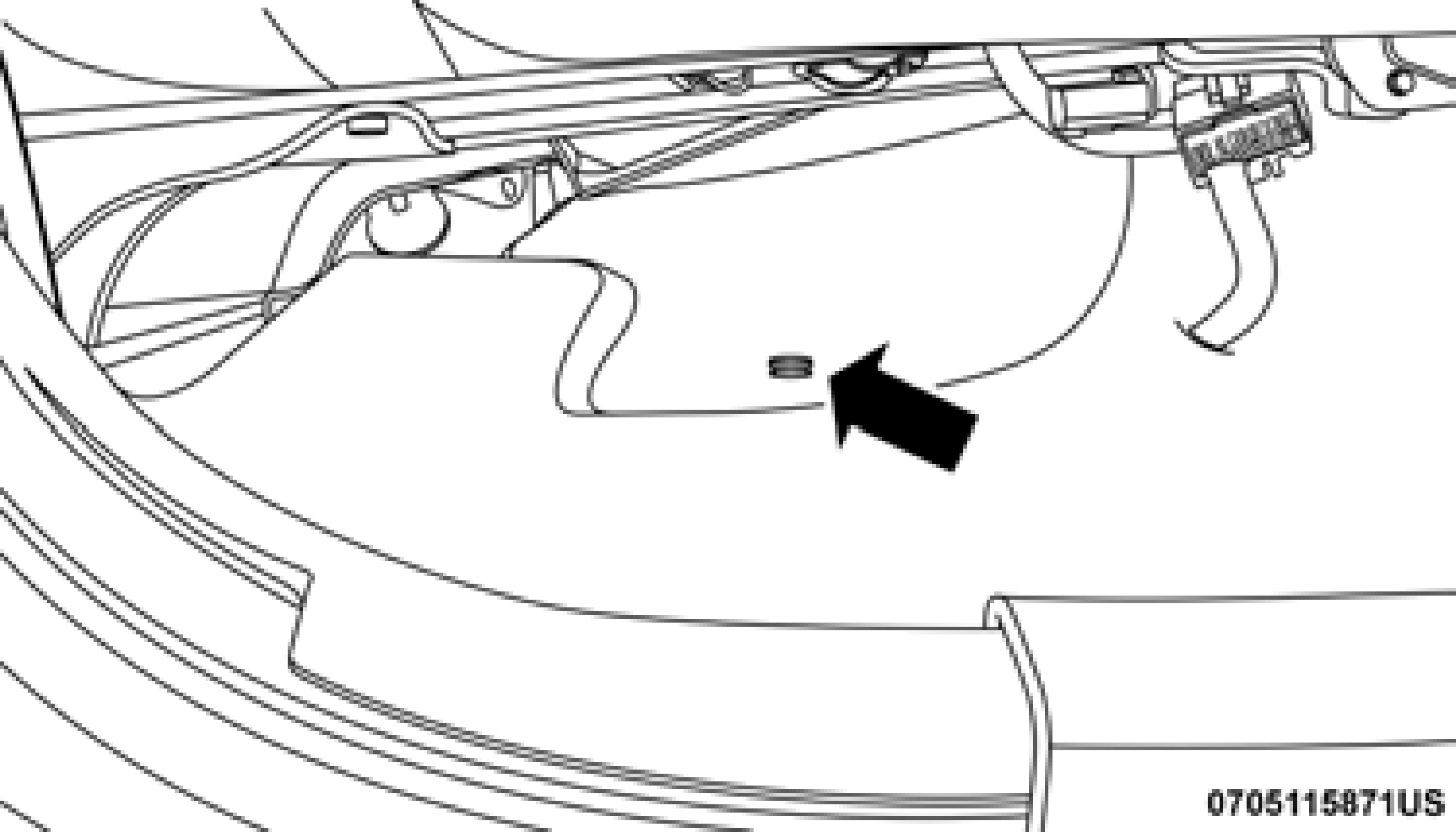
To access the jack and jack tools, you must remove the plastic access cover located on the side of the front passenger’s seat. To remove the cover, pull the front part of the cover (closest to the front of the seat) toward you to release a locking tab. Once the front of the cover is loose, slide the cover toward the front of the seat until it is free from the seat frame.
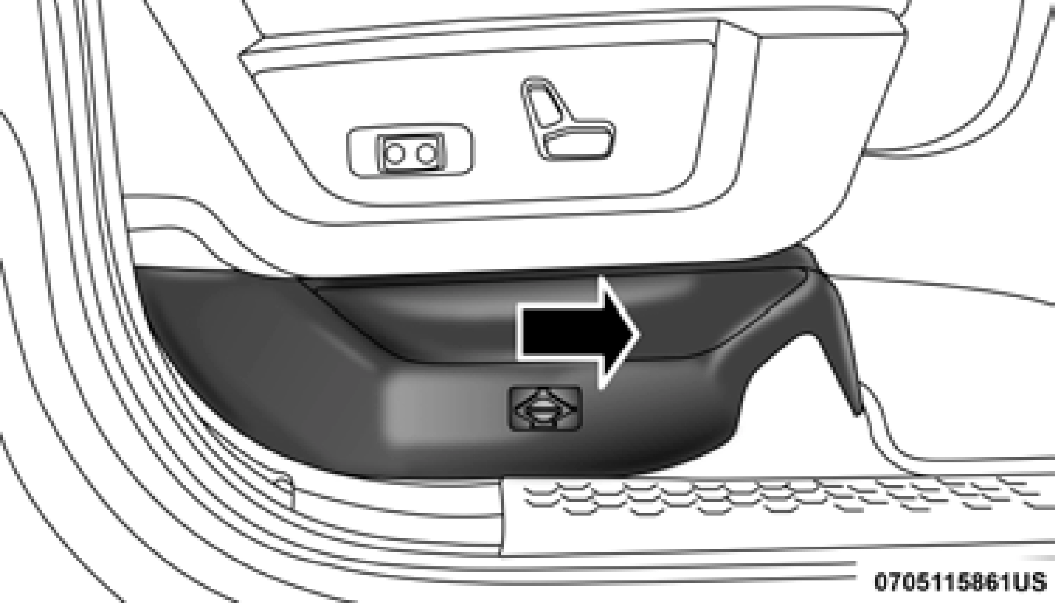
Jack Access Cover
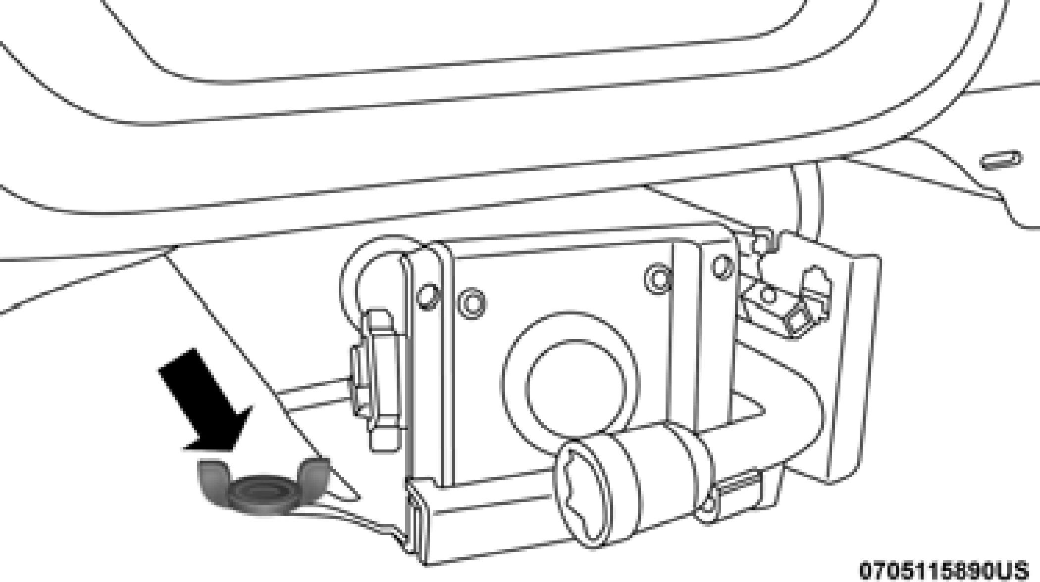
Remove the jack and tools by turning the wing bolt counter- clockwise, remove the wing bolt and then slide the assembly out from under the seat.

Wing Bolt/Jack And Tools
Remove the jack and tools from the bracket assembly. Turn the jack-turn-screw counterclockwise to release jack from bracket assembly.

Jack And Tools Bracket Assembly
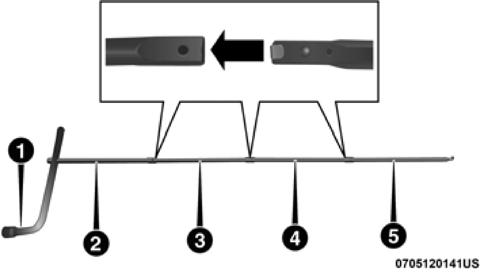
There are two ways to assemble the tools:
Assembled For Spare Tire Lowering/Raising
Assembled For Spare Tire Lowering/Raising
Assembled For Jack Operation
Assembled For Jack Operation
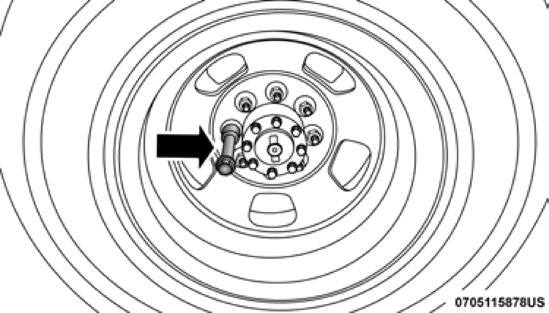
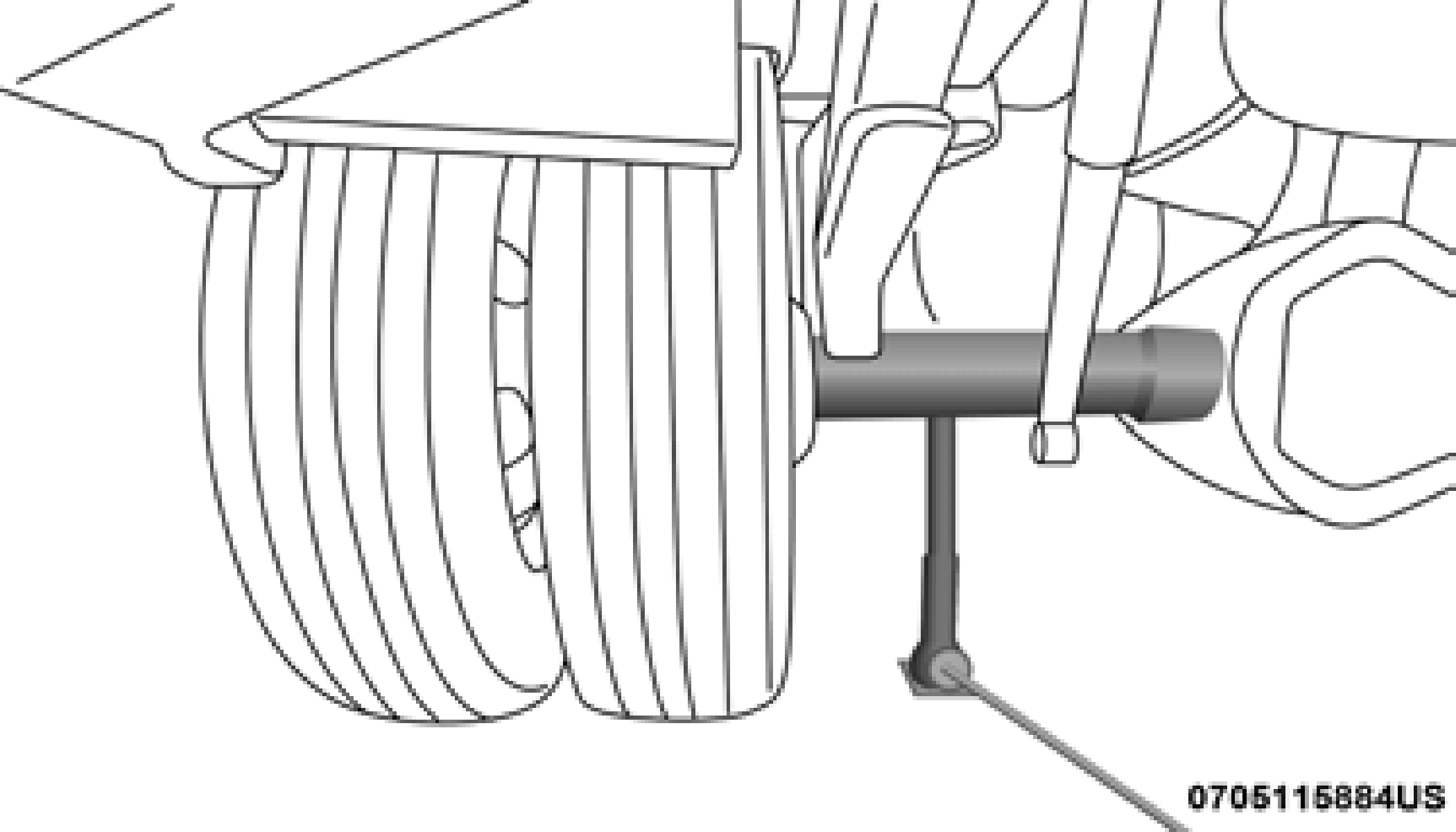
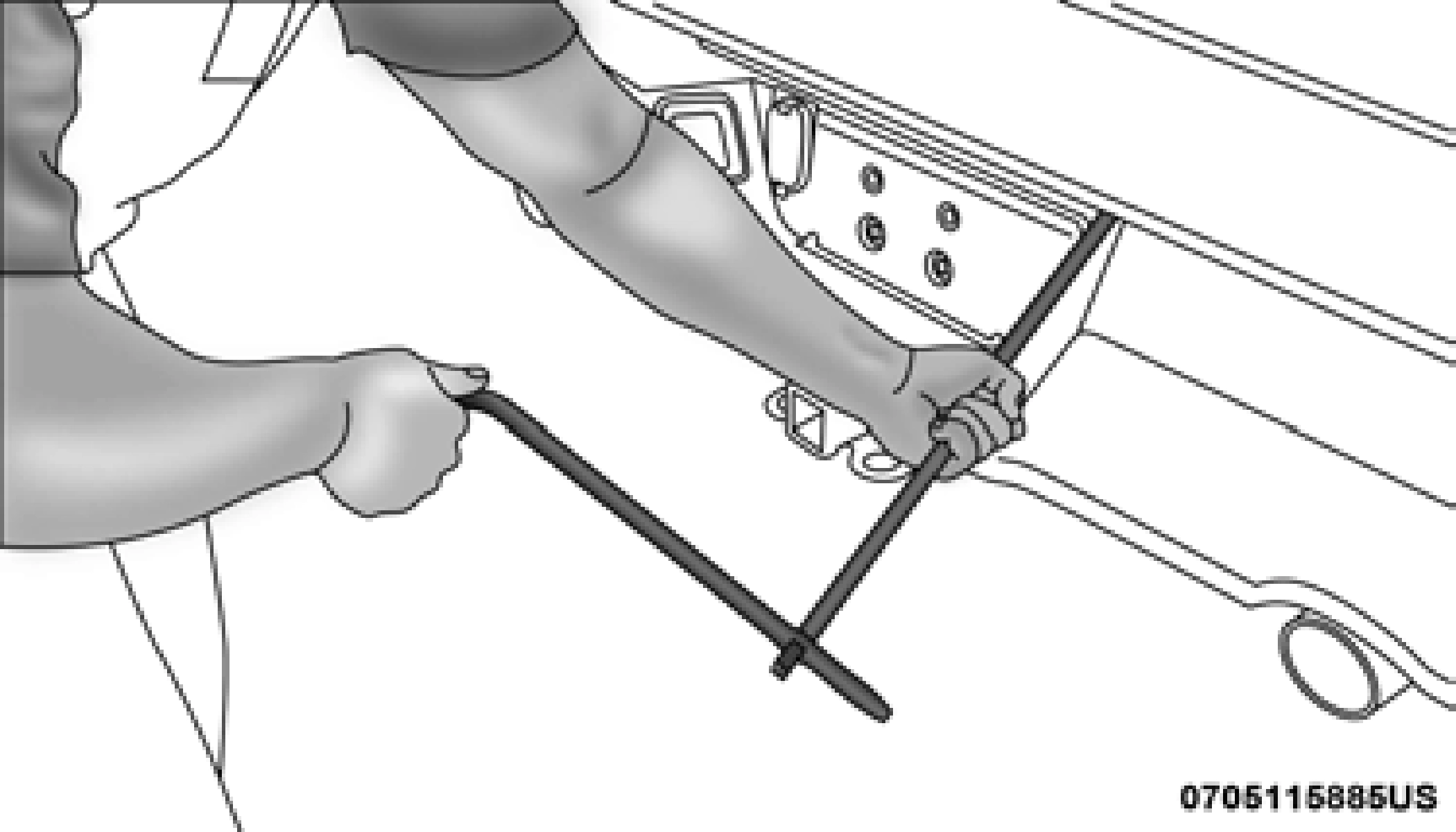
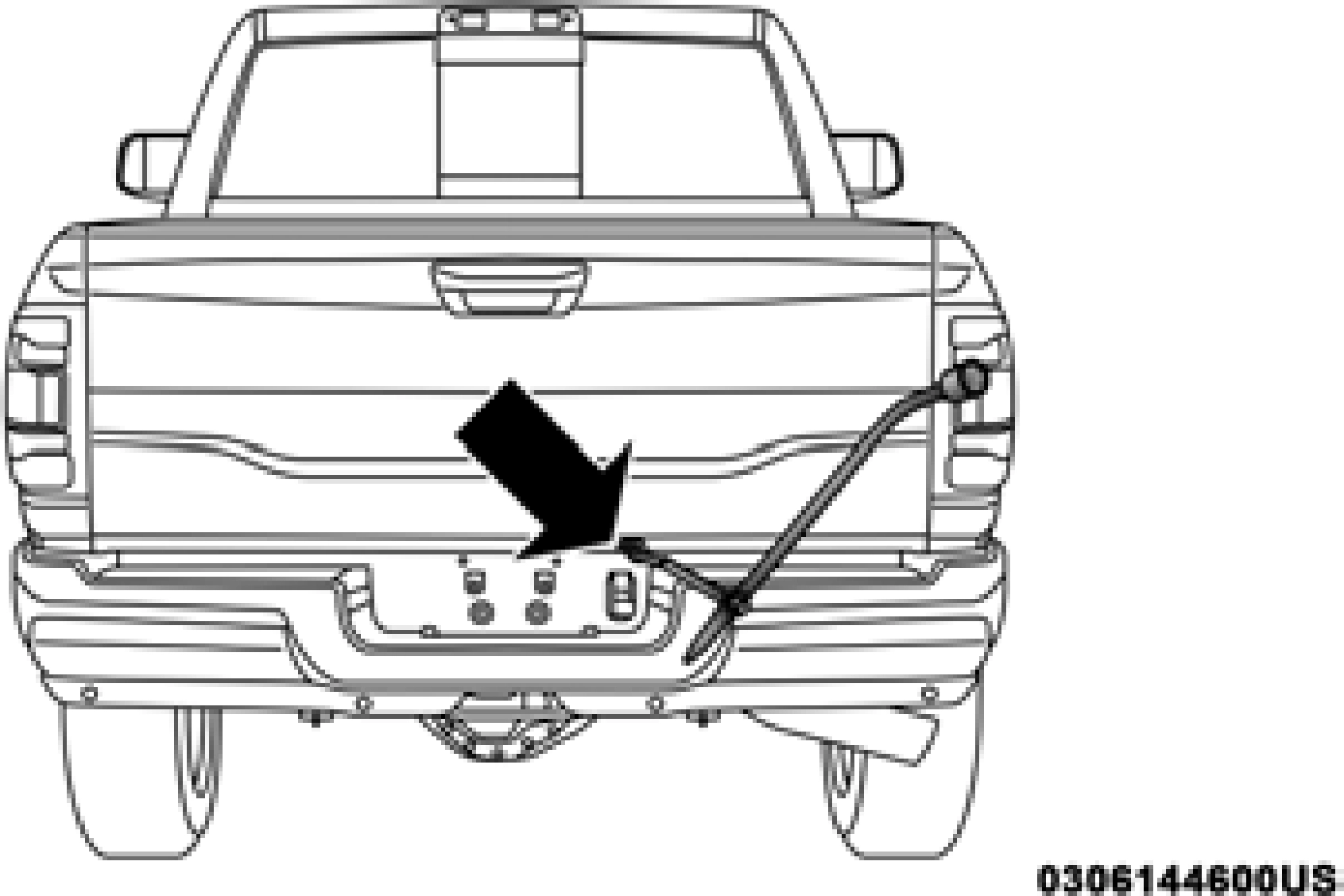 Remove the spare tire before attempting to jack up the truck. Attach the lug wrench to the extension tubes with the curved angle facing away from the vehicle. Insert the extension tube through the access hole between the lower tailgate and the top of the bumper and into the winch mechanism tube.
Inserting The Extension Tubes Into The Access Hole

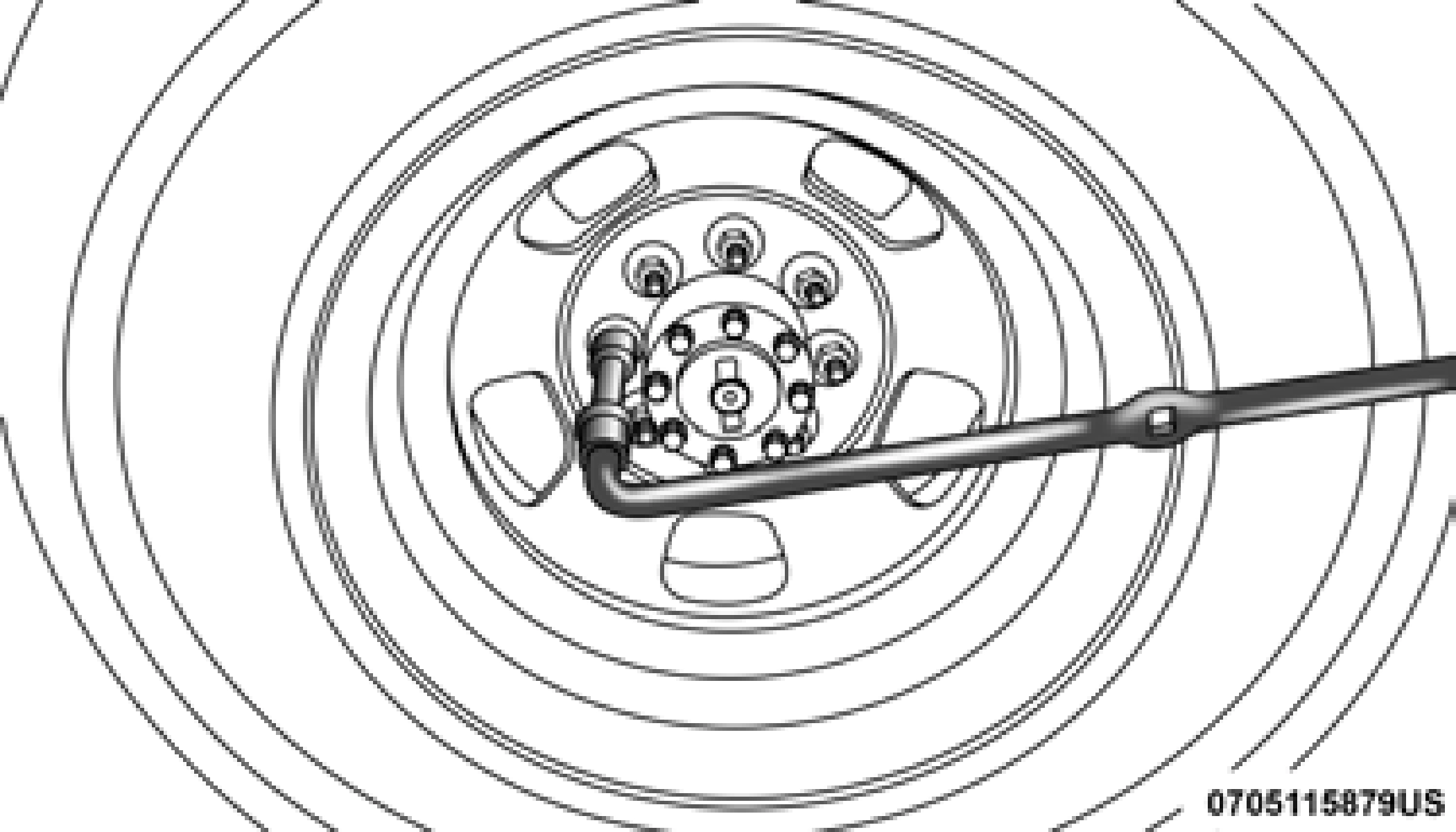
Rotating The Lug Wrench Handle

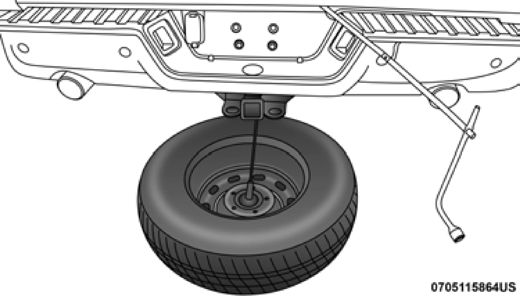
Pulling The Spare Tire Out


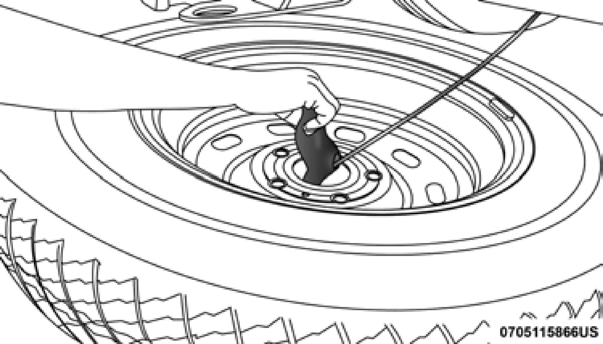
Gaining Access To The Retainer
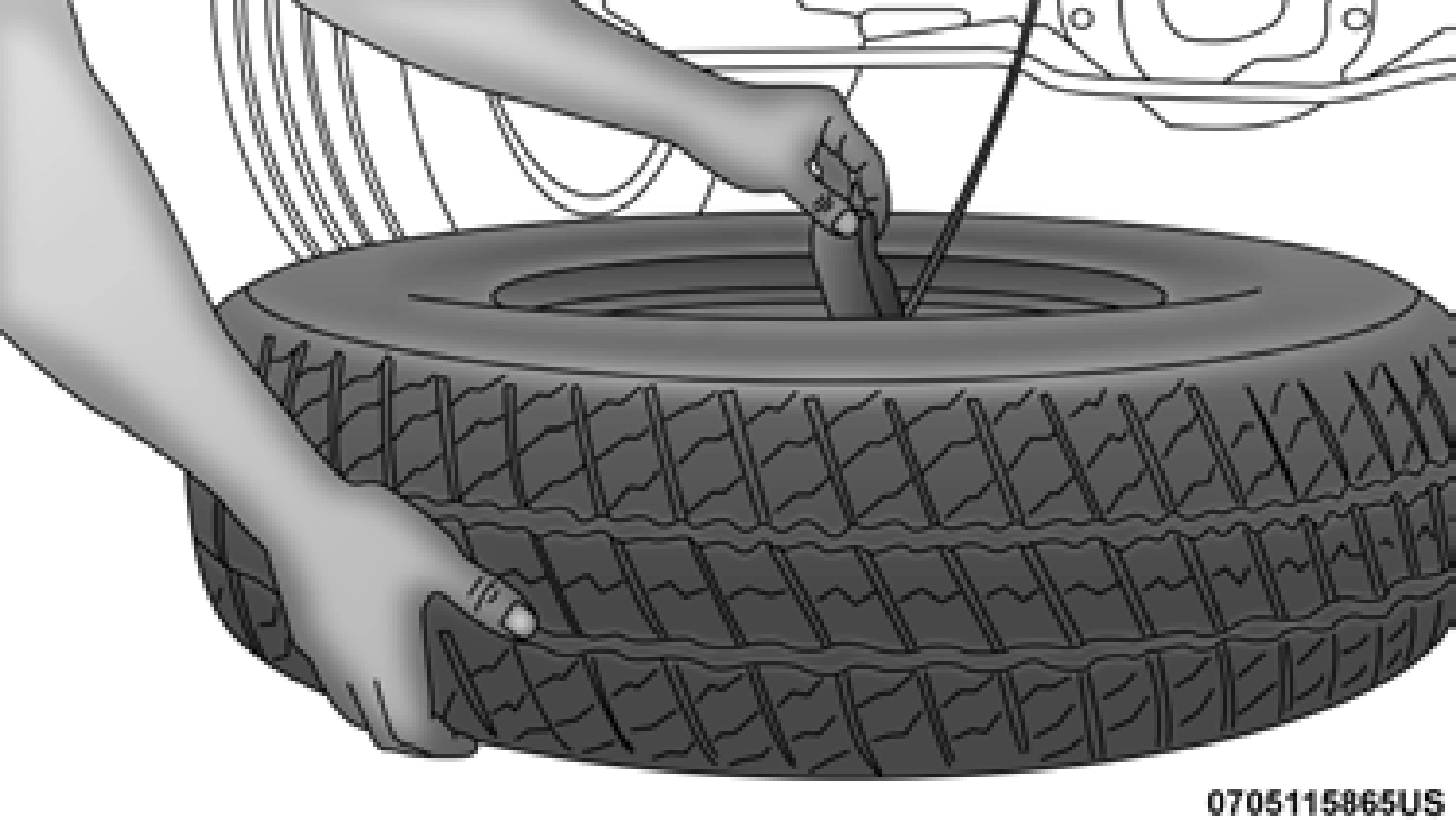
Pulling The Retainer Through The Center Of The Wheel
NOTE:
The winch mechanism is designed for use with the extension tubes only. Use of an air wrench or other power tools is not recommended and can damage the winch.
1. Park the vehicle on a firm, level surface. Avoid ice or slip- pery areas.
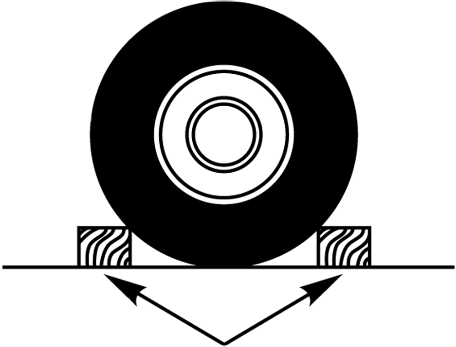
6. Block both the front and rear of the wheel diagonally opposite the jacking position. For example, if the right front wheel is being changed, block the left rear wheel.
NOTE:
Wheel Blocked
Passengers should not remain in the vehicle when the vehicle is being jacked.
WARNING!
Carefully follow these tire changing warnings to help prevent personal injury or damage to your vehicle:
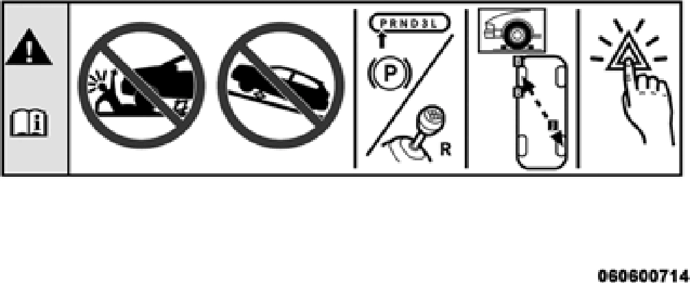
sion in PARK.
Jack Warning Label
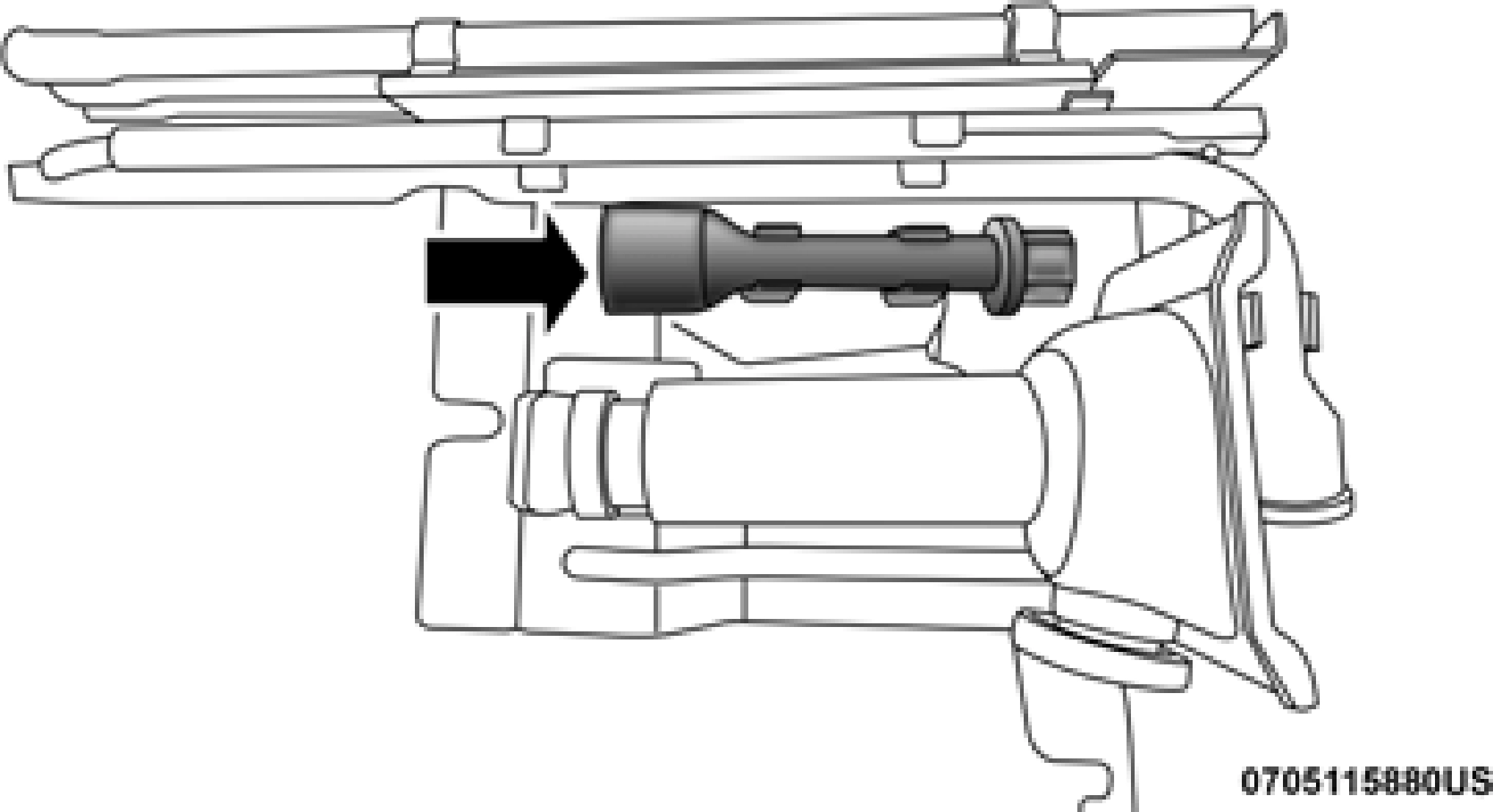
Lug Wrench Adaptor Shown In Jack And Tools Assembly
NOTE:
If your vehicle is equipped with hub caps/wheel covers they must be removed before raising the vehicle off the ground. Refer to ”Hub Caps/Wheel Covers — If Equipped” in this section.
Lug Wrench Adapter
Lug Wrench Adapter And Wrench
 6
6
Jack / Extensions Placement
Front Jacking Location
When changing the front wheel, assemble the jack driver to the jack and connect the jack driver to the extension tubes. Place the jack under the axle as close to the tire as possible with the drive tubes extending to the front. Con- nect the extension tubes and lug wrench.
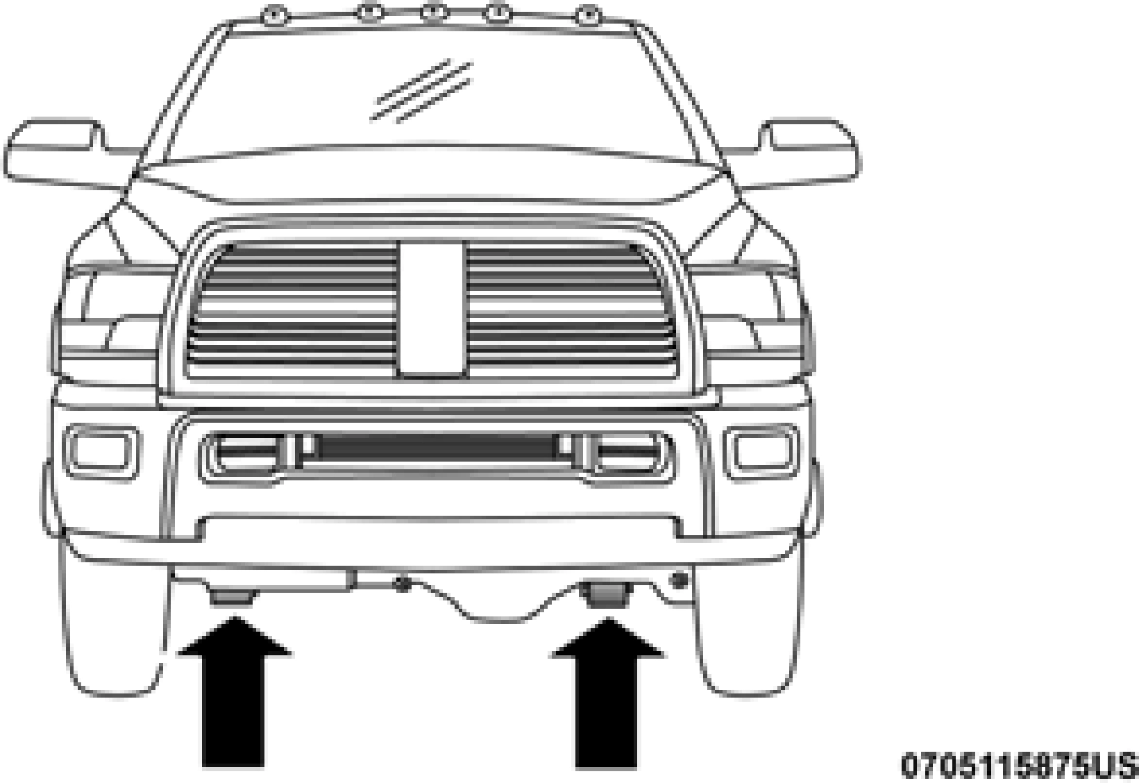
Front Jacking Location
Rear Jacking Location
When changing a rear wheel, assemble the jack driver to the jack and connect the jack driver to the extension tubes. Place the jack under the axle between the spring and the shock ab- sorber with the extension tubes extending to the rear.
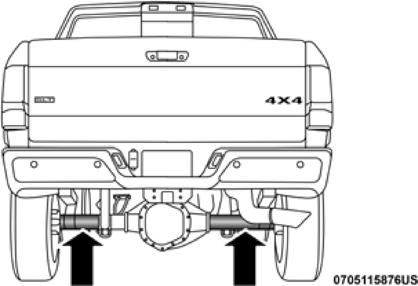
Rear Jacking Location
Connect the extension tubes and lug wrench.
NOTE:
If the bottle jack will not lower by turning the dial (thumb- wheel) by hand, it may be necessary to use the jack driver in order to lower the jack.
replaced remove the outer wheel and replace the inner wheel. The wheel nuts are a two-piece assembly with a flat face. Lightly tighten the lug nuts. To avoid the risk of forcing the vehicle off the jack, do not fully tighten the lug nuts until the vehicle has been lowered.
 6
6
Rear Inner Wheel Proper Placement (Dual Rear Wheel Equipped)
Dual Rear Wheel Jack Placement
NOTE:
The bottle jack will not lower by turning the dial (thumb- wheel) by hand, it may be necessary to use the jack driver in order to lower the jack
NOTE:
Do not oil wheel studs. For chrome wheels, do not substitute with chrome plated lug nuts.
NOTE:
Have the flat tire repaired or replaced immediately.
 6
6
Reinstalling The Retainer
Pushing The Retainer Through The Center Of The Wheel And Positioning It
Lug Wrench And Extension Tubes Assembled And In Position
 Rotate the lug wrench handle clockwise until the wheel is drawn into place against the underside of the vehicle. Continue to rotate until you feel the winch mechanism slip, or click three or four times. It cannot be overtight- ened. Push against the tire several times to ensure it is firmly in place.
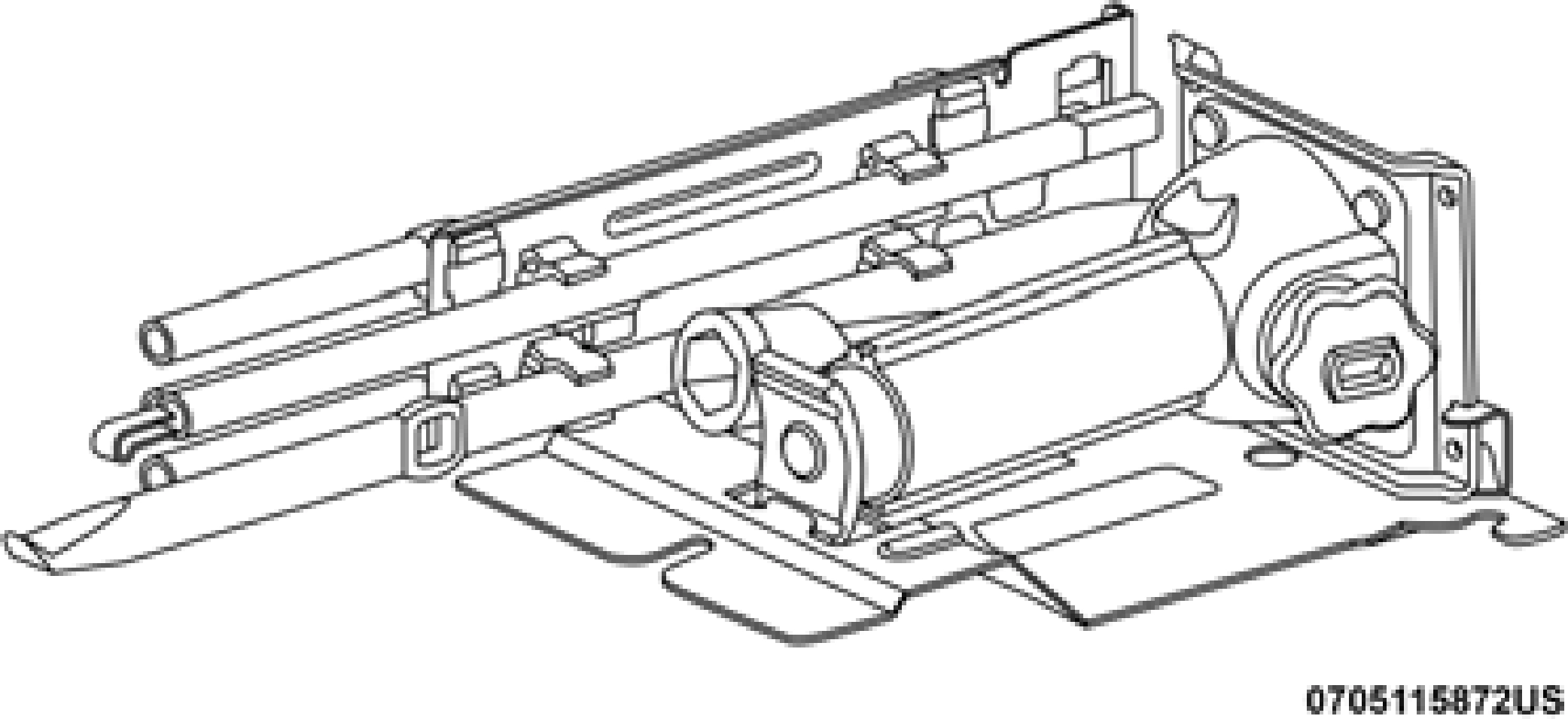
Rotating The Lug Wrench Handle
NOTE:
The winch mechanism is designed for use with the jack extension tube only. Use of an air wrench or other power tools is not recommended and can damage the winch.
Jack And Tools Bracket Assembly
Wing Bolt/Jack And Tools
Jack Hold Down Fastener
NOTE:
Ensure that the jack and tool bracket assembly slides into the front hold down location.
The hub caps must be removed before raising the vehicle off the ground.
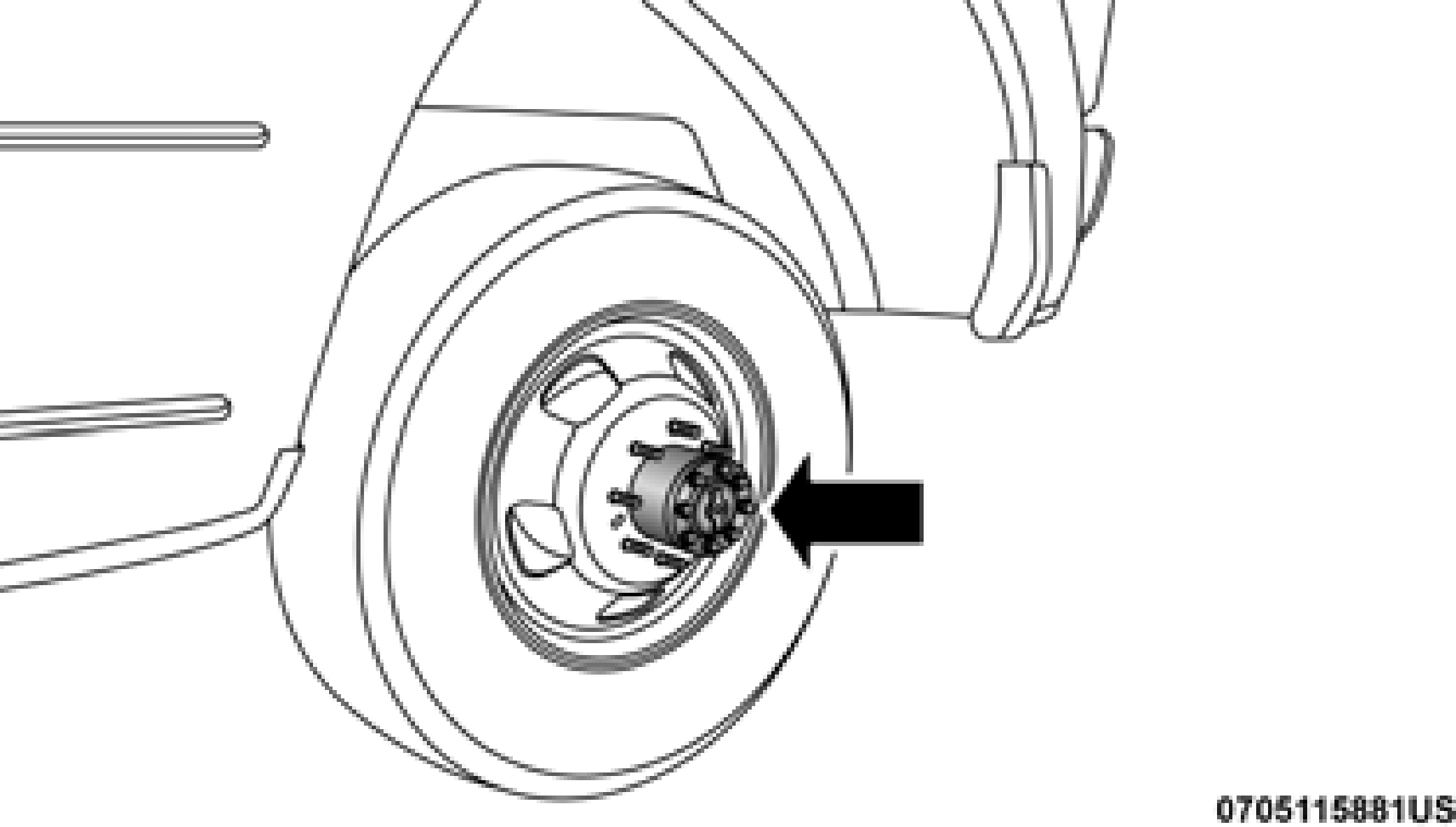
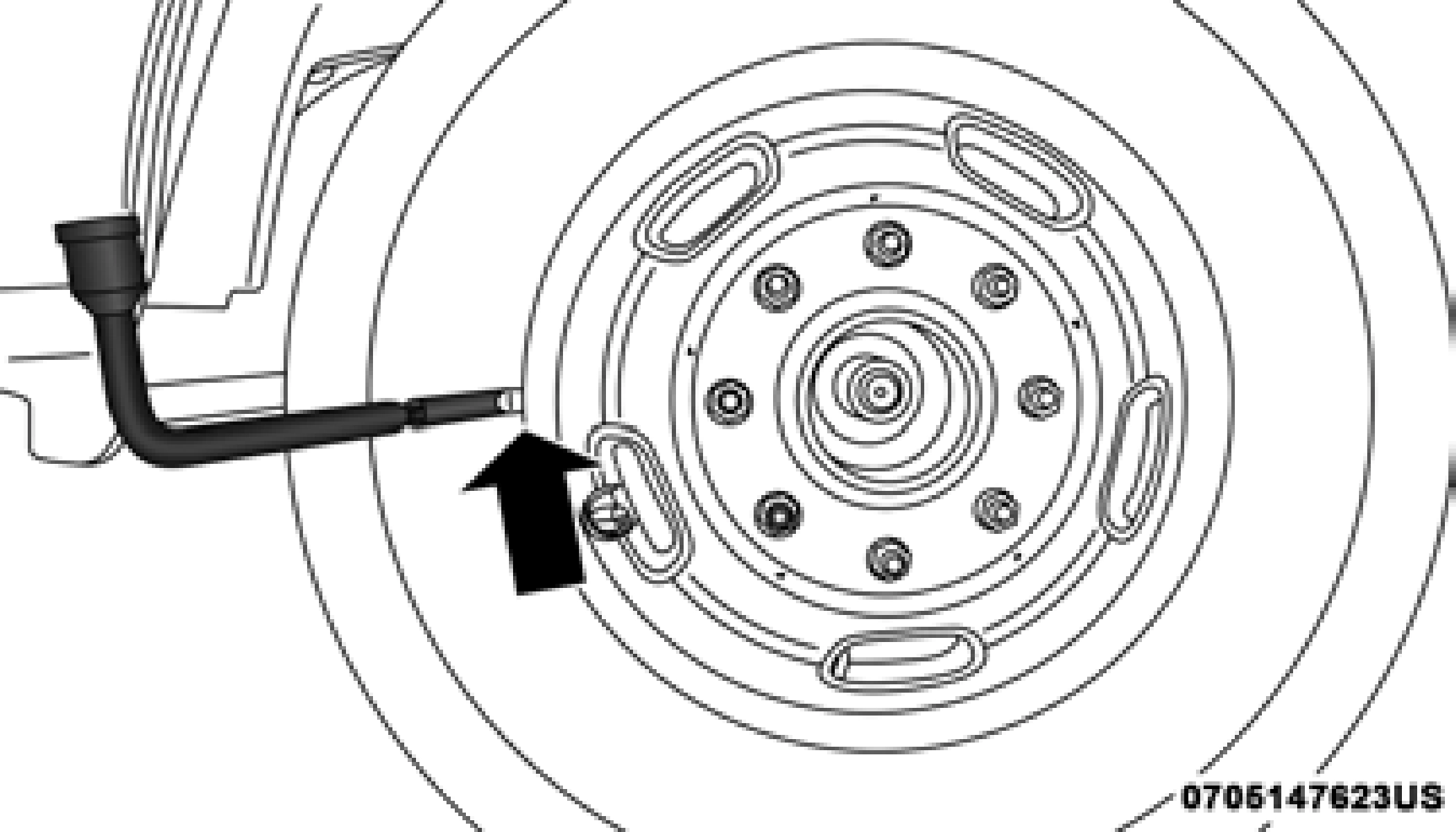
For 2500/3500 single rear wheel (SRW) models, use the flat
Lug Wrench Insertion Location — Hub Cap 6
end of the lug wrench to hook and pull off the hub cap. Find the opening in the hub cap, insert the lug wrench, and pull off the cap. If you need to pry against the wheel, protect the wheel surface.
On 3500 models with dual rear wheels (DRW), you must first remove the hub caps—use the procedure noted for the single rear wheel. For the wheel covers (wheel skins), insert the flat end of the lug wrench between the outer edge of the wheel cover and the wheel. Pry against the wheel to remove the wheel cover. Repeat this procedure around the wheel until the cover pops off.
Lug Wrench Insertion Location — Wheel Cover
Replace the wheel covers using a rubber mallet to ease the installation. Align the wheel cover vent holes to the wheel
vent holes. Tap on the wheel cover as needed to firmly seat it evenly around the wheel.
Download Manual