VEHICLE MAINTENANCE
An authorized dealer has the qualified service personnel, special tools, and equipment to perform all service operations in an expert manner. Service Manuals are available which include detailed service information for your vehicle. Refer to these Service Manuals before attempting any procedure yourself.
Intentional tampering with emissions control systems may void your warranty and could result in civil penalties being assessed against you.
8
ENGINE OIL — GAS ENGINE
Engine Oil Selection — Gasoline Engine For best performance and maximum protection under all types of operating conditions, FCA only
recommends engine oils that are API Certified
and meet the requirements of FCA Material Standard MS-6395.
Hemi engines (5.7L) at times can tick right after startup and then quiet down after approxi- mately 30 seconds. This is normal and will not harm the engine. This characteristic can be caused by short drive cycles. For example, if the vehicle is started then shut off after driving a short distance. Upon restarting, you may experi- ence a ticking sound. Other causes could be if the vehicle is unused for an extended period of time, incorrect oil, extended oil changes or extended idling. If the engine continues to tick or if the Malfunction Indicator Light (MIL) comes on, see the nearest authorized dealer.
Engine Oil Selection — Diesel Engine
For best performance and maximum protection under all types of operating conditions, FCA recommends engine oils that meet the requirements of FCA Material Standard
MS-12991, and that are API SN certified and meet the requirements of FCA LLC.
 This symbol means that the oil has been certified by the American Petroleum Institute (API). The manufacturer only recommends API Certified engine oils.
This symbol certifies 0W-20, 5W-20, 0W-30, 5W-30 and 10W-30 engine oils.
You may use synthetic engine oils provided the recommended oil quality requirements are met, and the recommended maintenance intervals for oil and filter changes are followed.
Synthetic engine oils which do not have both the engine oil certification mark and the correct SAE viscosity grade number should not be used.
FCA strongly recommends against the addition of any additives (other than leak detection dyes) to the engine oil. Engine oil is an engineered product and its performance may be impaired by supplemental additives.
Care should be taken in disposing of used engine oil and oil filters from your vehicle. Used oil and oil filters, indiscriminately discarded, can present a problem to the environment. Contact an authorized dealer, service station or governmental agency for advice on how and where used oil and oil filters can be safely discarded in your area.
ENGINE OIL FILTER
The engine oil filter should be replaced with a new filter at every engine oil change.
A full-flow type disposable oil filter should be used for replacement. The quality of replacement filters varies considerably. Only high quality Mopar certified filters should be used.
ENGINE AIR CLEANER FILTER
For the proper maintenance intervals
page 395.
Be sure to follow the “Severe Duty Conditions” maintenance interval if applicable.
The quality of replacement filters varies considerably. Only high quality Mopar certified filters should be used.
Inspect engine air cleaner filter for dirt and or debris, if you find evidence of either dirt or debris you should change your engine air cleaner filter.
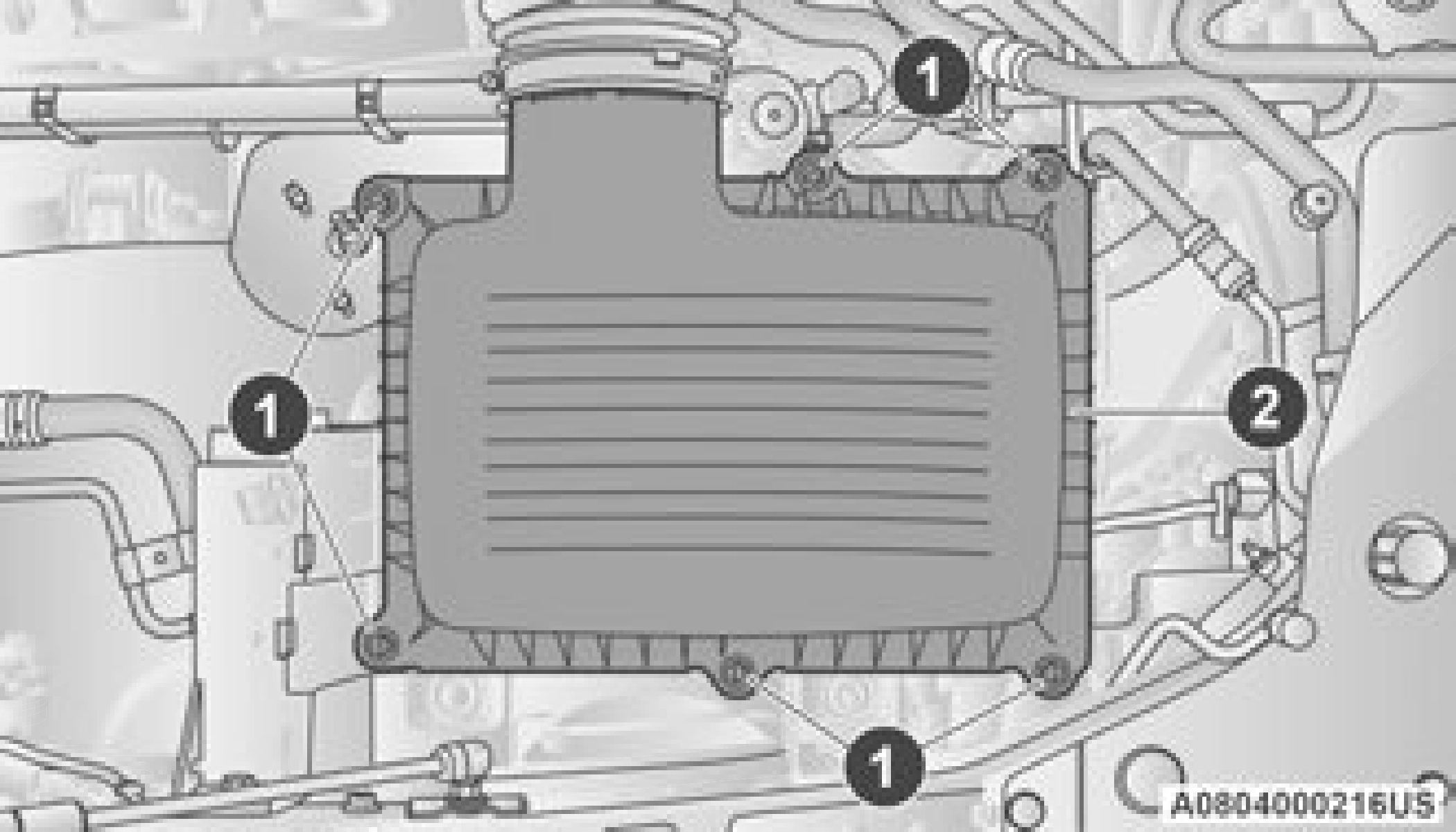
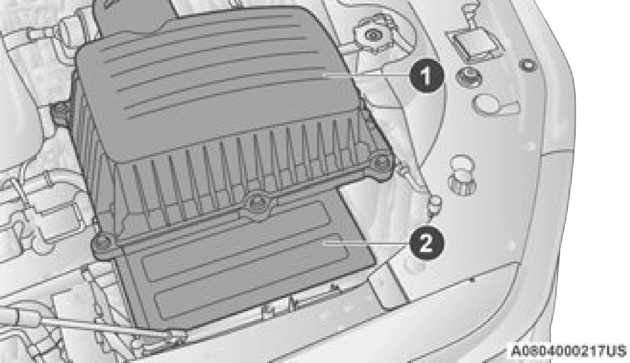
Engine Air Cleaner Filter 1 — Engine Air Cleaner Filter Cover 2 — Engine Air Cleaner Filter
8
Inspect and clean the housing if dirt or debris is present before replacing the engine air cleaner filter.
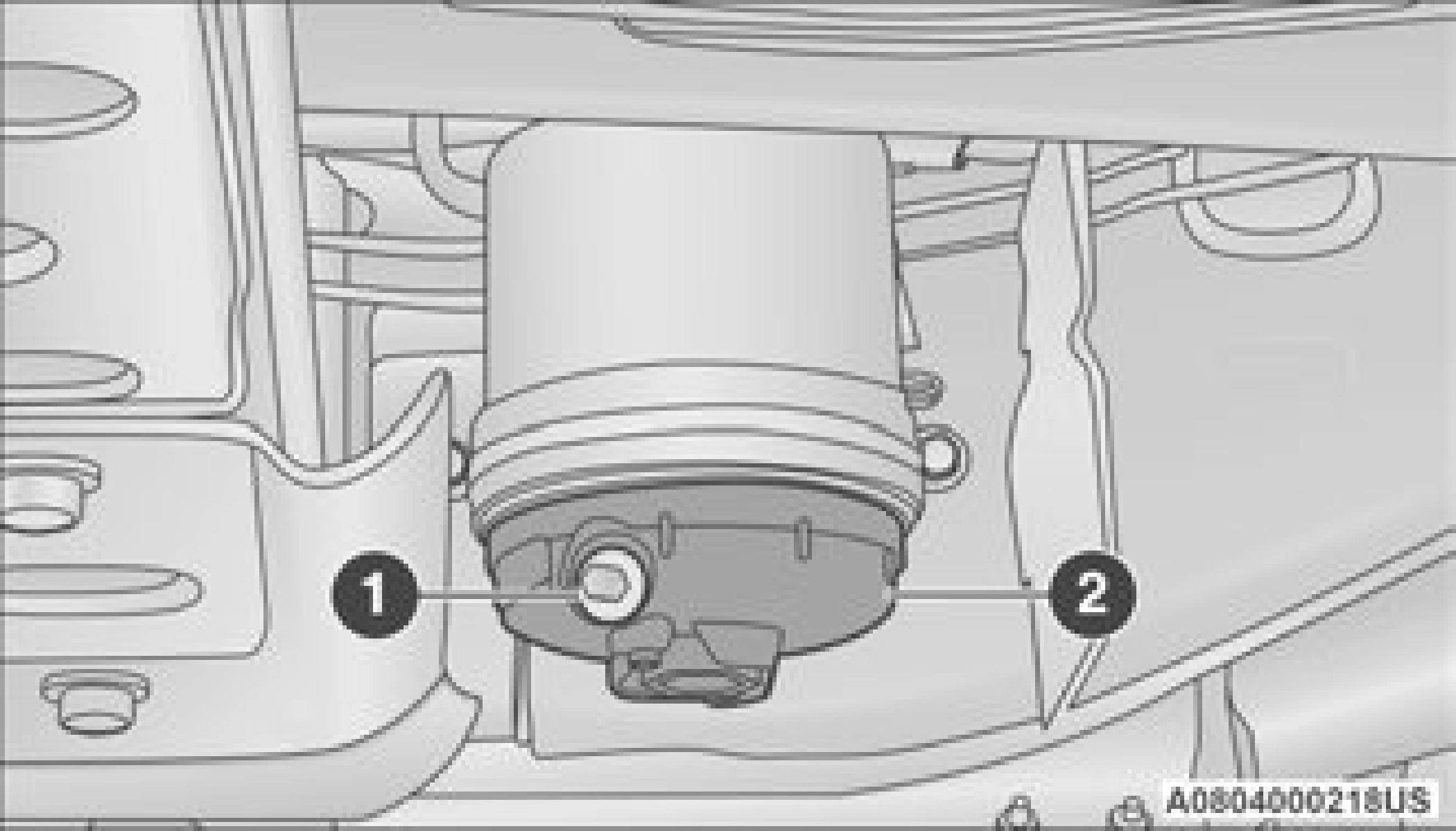
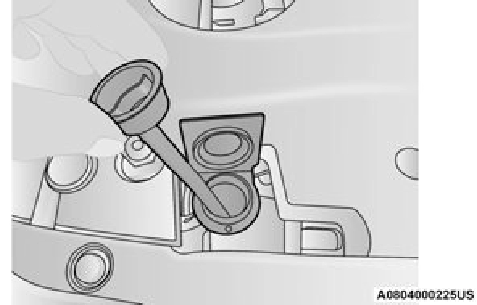
DRAINING FUEL/WATER SEPARATOR FILTER — DIESEL ENGINE
The fuel/water separator filter housing is located inside the frame rail, behind the left front wheel. The best access to this water drain valve is from under the vehicle.
(Continued)
If water is detected in the water separator while the engine is running, or while the ignition switch is in the ON/RUN position, the “Water In Fuel Indicator Light” will illuminate and an audible chime will be heard. At this point, you should stop the engine and drain the water from the filter housing.
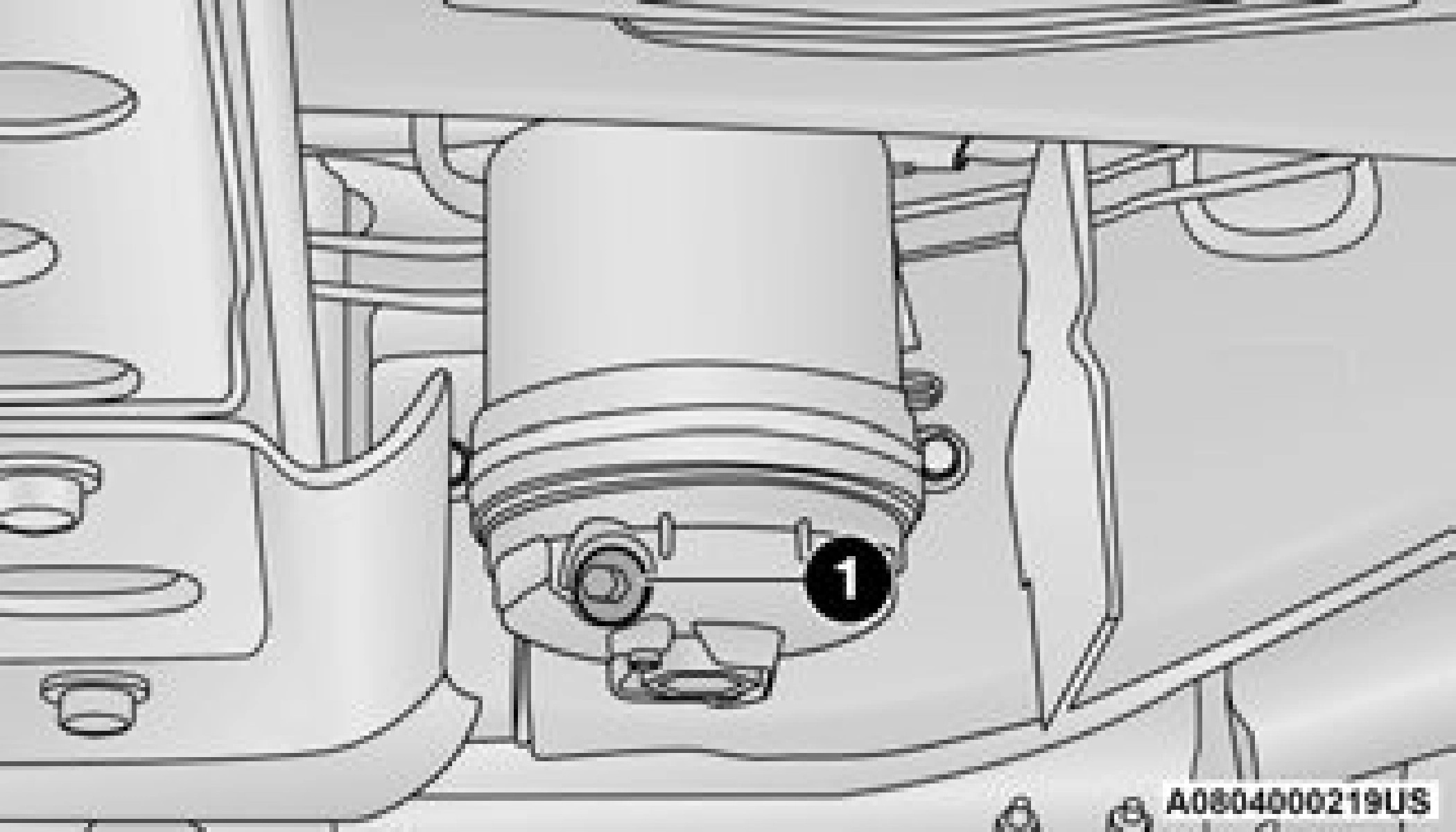
1 — Water In Fuel Drain Valve
If the “Water In Fuel Indicator Light” comes on and a single chime is heard while you are driving, or with the ignition in the ON position, there may be a problem with your water separator wiring or sensor. See an authorized dealer for service.
Upon proper draining of the water from the fuel filter, the “Water In Fuel Indicator Light” will remain illuminated for approximately 10 seconds. If the water was drained while the engine was running, the “Water In Fuel Indicator Light” may remain on for approximately three minutes.
Care should be taken in disposing of used fluids from your vehicle. Used fluids, indiscriminately discarded, can present a problem to the envi- ronment. Contact an authorized dealer, service station, or government agency for advice on recycling programs and for where used fluids and filters can be properly disposed of in your area.
Drain the fuel/water separator filter when the “Water In Fuel Indicator Light” is ON. Within 10 minutes of vehicle shutdown, turn the filter drain valve (located on the bottom of the filter housing) counterclockwise to drain fuel/water, then turn the ignition switch to the ON position, and allow any accumulated water to drain.
Leave the drain valve open until all water and contaminants have been removed. When clean fuel is visible, close the drain valve by turning it clockwise, and turn the ignition switch to OFF.
If more than two ounces or 60 milliliters of fuel have been drained page 414.
UNDERBODY MOUNTED FUEL FILTER REPLACEMENT — DIESEL ENGINE
Using a fuel filter that does not meet FCA’s filtra- tion and water separating requirements can severely impact fuel system life and reliability. Under normal conditions the diesel fuel filter should be replaced every 20,000 miles (every other oil change). If the vehicle is being used in severe operating conditions, or In certain geographical areas of the country (Pennsyl- vania, New York, Ohio, Maryland, West Virginia, Arkansas, Oklahoma, Kansas, Iowa, Missouri
and Nebraska) due to fuel cleanliness’ issues, it’s recommended to replace the fuel filter every 10,000 miles.
1 — Water In Fuel Drain Valve 2 — Fuel Filter Access
PRIMING IF THE ENGINE HAS RUN OUT OF FUEL — DIESEL ENGINE
The engine may run rough until the air is forced from all the fuel lines.
INTERVENTION REGENERATION STRATEGY — MESSAGE PROCESS FLOW (DIESEL ENGINE)
This engine meets all required diesel engine emissions standards. To achieve these emissions standards, your vehicle is equipped with a state-of-the-art engine and exhaust system. These systems are seamlessly integrated into your vehicle and managed by the Powertrain Control Module (PCM). The PCM manages engine combustion to allow the exhaust system’s catalyst to trap and burn Particulate Matter (PM) pollutants, with no input or interaction on your part.
Additionally, your vehicle has the ability to alert you to additional maintenance required on your vehicle or engine page 114.
DIESEL EXHAUST FLUID
Diesel Exhaust Fluid (DEF) sometimes known simply by the name of its active component, UREA—is a key component of Selective Catalytic Reduction (SCR) systems, which help diesel vehicles meet stringent emission regulations. DEF is a liquid reducing agent that reacts with engine exhaust in the presence of a catalyst to convert smog-forming nitrogen oxides (NOx) into harmless nitrogen and water vapor.
Refer to Engine Fluids And Lubricants
page 475 for further information.
AIR CONDITIONER MAINTENANCE
For best possible performance, your air conditioner should be checked and serviced by an authorized dealer at the start of each warm season. This service should include cleaning of the condenser fins and a performance test.
Drive belt tension should also be checked at this time.
R–1234yf Air Conditioning Refrigerant is a hydrofluoroolefin (HFO) that is endorsed by the Environmental Protection Agency and is an ozone-friendly substance with a low
global-warming potential. It is recommended that air conditioning service be performed by an authorized dealer using recovery and recycling equipment.
Use only FCA approved A/C system PAG compressor oil, and refrigerants.
For the proper maintenance intervals
page 395.
8
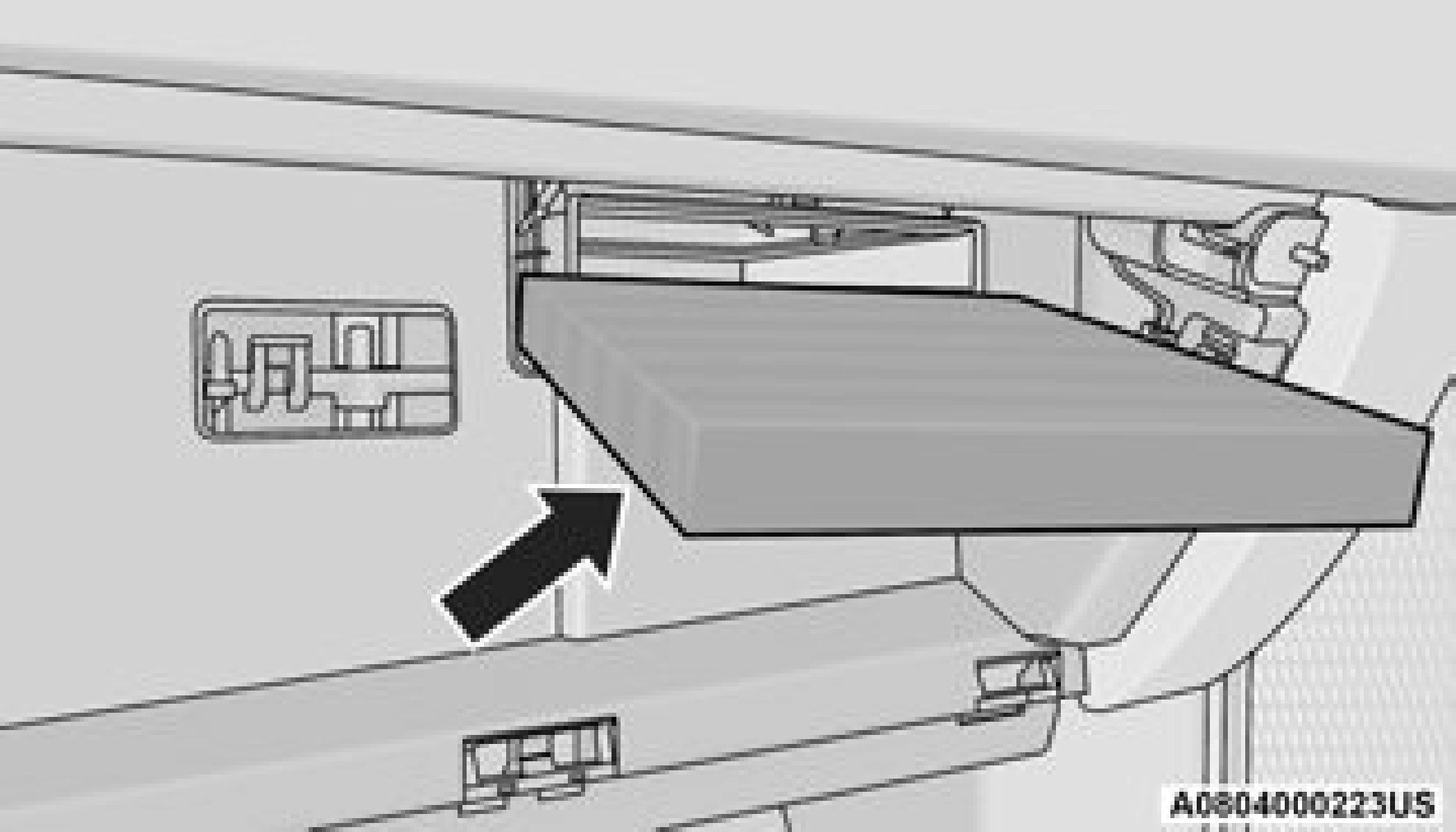
The cabin air filter is located in the fresh air inlet behind the glove compartment. Perform the following procedure to replace the filter:
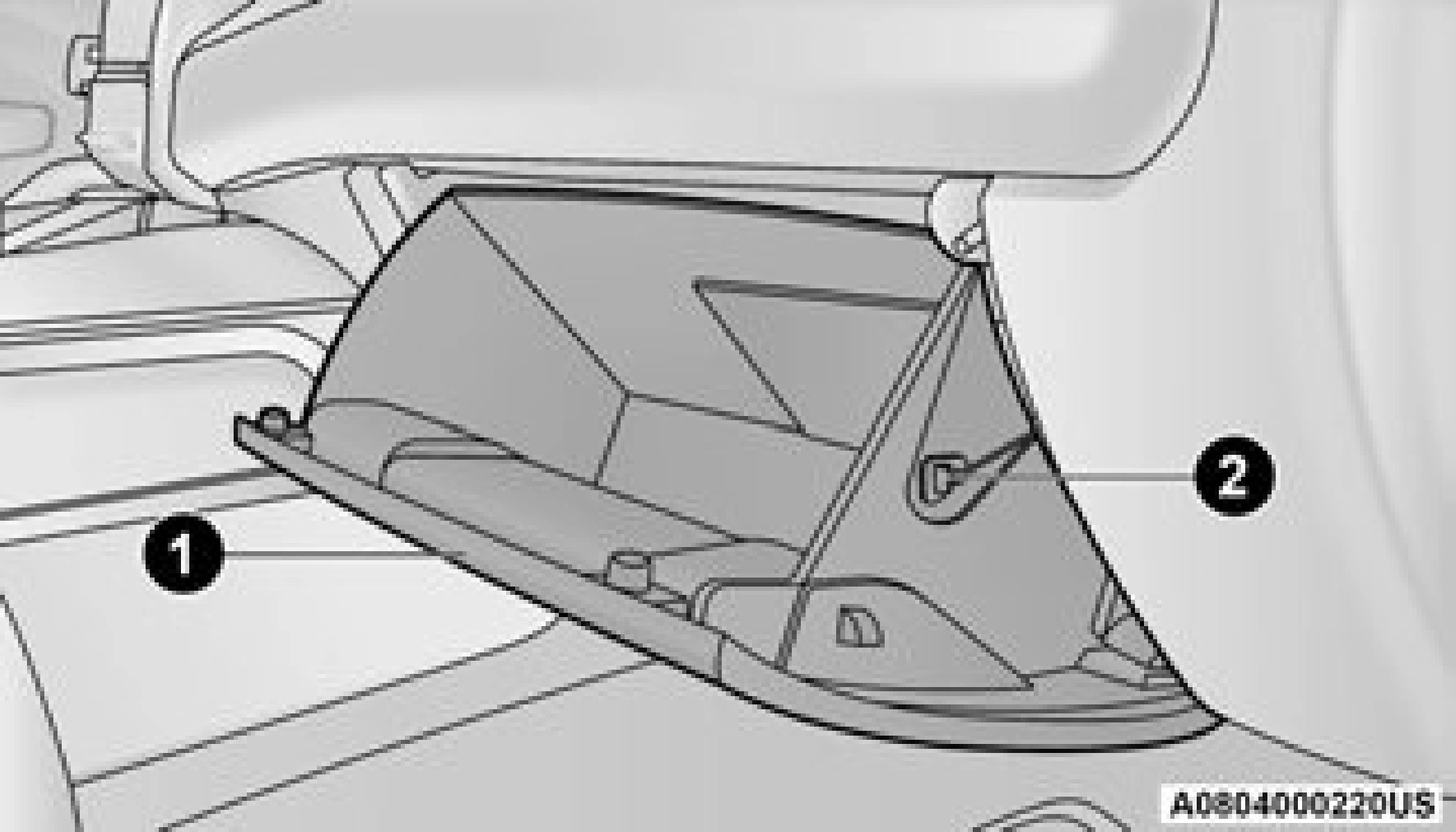

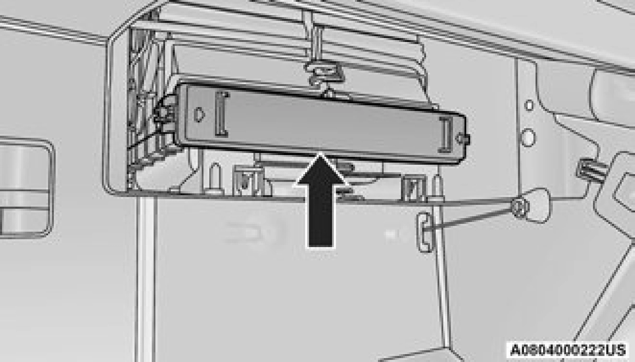
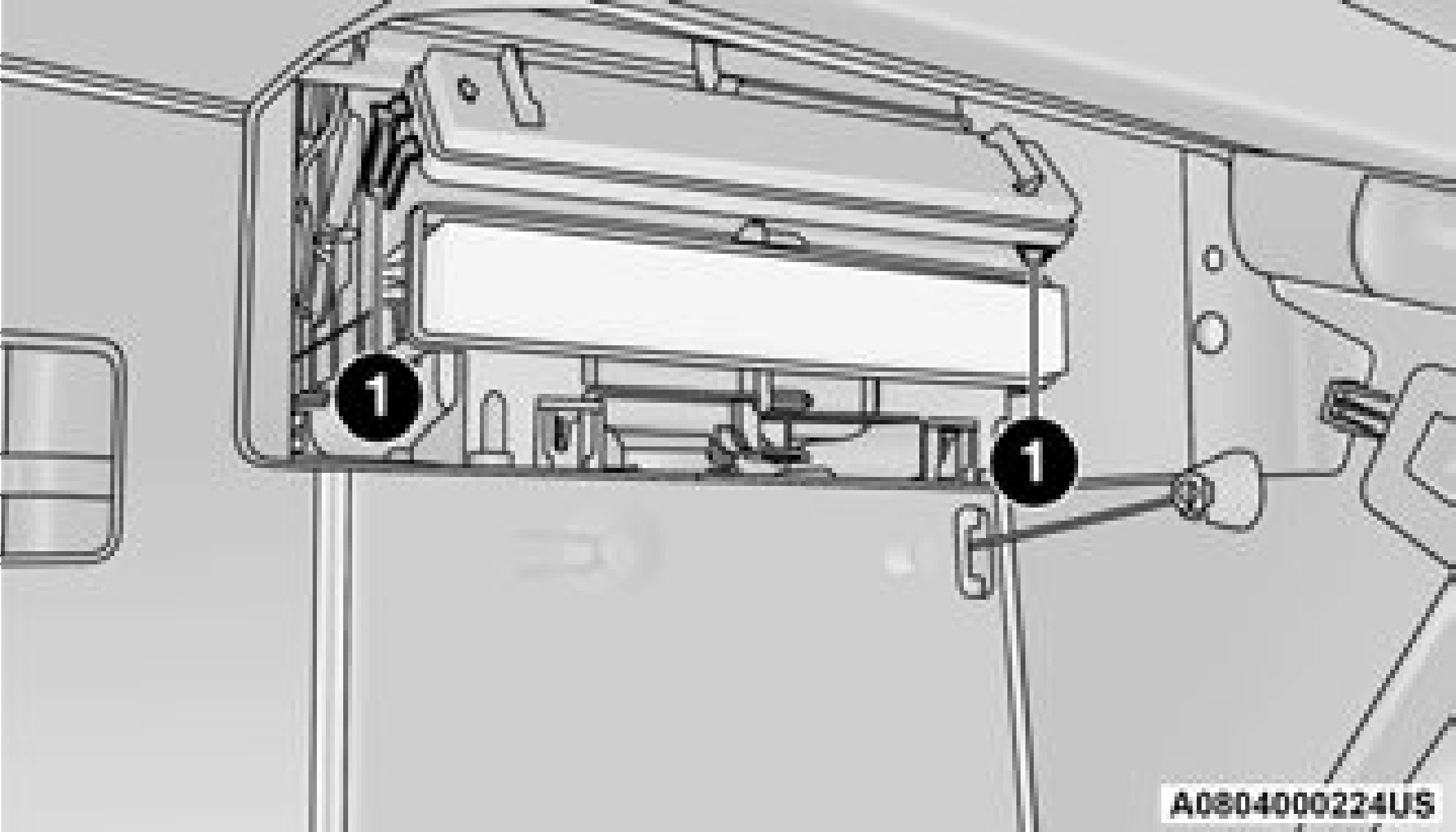
Filter Cover Removal
1 — Finger Tabs
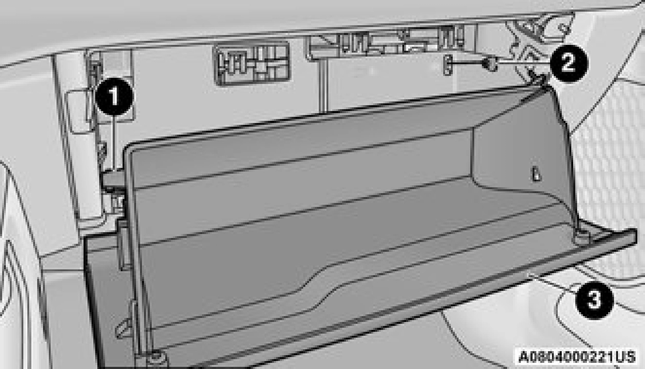
Ensure the glove compartment door hinges and glove compartment travel stops are fully engaged.
ACCESSORY DRIVE BELT INSPECTION
8
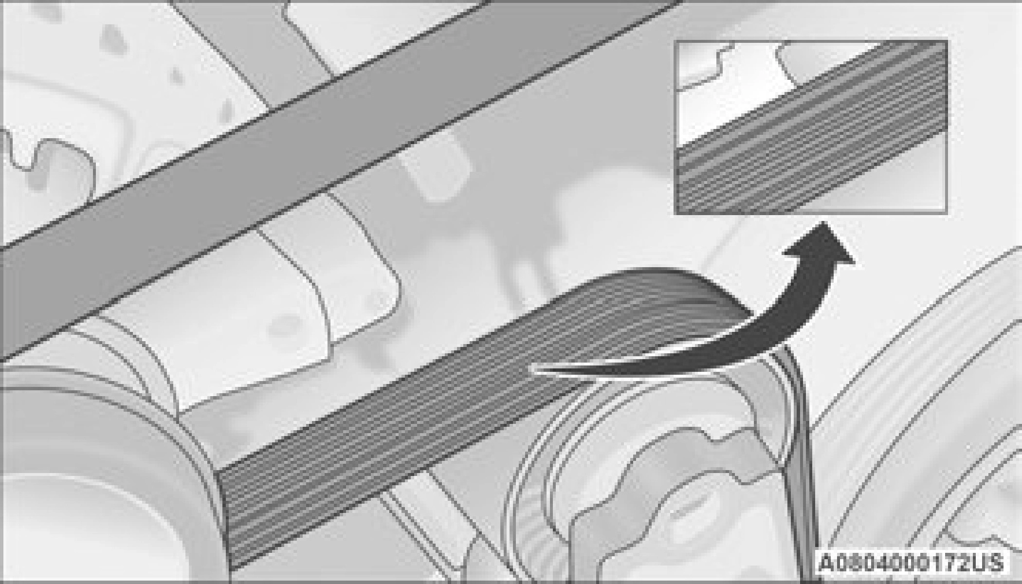
When inspecting accessory drive belts, small
cracks that run across the ribbed surface of the belt from rib to rib, are considered normal. This is not a reason to replace the belt. However, cracks running along a rib (not across) are not normal. Any belt with cracks running along a rib must be replaced. Also have the belt replaced if it has excessive wear, frayed cords or severe glazing.
Conditions that would require replacement:
Identify and correct problem before new belt is installed.
If your vehicle is equipped with a Stop/Start, belt must be replaced with an OEM grade Mopar belt.
Some conditions can be caused by a faulty component such as a belt pulley. Belt pulleys should be carefully inspected for damage and proper alignment.
Belt replacement on some models requires the use of special tools, we recommend having your vehicle serviced at an authorized dealer.
BODY LUBRICATION
Locks and all body pivot points, including such items as seat tracks, door hinge pivot points and rollers, liftgate, tailgate, decklid, sliding doors and hood hinges, should be lubricated periodically. Use a lithium-based grease, such as Mopar Spray White Lube to assure quiet, easy operation and to protect against rust and wear. Prior to the application of any lubricant, the parts concerned should be wiped clean to remove dust and grit; after lubricating excess oil and grease should be removed. Particular
attention should also be given to hood latching components to ensure proper function. When performing other underhood services, the hood latch release mechanism, and safety catch should be cleaned and lubricated.
The external lock cylinders should be lubricated twice a year, preferably in the Autumn and Spring. Apply a small amount of a high quality lubricant, such as Mopar Lock Cylinder Lubricant directly into the lock cylinder.
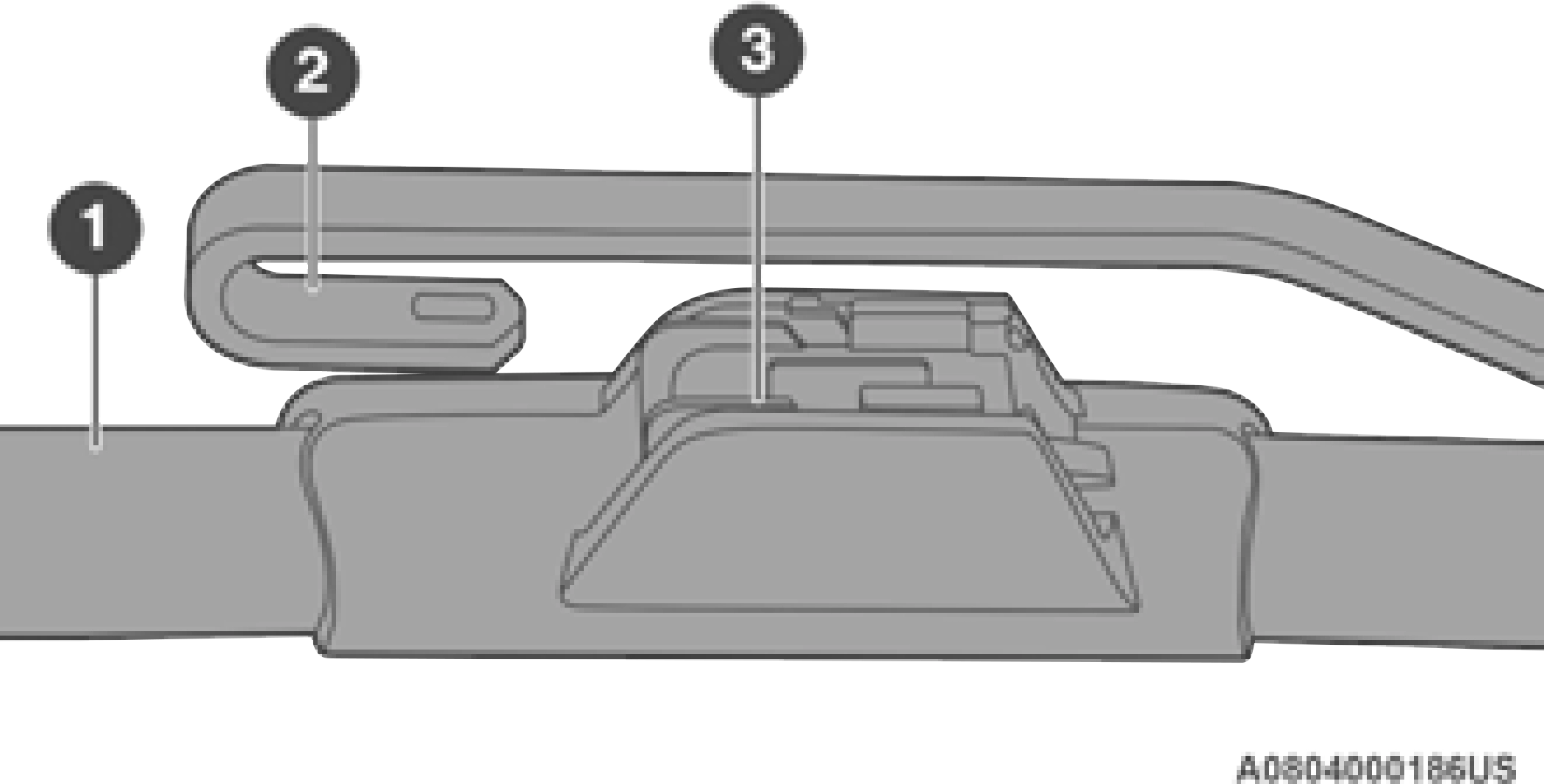
WINDSHIELD WIPER BLADES
Clean the rubber edges of the wiper blades and the windshield periodically with a sponge or soft cloth and a mild nonabrasive cleaner. This will remove accumulations of salt or road film.
Operation of the wipers on dry glass for long periods may cause deterioration of the wiper blades. Always use washer fluid when using the wipers to remove salt or dirt from a dry windshield.
Avoid using the wiper blades to remove frost or ice from the windshield. Keep the blade rubber out of contact with petroleum products such as engine oil, gasoline, etc.
Life expectancy of wiper blades varies depending on geographical area and frequency of use. If chattering, marks, water lines or wet spots are present, clean the wiper blades or replace as necessary.
The wiper blades and wiper arms should be inspected periodically, not just when wiper performance problems are experienced. This inspection should include the following points:
If a wiper blade or wiper arm is damaged, replace the affected wiper arm or blade with a new unit. Do not attempt to repair a wiper arm or blade that is damaged.
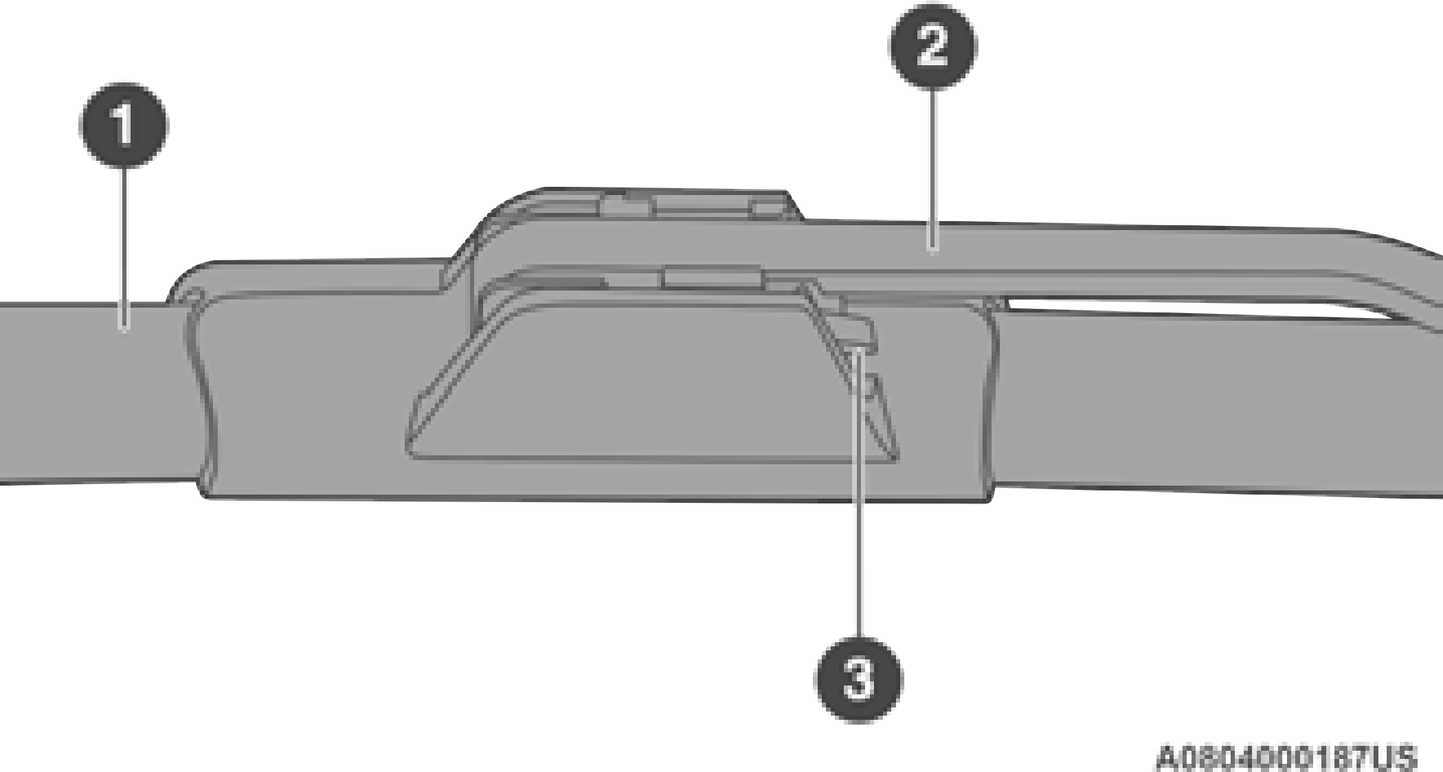
1 — Wiper Blade 2 — Wiper Arm 3 — Release Tab
EXHAUST SYSTEM
The best protection against carbon monoxide entry into the vehicle body is a properly maintained engine exhaust system.
If you notice a change in the sound of the exhaust system; or if the exhaust fumes can be detected inside the vehicle; or when the underside or rear of the vehicle is damaged; have an authorized technician inspect the complete exhaust system and adjacent body areas for broken, damaged, deteriorated, or mispositioned parts. Open seams or loose connections could permit exhaust fumes to seep into the passenger compartment. In addition, have the exhaust system inspected
each time the vehicle is raised for lubrication or oil change. Replace as required.
(Continued)
Under normal operating conditions, the catalytic converter will not require maintenance. However, it is important to keep the engine properly tuned to assure proper catalyst operation and prevent possible catalyst damage.
Intentional tampering with emissions control systems can result in civil penalties being assessed against you.
In unusual situations involving grossly malfunctioning engine operation, a scorching odor may suggest severe and abnormal catalyst
overheating. If this occurs, stop the vehicle, turn off the engine and allow it to cool. Service, including a tune-up to manufacturer's specifications, should be obtained immediately.
To minimize the possibility of catalytic converter damage:
COOLING SYSTEM Engine Coolant Checks
Check the engine coolant (antifreeze) protection every 12 months (before the onset of freezing weather, where applicable). If the engine coolant is dirty or rusty in appearance, the system should be drained, flushed and refilled with fresh coolant. Check the front of the A/C condenser (if equipped) or radiator for any accumulation of bugs, leaves, etc. If dirty, clean by gently spraying water from a garden hose vertically down the face of the A/C condenser (if equipped) or the back of the radiator core.
Check the engine cooling system hoses for brittle rubber, cracking, tears, cuts and tightness of the connection at the coolant recovery bottle and radiator. Inspect the entire system for leaks.
DO NOT REMOVE THE COOLANT PRESSURE CAP WHEN THE COOLING SYSTEM IS HOT.
Some vehicles require special tools to add coolant properly. Failure to fill these systems properly could lead to severe internal engine damage. If any coolant is needed to be added to the system please contact an authorized dealer.
If the engine coolant (antifreeze) is dirty or contains visible sediment, have an authorized dealer clean and flush with OAT coolant (conforming to MS.90032).
For the proper maintenance intervals
page 395.
For further information page 475. NOTE:
non-OAT engine coolant is introduced into the cooling system in an emergency, the cooling system will need to be drained, flushed, and refilled with fresh OAT coolant (conforming to MS.90032), by an authorized dealer as soon as possible.
Your vehicle has been built with an improved engine coolant (OAT coolant conforming to MS.90032) that allows extended maintenance intervals. This engine coolant (antifreeze) can
be used up to 10 years or 150,000 miles (240,000 km) before replacement. To prevent reducing this extended maintenance period, it is important that you use the same engine coolant (OAT coolant conforming to MS.90032) throughout the life of your vehicle.
Please review these recommendations for using Organic Additive Technology (OAT) engine coolant that meets the requirements of FCA Material Standard MS.90032. When adding engine coolant:
The cap must be fully tightened to prevent loss of engine coolant (antifreeze), and to ensure that engine coolant will return to the radiator from the coolant expansion bottle/recovery tank (if equipped).
The cap should be inspected and cleaned if there is any accumulation of foreign material on the sealing surfaces.
Used ethylene glycol-based coolant (antifreeze) is a regulated substance requiring proper disposal. Check with your local authorities to determine the disposal rules for your community. To prevent ingestion by animals or children, do not store ethylene glycol-based coolant in open containers or allow it to remain in puddles on the ground, clean up any ground spills immediately. If ingested, seek emergency assistance immediately.
Checking Coolant Level — 3.6L Engine The level of the coolant in the pressurized coolant bottle should be between the “MIN” and
“MAX” range on the bottle when the engine is
cold.
The radiator normally remains completely full, so there is no need to remove the cap unless checking for coolant freeze point or replacing engine coolant (antifreeze). Advise your service attendant of this. As long as the engine operating temperature is satisfactory, the coolant bottle need only be checked once a month. When additional engine coolant is needed to maintain the proper level, it should be added to the coolant bottle. Do not overfill.
With the engine off and cold, the level of the
engine coolant should be between the ADD and 8
SAFE range on the dipstick.
To check the coolant level:
The radiator normally remains completely full, so there is no need to remove the radiator cap unless checking for engine coolant (antifreeze) freeze point or replacing engine coolant. Advise your service attendant of this. As long as the engine operating temperature is satisfactory, the coolant bottle need only be checked once a month.
When additional engine coolant is needed to maintain the proper level, it should be added to the coolant bottle. Do not overfill.
When the vehicle is stopped after a few miles/ kilometers of operation, you may observe vapor coming from the front of the engine compart- ment. This is normally a result of moisture from rain, snow, or high humidity accumulating on the radiator and being vaporized when the ther- mostat opens, allowing hot engine coolant (anti- freeze) to enter the radiator.
If an examination of your engine compartment shows no evidence of radiator or hose leaks, the vehicle may be safely driven. The vapor will soon dissipate.
CHARGE AIR COOLER — INTER-COOLER (DIESEL ENGINE)
The charge air cooler is positioned in front of the radiator and the air conditioner condenser. Air enters the engine through the air cleaner and passes through the turbocharger, where it is pressurized. This pressurized air rapidly reaches high temperature. The air is then directed through a hose to the charge air cooler
and through another hose to the intake manifold of the engine. This cooling process enables more efficient burning of fuel resulting in fewer emissions.
To guarantee optimum performance of the system, keep the surfaces of the charge air cooler, condenser and radiator clean and free of debris. Periodically check the hoses leading to and from the charge air cooler for cracks or loose clamps resulting in loss of pressure and reduced engine performance.
BRAKE SYSTEM
In order to ensure brake system performance, all brake system components should be inspected periodically page 395.
Fluid Level Check — Brake Master Cylinder The fluid level of the brake master cylinder should be checked whenever the vehicle is
serviced, or immediately if the brake system
warning light is on. If necessary, add fluid to bring level within the designated marks on the side of the reservoir of the brake master cylinder. Be sure to clean the top of the master cylinder area before removing cap. With disc brakes, fluid level can be expected to fall as the brake pads wear. Brake fluid level should be checked when pads are replaced. If the brake fluid is abnormally low, check the system for leaks page 478.
(Continued)
AUTOMATIC TRANSMISSION
FCA strongly recommends against using any special additives in the transmission. Automatic Transmission Fluid (ATF) is an engineered product and its performance may be impaired by supplemental additives. Therefore, do not add any fluid additives to the transmission.
Avoid using transmission sealers as they may adversely affect seals.
The fluid level is preset at the factory and does not require adjustment under normal operating conditions. Routine fluid level checks are not required, therefore the transmission has no dipstick. An authorized dealer can check your transmission fluid level using special service tools.
If you notice fluid leakage or transmission malfunction, visit an authorized dealer immediately to have the transmission fluid level checked. Operating the vehicle with an improper fluid level can cause severe transmission damage.
Under normal operating conditions, the fluid installed at the factory will provide satisfactory lubrication for the life of the vehicle.
Routine fluid and filter changes are not required. However, change the fluid and filter if the fluid becomes contaminated (with water, etc.), or if the transmission is disassembled for any reason.
It is important to use the proper transmission fluid to ensure optimum transmission
performance and life. Use only the recommended transmission fluid page 478. It is important to maintain the transmission fluid at the correct level using the recommended fluid. No chemical flushes should be used in any transmission; only the approved lubricant should be used.
REAR AXLE AND 4X4 FRONT DRIVING AXLE FLUID LEVEL
For normal service, periodic fluid level checks are not required. When the vehicle is serviced for other reasons the exterior surfaces of the axle assembly should be inspected. If gear oil leakage is suspected inspect the fluid level
page 478. This inspection should be made
with the vehicle in a level position.
The fluid level should be even with the bottom of the fill hole (within 1/4 in (6.4 mm) of edge of hole) for the front axle and rear axle.
For the proper maintenance intervals
page 395.
For further information page 478.
The presence of water in the gear lubricant will result in corrosion and possible failure of differ- ential components. Operation of the vehicle in water, as may be encountered in some
off-highway types of service, will require draining and refilling the axle to avoid damage.
Rear axles equipped with a Limited Slip Differential require that 5 oz. (148 ml) Mopar Limited Slip Additive be added to the gear lubricant page 478. The Mopar Limited Slip Additive should be added to the gear lubricant whenever a fluid change is made to an axle equipped with a Limited Slip Differential.
When refilling a limited slip differential axle which requires a friction modification additive, the additive should be added before the gear lubricant to ensure proper additive fill.
TRANSFER CASE
This fluid level can be checked by removing the filler plug. The fluid level should be to the bottom edge of the filler plug hole (or within 1/8 inch of the bottom) with the vehicle in a level position.
For the proper maintenance intervals
page 395.
Use only the recommended fluid page 478.
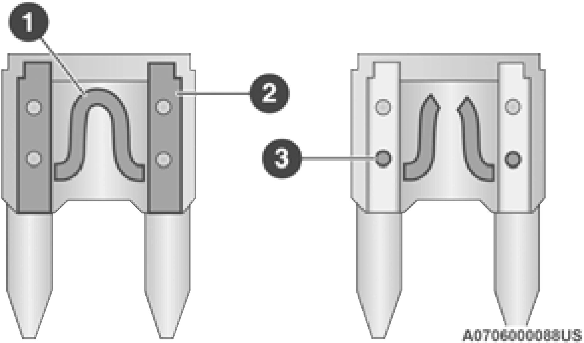
FUSES
The fuses protect electrical systems against excessive current.
When a device does not work, you must check the fuse element inside the blade fuse for a break/melt.
Also, please be aware that when using power outlets for extended periods of time with the engine off may result in vehicle battery discharge.
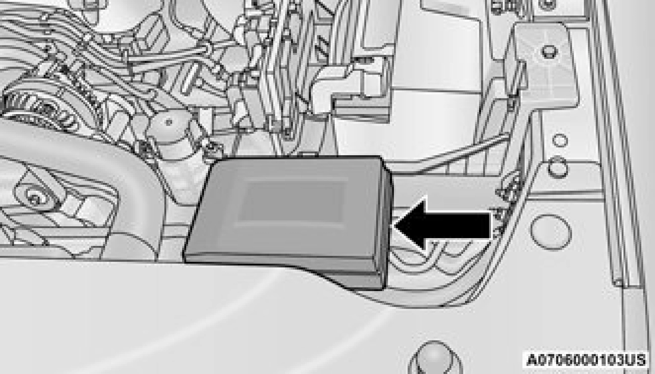
The Power Distribution Center is located in the engine compartment near the battery. This center contains cartridge fuses, micro fuses, relays, and circuit breakers. A description of each fuse and component may be stamped on the inside cover, otherwise the cavity number of each fuse is stamped on the inside cover that corresponds to the following chart.
|
Cavity |
Cartridge Fuse |
Micro Fuse |
Description |
|
F01 |
– |
25 Amp Clear |
Fuel Pump Motor |
|
F03 |
– |
5 Amp Tan |
MGU |
|
F04 |
– |
– |
Spare |
|
F05 |
– |
– |
Spare |
8
|
Cavity |
Cartridge Fuse |
Micro Fuse |
Description |
|
F26 |
50 Amp Red |
– |
ESP Module |
|
F27 |
30 Amp Pink |
– |
Front Wiper |
|
F28 |
– |
10 Amp Red |
PCM / ECM |
|
F29 |
40 Amp Green |
– |
ESP Module |
|
F30 |
– |
– |
Spare |
|
F31 |
– |
– |
Spare |
|
F32 |
20 Amp Blue |
– |
ECM / PCM |
|
F33 |
30 Amp Pink |
– |
Brake Vacuum Pump |
|
F34 |
– |
– |
Spare |
|
F35 |
– |
10 Amp Red |
PCM / ECM / Power Pack Unit (PPU) Motor Generator Unit (MGU) Wake Up / EPS / Active Tuned Mass Module (ATMM) / ESP |
|
F36 |
– |
– |
Spare |
|
F37 |
– |
5 Amp Tan |
R / S Output to iPDC |
|
F38 |
– |
10 Amp Red |
DTCM / Active CL TEMP VLV |
|
F39 |
– |
15 Amp Red |
MOD ATMM |
|
F40 |
40 Amp Green |
– |
Starter |
|
F41 |
– |
10 Amp Red |
IRCAM Heaters |
|
F42 |
20 Amp Blue |
– |
AUX SWITCH #5 — If Equipped |
|
F43 |
– |
20 Amp Yellow |
MGU Coolant Pump |
|
F44 |
– |
10 Amp Red |
Trailer Camera |
|
F45 |
– |
10 Amp Red |
ADCM — If Equipped |
8
The Power Distribution Center is located under the drivers side instrument panel. This center contains cartridge fuses, micro fuses, relays, and circuit breakers. A description of each fuse and component may be stamped on the inside cover, otherwise the cavity number of each fuse is stamped on the inside cover that corresponds to the following chart.
|
Cavity |
Cartridge Fuse |
Micro Fuse |
Description |
|
F01 |
30 Amp Pink |
– |
Trailer Tow Receptacle |
|
F03 |
– |
20 Amp Yellow |
Module Seat Heater Front (Pass) |
|
F04 |
– |
– |
Spare |
|
F05 |
– |
20 Amp Yellow |
Module PPU Cooling Fan |
|
F06 |
– |
– |
Spare |
|
F07 |
40 Amp Green |
– |
Mod CBC 3 PWR Locks |
|
F08 |
– |
– |
Spare |
8
|
Cavity |
Cartridge Fuse |
Micro Fuse |
Description |
|
F29 |
– |
20 Amp Yellow |
Mod CRSM (Heat Rear LT) |
|
F30 |
30 Amp Pink |
– |
Mod DTCM / Mod Tailgate |
|
F31 |
30 Amp Pink |
– |
Mod CBC 1 Interior Light |
|
F32 |
– |
20 Amp Yellow |
RT Spot Lamp — If Equipped |
|
F33 |
– |
10 Amp Red |
Assy Overhead Console / Switch 911 / Switch Assist / Heads Up Display (HUD) |
|
F34 |
– |
15 Amp Blue |
Frt & RR Ventilated Seat Motor |
|
F35 |
– |
10 Amp Red |
Mod Inverter / Mtr Sunshade Sunroof / Mtr Dual Sunroof / USB Charge Only |
|
F36 |
40 Amp Green |
– |
Mod CBC 2 Exterior Light 1 |
|
F37 |
– |
– |
Spare |
|
F38 |
– |
– |
Spare |
|
F39 |
– |
– |
Spare |
|
F40 |
20 Amp Blue |
– |
Dome Pursuit Vehicle — If Equipped |
|
F41 A&B |
– |
15 Amp Blue |
Lumbar Support & Pass SW / Mod ICS Sw Bank / HVAC Ctrl / Sw Bank Upper / Mod Ctrl Steering |
|
F42 A&B |
– |
10 Amp Red |
Mod Transfer Case Switch Module (TCSM) / SBW / Electric Park Brake SW / Overhead Console (OHC) SW / E-Call / Bank 3 SW / Seat LT & RT Vent / Mod Trailer A&B Tire Pressure / Mod Gateway Trailer |
|
F43 A&B |
– |
10 Amp Red |
Port Diagnostics / Mod CD / Front & Rear USB |
|
F44 |
– |
20 Amp Yellow |
Radio / DCSD / Telematics Box Mod / Fleet Telematics Module (FTM) |
8
|
Cavity |
Cartridge Fuse |
Micro Fuse |
Description |
|
F63 |
– |
– |
Spare |
|
F64 |
– |
– |
Spare |
|
F65 |
– |
10 Amp Red |
Mod ORC |
|
F66 |
– |
10 Amp Red |
Run Accessory Feed — If Equipped |
BULB REPLACEMENT
See an authorized dealer for LED bulb replacement.
All of the inside bulbs are brass or glass-wedge base. Aluminum base bulbs are not approved.
|
Interior Bulbs |
|
|
Bulb Name |
Bulb Number |
|
Overhead Console Lamps |
TS 212–9 |
|
Dome Lamp |
7679 |
|
NOTE: For lighted switches, see an authorized dealer for replacement instructions. |
8
|
Exterior Bulbs |
|
|
Bulb Name |
Bulb Number |
|
Front Side Marker (Halogen Reflector Headlamp) |
W5W |
|
Front Side Marker (LED Headlamps) |
LED (Serviced at an authorized dealer) |
|
Front Fog Lamps (Halogen Reflector Headlamp) |
H11LL |
|
Front Fog Lamps (LED Headlamps) |
LED (Serviced at an authorized dealer) |
|
Side Indicators (Front And Side View Mirror) |
LED (Serviced at an authorized dealer) |
|
Base Rear Tail/Turn and Stop Lamp |
7440LL/W21WLL |
|
Premium Rear Tail/Turn/Backup and Stop Lamp |
LED (Serviced at an authorized dealer) |
|
Base Backup Lamp |
7440/W21W |
|
Center High Mounted Stop Lamp (CHMSL) |
921 |
|
Cargo Lamp |
921 |
|
Rear License Plate Lamp |
LED (Serviced at an authorized dealer) |
|
Base Turn Lamp |
7440NA / WY21W |
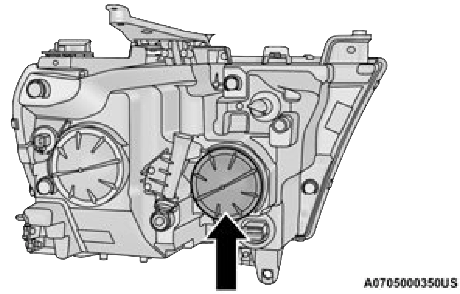
Base Quad: Low Beam Headlamp, High Beam Headlamp, Front Park And Turn — If Equipped
Low Beam
See below steps to replace:
It may be necessary to remove/reposition Air Cleaner Assembly to access passenger side headlamp/side marker light bulbs.
 High Beam Headlight Cover
can be found on the back side of the headlamps.
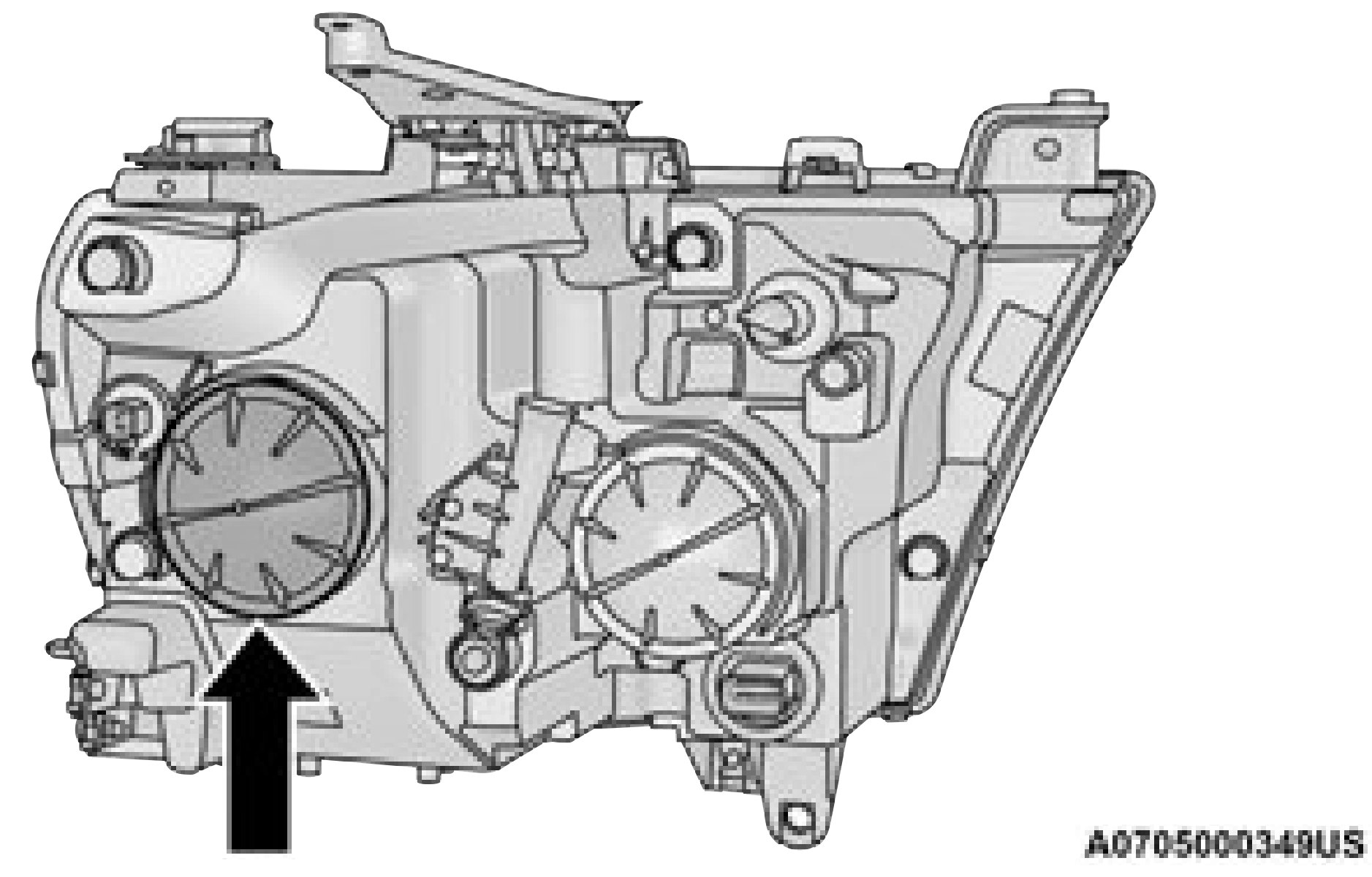
See below steps to replace:
It may be necessary to remove/reposition Air Cleaner Assembly to access passenger side headlamp/side marker light bulbs.
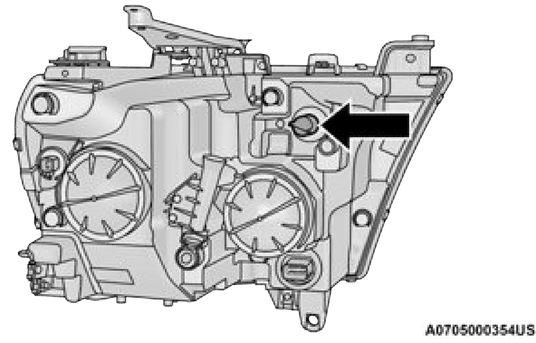
See below steps to replace:
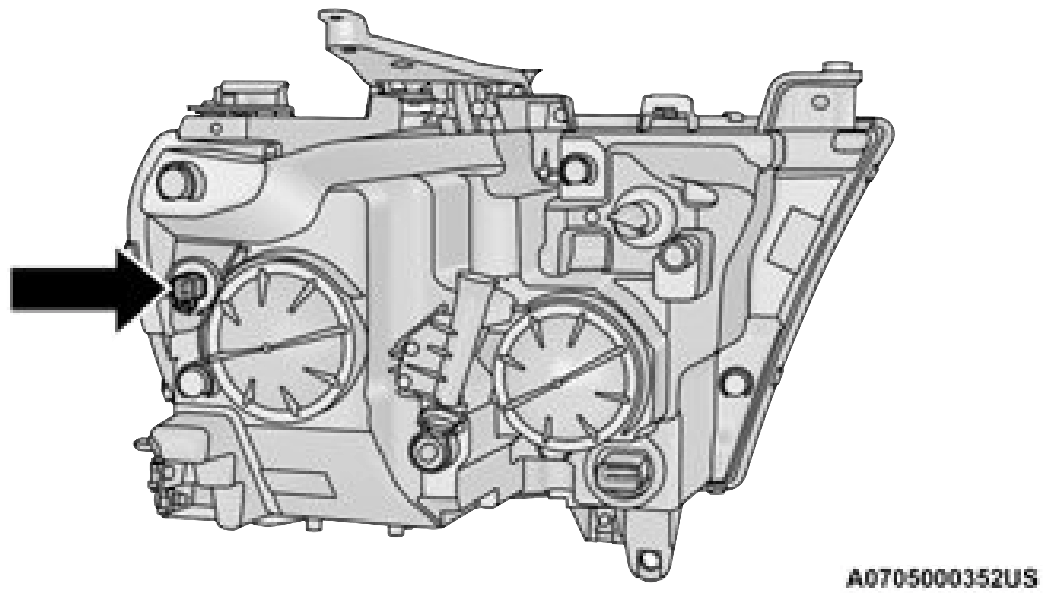
See below steps to replace:
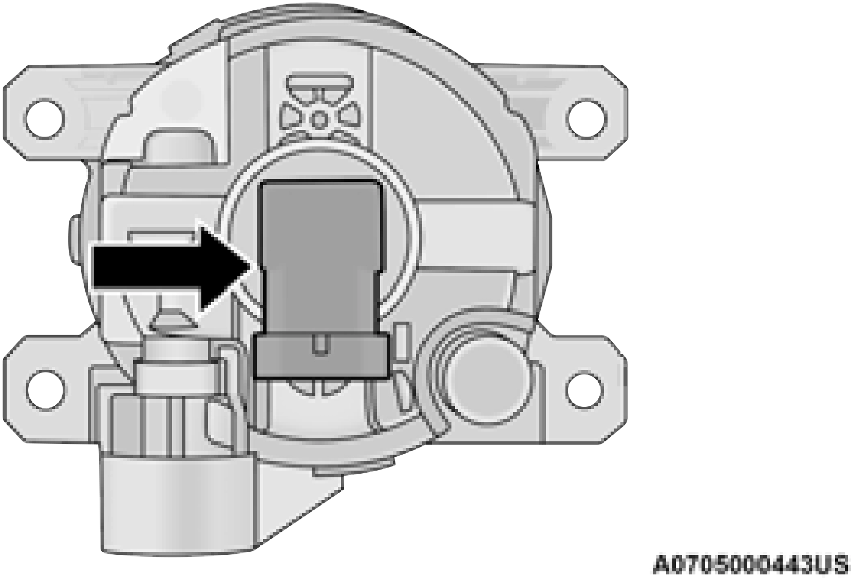
Fog Lamps — If Equipped
Please see an authorized dealer for service on LED and Halogen front fog lamps.
See below steps to replace:
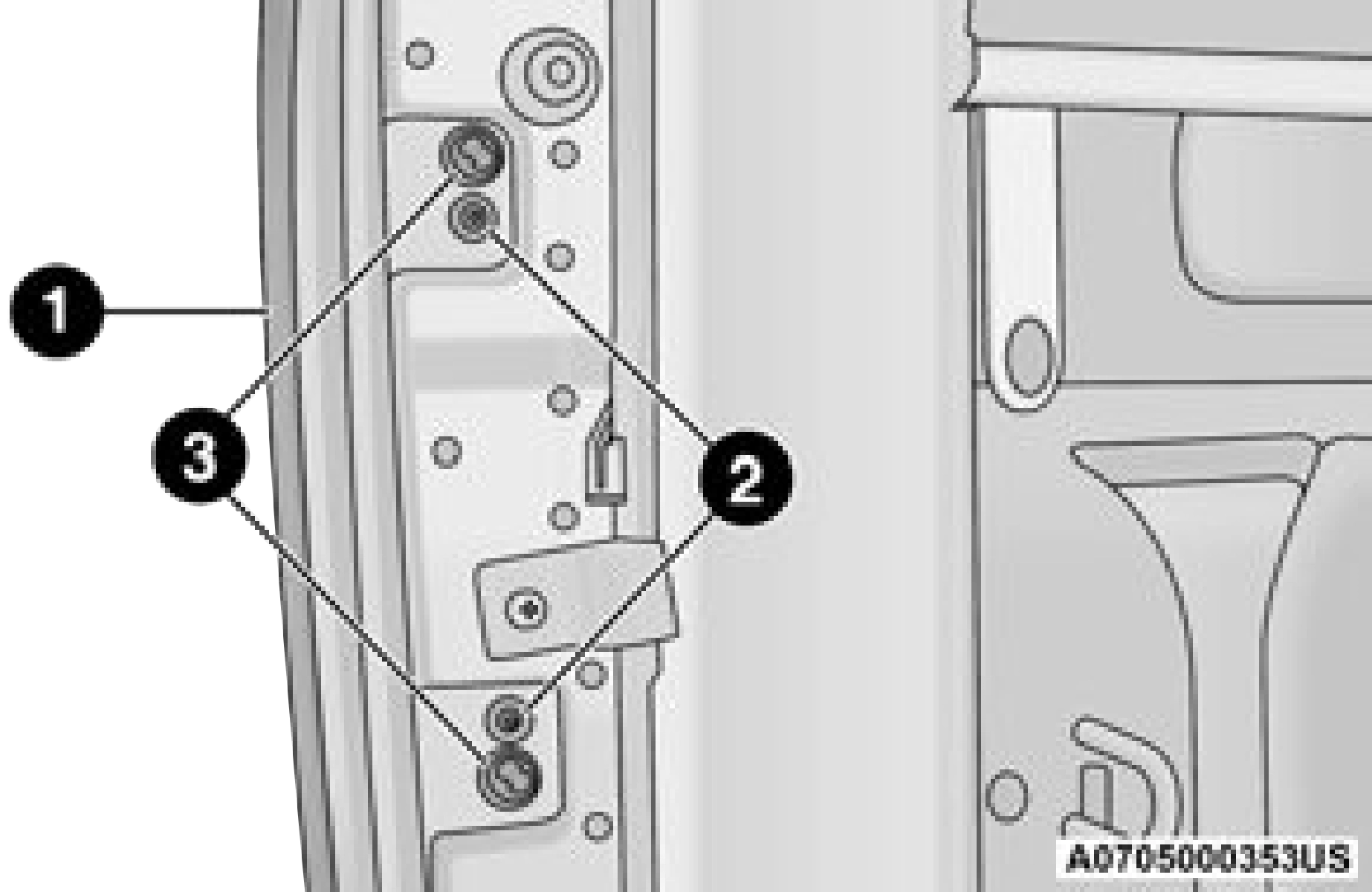
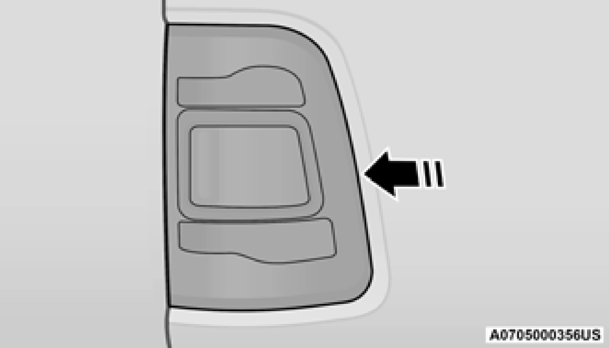
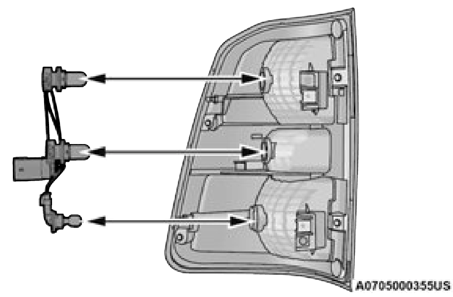
Rear Tail/Stop, Turn Signal And Backup Lamps See below steps to replace:
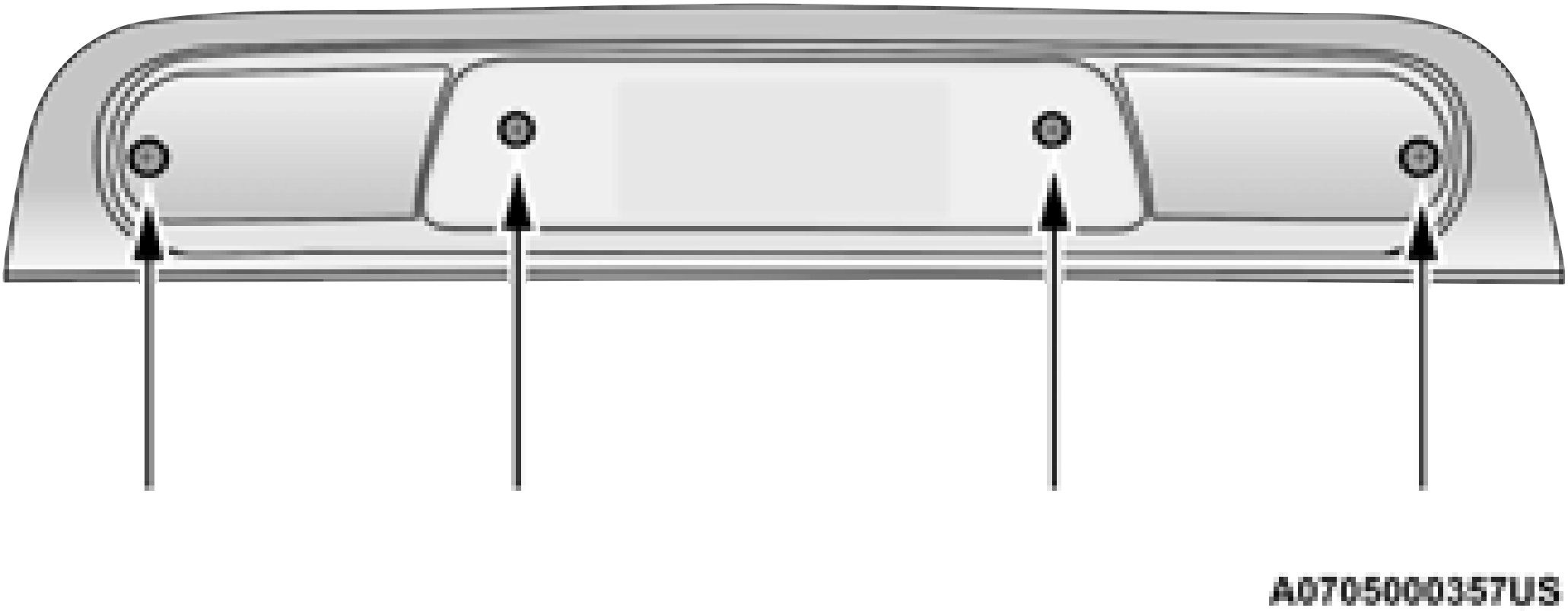
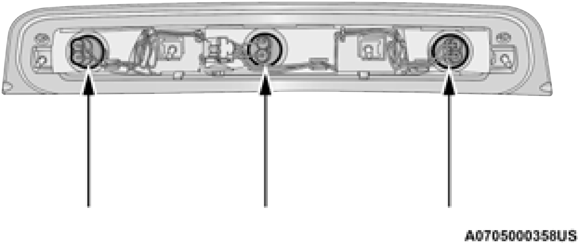
Center High Mounted Stop Lamp (CHMSL) With Cargo Lamp
See below steps to replace:
TIRE SAFETY INFORMATION
Tire Markings
8
design standards and it begins with the tire diameter molded into the sidewall. Example: 31x10.5 R15 LT.
Download Manual