AUXILIARY DRIVING SYSTEMS
BLIND SPOT MONITORING (BSM) — IF EQUIPPED
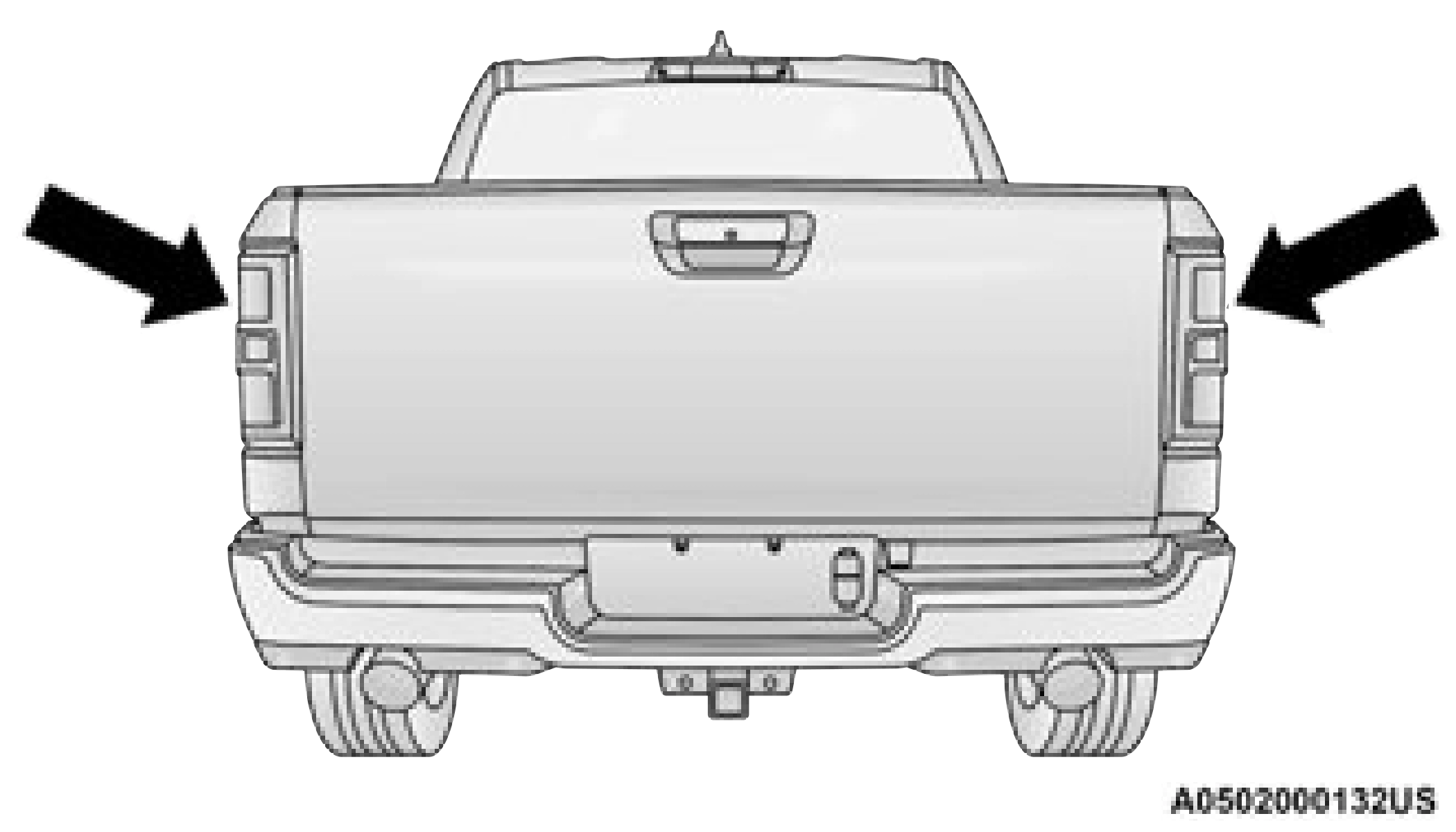
BSM uses two radar sensors, located inside the taillights, to detect highway licensable vehicles (automobiles, trucks, motorcycles, etc.) that enter the blind spot zones from the rear/front/ side of the vehicle.
When the vehicle is started, the BSM Warning Light will momentarily illuminate in both outside rearview mirrors to let the driver know that the system is operational. The BSM system sensors operate when the vehicle is in any forward gear or REVERSE and enters standby mode when the vehicle is in PARK.
The BSM detection zone covers approximately one lane width on both sides of the vehicle 12 ft (3.8 m). The zone length starts at the outside rear view mirror and extends approximately
10 ft (3 m) beyond the rear fascia/bumper of the vehicle. The BSM system monitors the detection zones on both sides of the vehicle when the vehicle speed reaches approximately 6 mph (10 km/h) or higher and will alert the driver of vehicles in these areas.
The vehicle’s taillights, where the radar sensors are located, must remain free of snow, ice, and dirt/road contamination so that the BSM system can function properly. Do not block the taillights with foreign objects (bumper stickers, bicycle racks, etc.).
If the system detects degraded performance due to contamination or foreign objects, a message will warn you of a blocked sensor and the warning indicators in side view mirrors will be on. The warning indicators will remain illuminated until blockage clearing conditions are met. First clear the taillights around the sensors of the blockage. After removing the blockage, the following procedure can be used to reset the system:
Cycle the ignition from ON to OFF and then back ON.
If the blockage message is still present after cycling the ignition and driving in traffic, check again for a blockage.
The system may also detect a blockage if the vehicle is operated in areas with extremely low radar returns such as a desert or parallel to a large elevation drop.
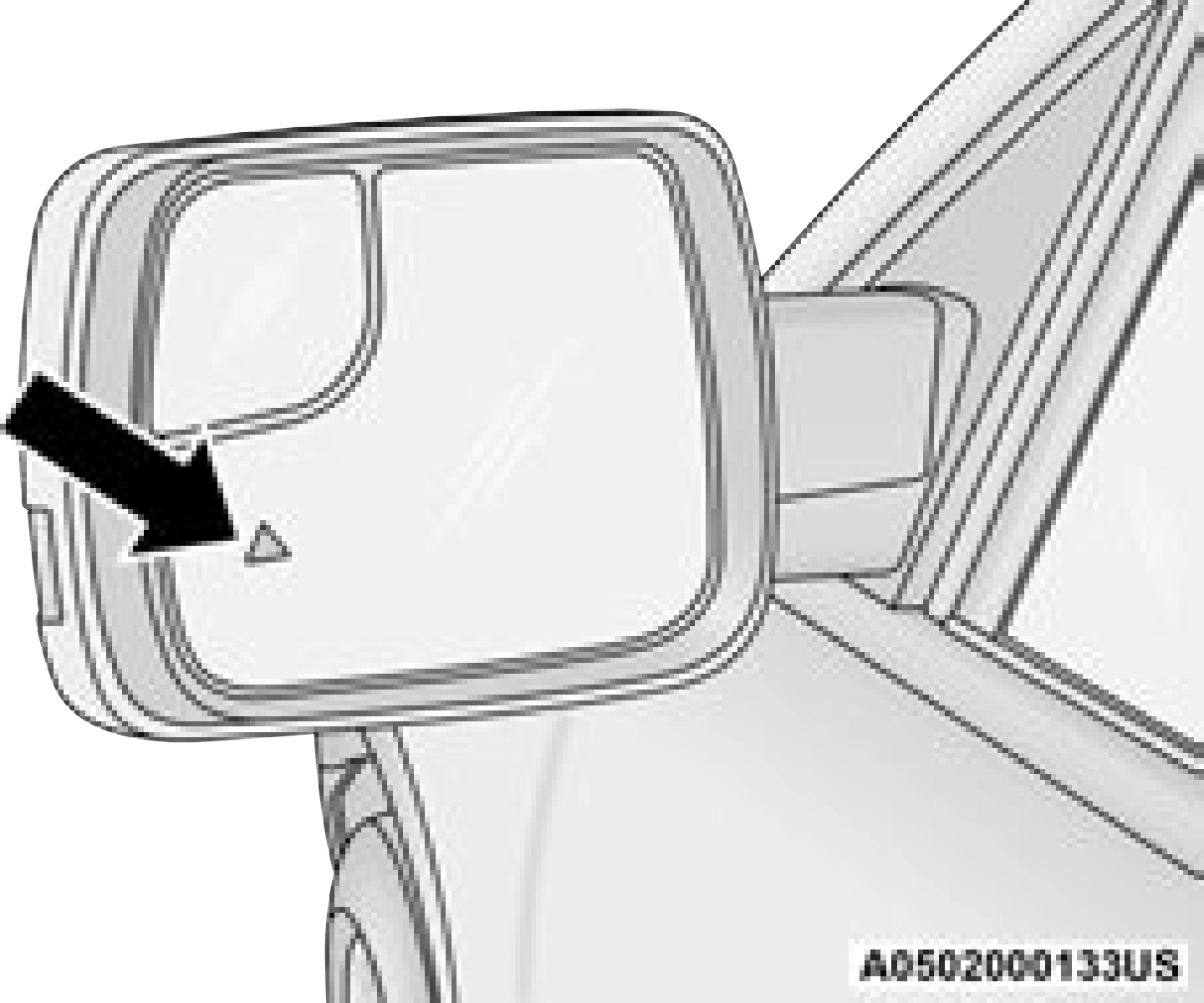 The BSM system notifies the driver of objects in the detection zones by illuminating the BSM warning light located in the outside mirrors, in addition to sounding an audible (chime) alert and reducing the radio volume page 322.
6
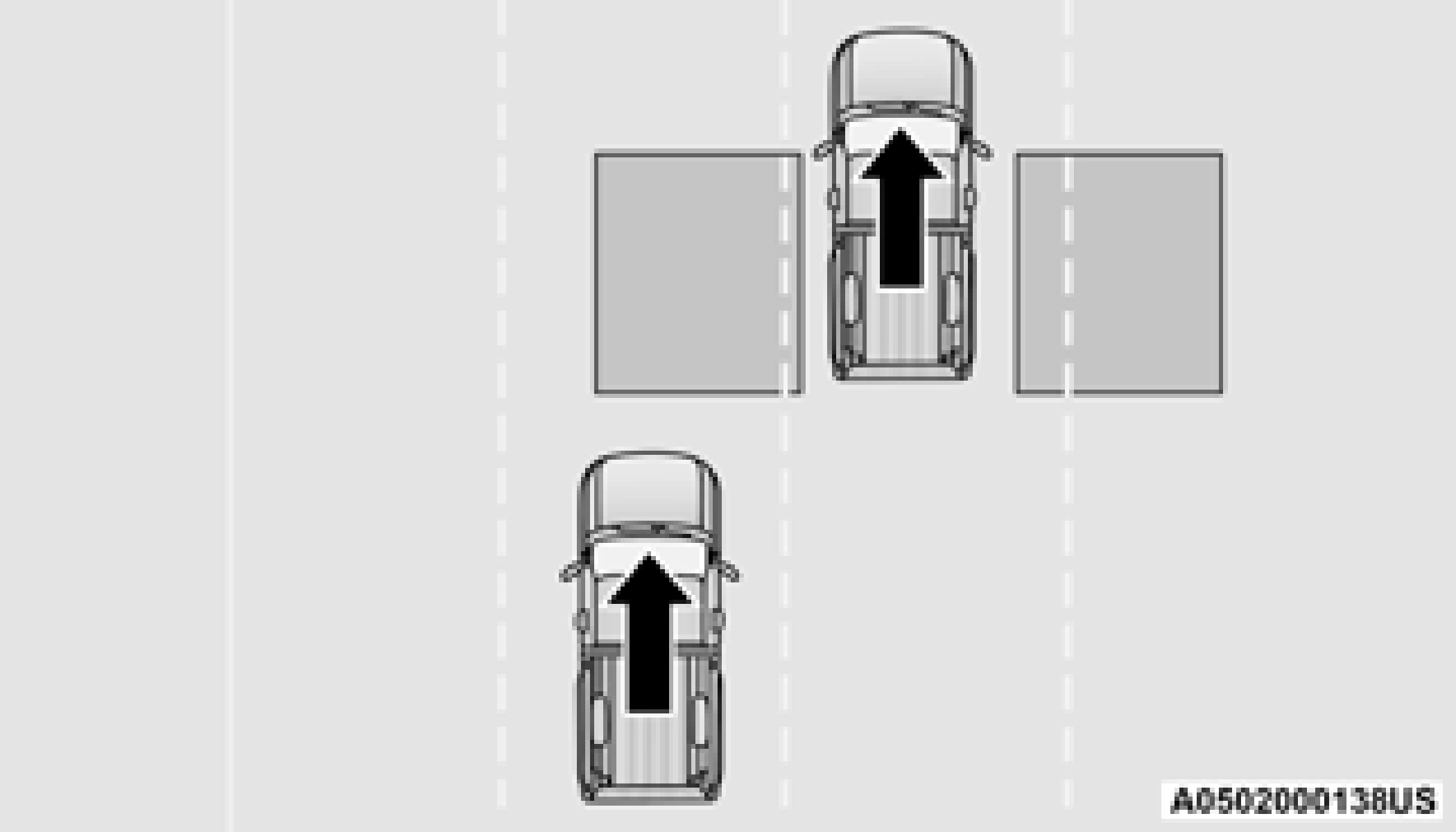
The BSM system monitors the detection zone from three different entry points (side, rear, front) while driving to see if an alert is necessary. The BSM system will issue an alert during these types of zone entries.
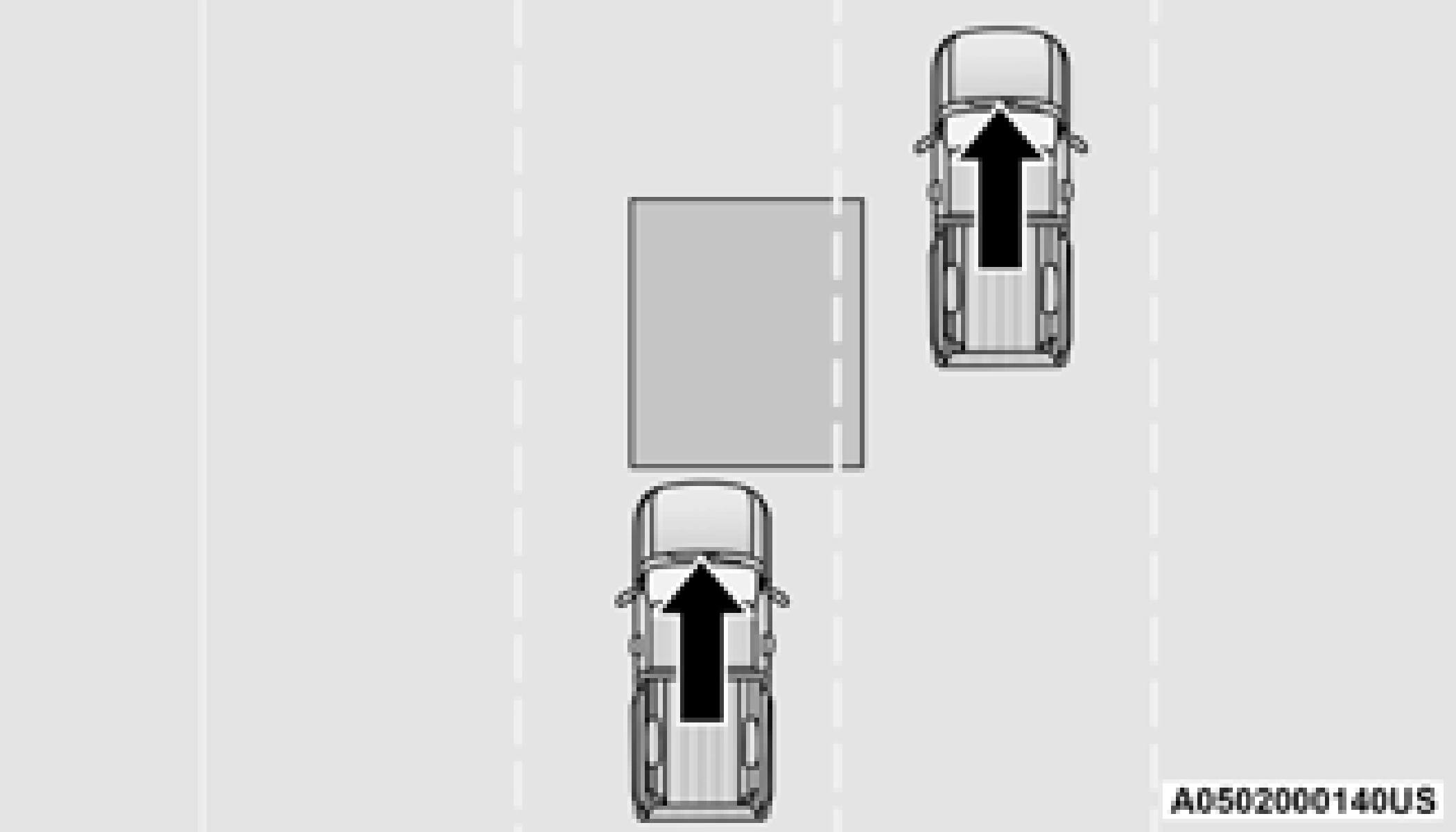
Vehicles that move into your adjacent lanes from either side of the vehicle.
Entering From The Rear
Vehicles that come up from behind your vehicle on either side and enter the rear detection zone with a relative speed of less than 30 mph
(48 km/h).
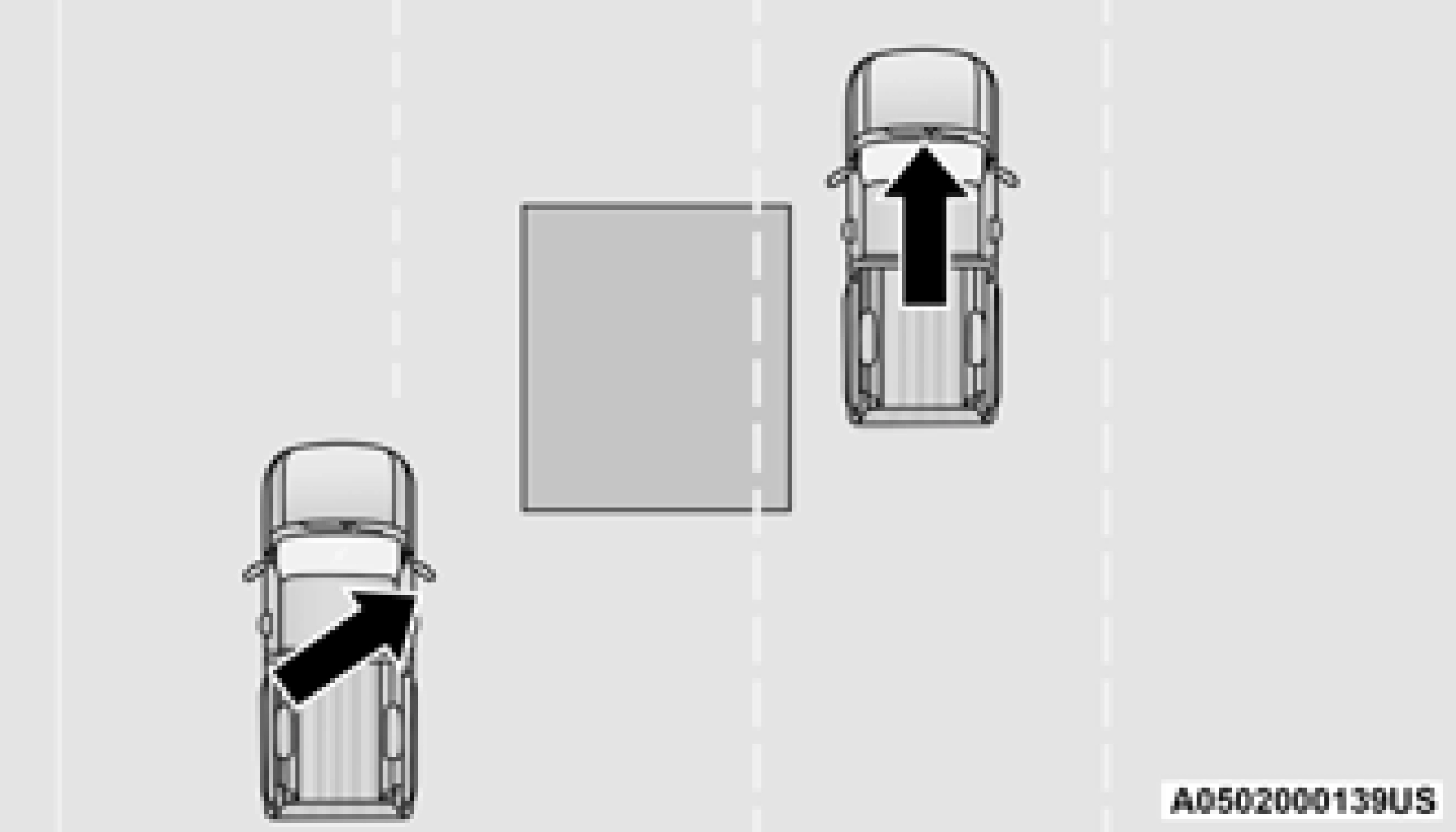
Overtaking Traffic
If you pass another vehicle slowly with a relative speed less than 15 mph (24 km/h) and the vehicle remains in the blind spot for approximately 1.5 seconds, the warning light will be illuminated. If the difference in speed between the two vehicles is greater than
15 mph (24 km/h), the warning light will not illuminate.
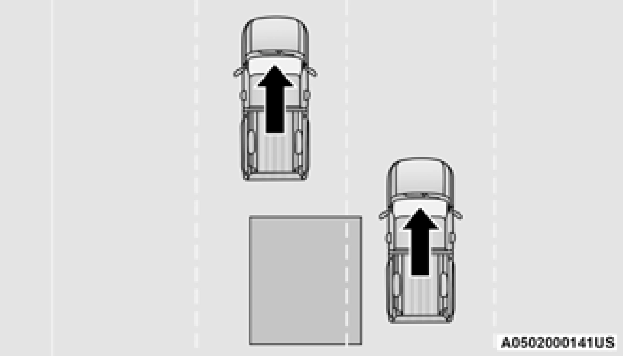
Overtaking/Passing
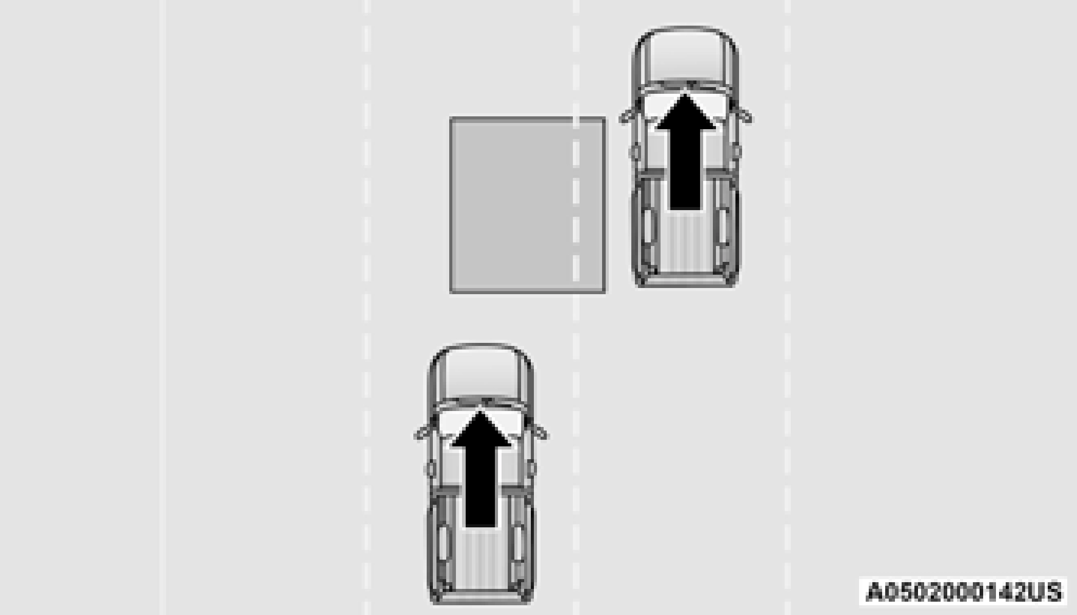
The BSM system is designed not to issue an alert on stationary objects such as guardrails, posts, walls, foliage, berms, snow banks, car washes etc. However, occasionally the system may alert on such objects. This is normal operation and your vehicle does not require service.
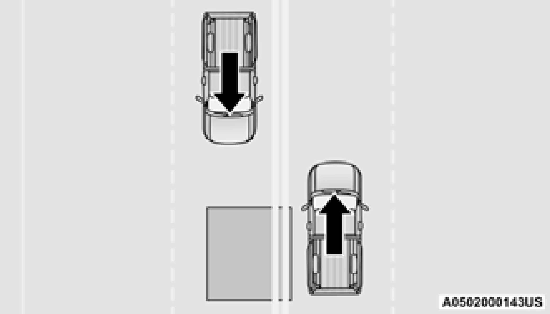
The BSM system will not alert you of objects that are traveling in the opposite direction of the vehicle in adjacent lanes page 482.
For information on how Blind Spot Monitoring functions when pulling a trailer page 322.
Rear Cross Path (RCP)
RCP is intended to aid the driver when backing out of parking spaces where their vision of oncoming vehicles may be blocked. Proceed slowly and cautiously out of the parking space until the rear end of the vehicle is exposed. The RCP system will then have a clear view of the cross traffic, and if an oncoming vehicle is detected, alert the driver.
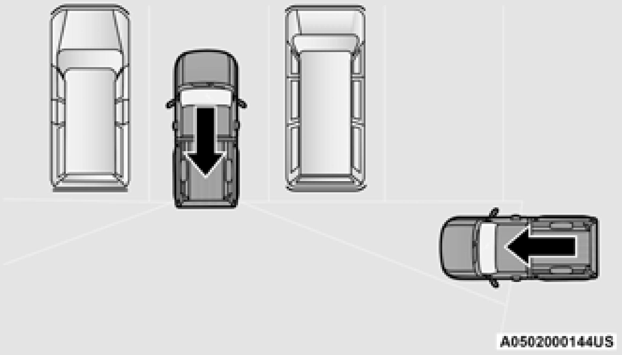
RCP monitors the rear detection zones on both sides of the vehicle, for objects that are moving toward the side of the vehicle with a minimum speed of approximately 3 mph (5 km/h), to objects moving a maximum of approximately 20 mph (32 km/h), such as in parking lot situations.
When RCP is on and the vehicle is in REVERSE (R), the driver is alerted using both the visual and audible alarms, including reducing the radio volume.
In a parking lot situation, oncoming vehicles can be blocked by vehicles parked on either side. If the sensors are blocked by other structures or vehicles, the system will not be able to alert the driver.
6
Blind Spot has three selectable modes of operation that are available in the Uconnect system.
When operating in Blind Spot Alert mode, the BSM system will provide a visual alert in the appropriate side view mirror based on a detected object. However, when the system is operating in Rear Cross Path (RCP) mode, the system will respond with both visual and audible alerts when a detected object is present. Whenever an audible alert is requested, the radio is muted.
When operating in Blind Spot Alert Lights/ Chime mode, the BSM system will provide a visual alert in the appropriate side view mirror based on a detected object. If the turn signal is then activated, and it corresponds to an alert present on that side of the vehicle, an audible chime will also be sounded. Whenever a turn signal and detected object are present on the same side at the same time, both the visual and audible alerts will be issued. In addition to the audible alert the radio (if on) will also be muted.
Whenever an audible alert is requested by the BSM system, the radio is also muted.
When the system is in RCP, the system shall respond with both visual and audible alerts when a detected object is present. Whenever an audible alert is requested, the radio is also muted. Turn/hazard signal status is ignored; the RCP state always requests the chime.
When the BSM system is turned off there will be no visual or audible alerts from either the BSM, RCP, or Trailer Merge Assist systems.
The BSM system will store the current operating mode when the vehicle is shut off. Each time the vehicle is started the previously stored mode will be recalled and used.
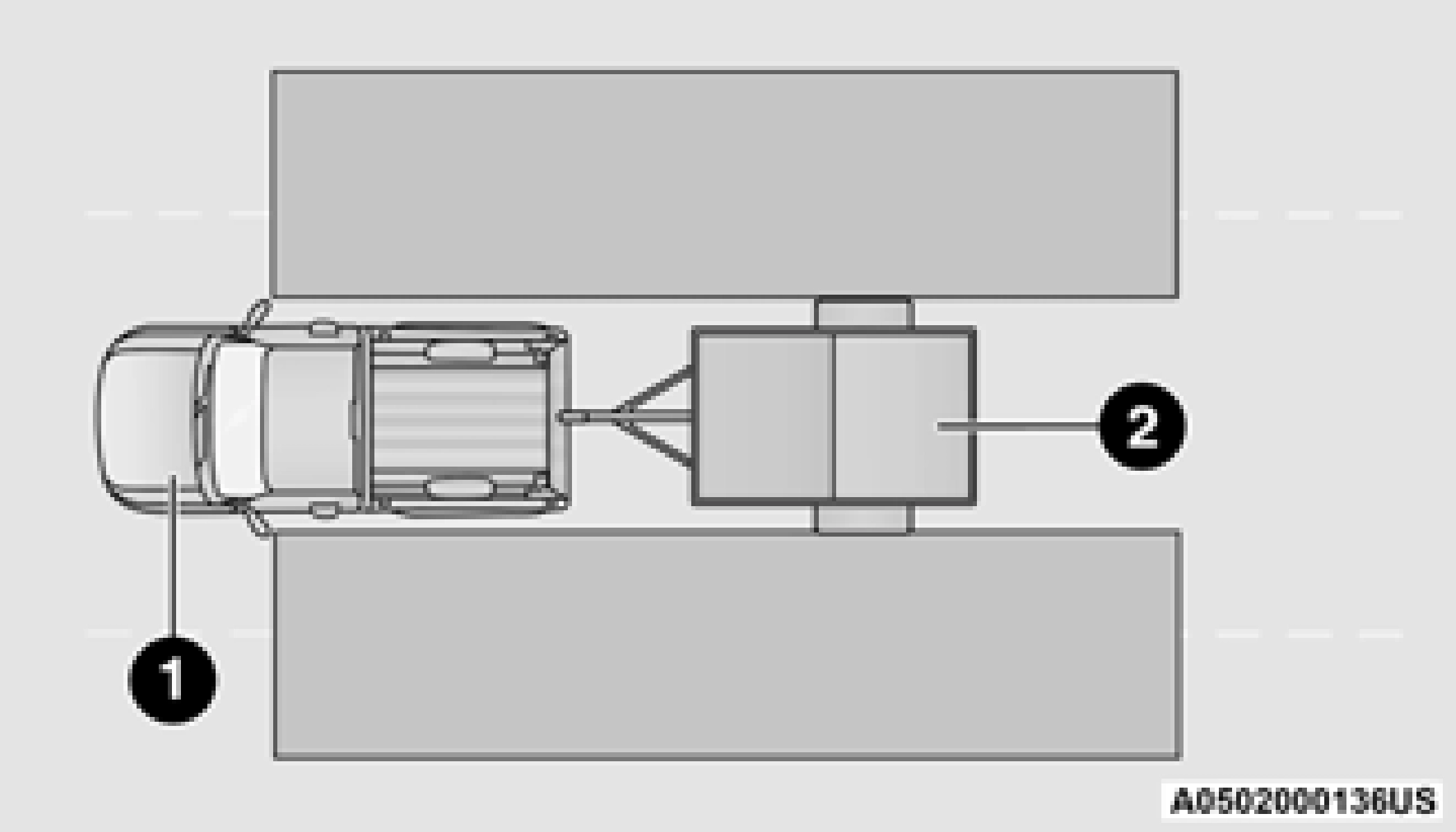
Trailer Merge Assist is a function of the Blind Spot Monitoring (BSM) system that extends the blind spot zone to work while pulling a trailer.
When Trailer Merge Assist is activated, Rear Cross Path is disabled.
Trailer Merge Assist consists of three sub functions:
There are two modes of operation for the detection of the trailer length:
a trailer will be detected using the blind spot radar within 90 seconds of forward move- ment of the vehicle. The vehicle must be moving above 6 mph (10 km/h) to activate the feature. Once the trailer has been detected, the system will default to the maximum blind spot zone until the length has been verified. You will see “Auto” in the
instrument panel cluster  .
.
 .
.Selected setting is stored when the ignition is placed in the OFF position. To change this setting, it must be selected through the Uconnect settings page 237.
Once the trailer presence has been established, the trailer length will be established (by making a 90 degree turn) and then the trailer length category (example 10-20 ft (3 m to 6 m)) will be displayed. This can take up to 30 seconds after completing the turn.
During the same ignition cycle, if the vehicle is at a standstill for a minimum of 90 seconds, a new “trailer detection request” is enabled by the system once the vehicle resumes motion.
Maximum length supported by the Trailer Merge Assist feature is 39.5 ft (12 m). Trailer length is considered the forward most portion of the trailer hitch to the rearward most portion of the body, fascia/bumper, or ramp of the trailer.
Maximum width supported by the Trailer Merge Assist feature is 8.5 ft (2.59 m). Trailer width is measured at the widest portion of the trailer and may include wheels, tires, finders, or rails.
Fifth wheel or gooseneck trailers are not supported by Trailer Merge Assist.
The ability to detect a trailer may be degraded in crowded or busy environments. Busy parking lots, narrow areas surrounded with trees, or any other crowded area may prevent the radar sensors from being able to adequately detect the trailer. The system will try to detect a trailer at every ignition cycle or 90 seconds of stand- still.
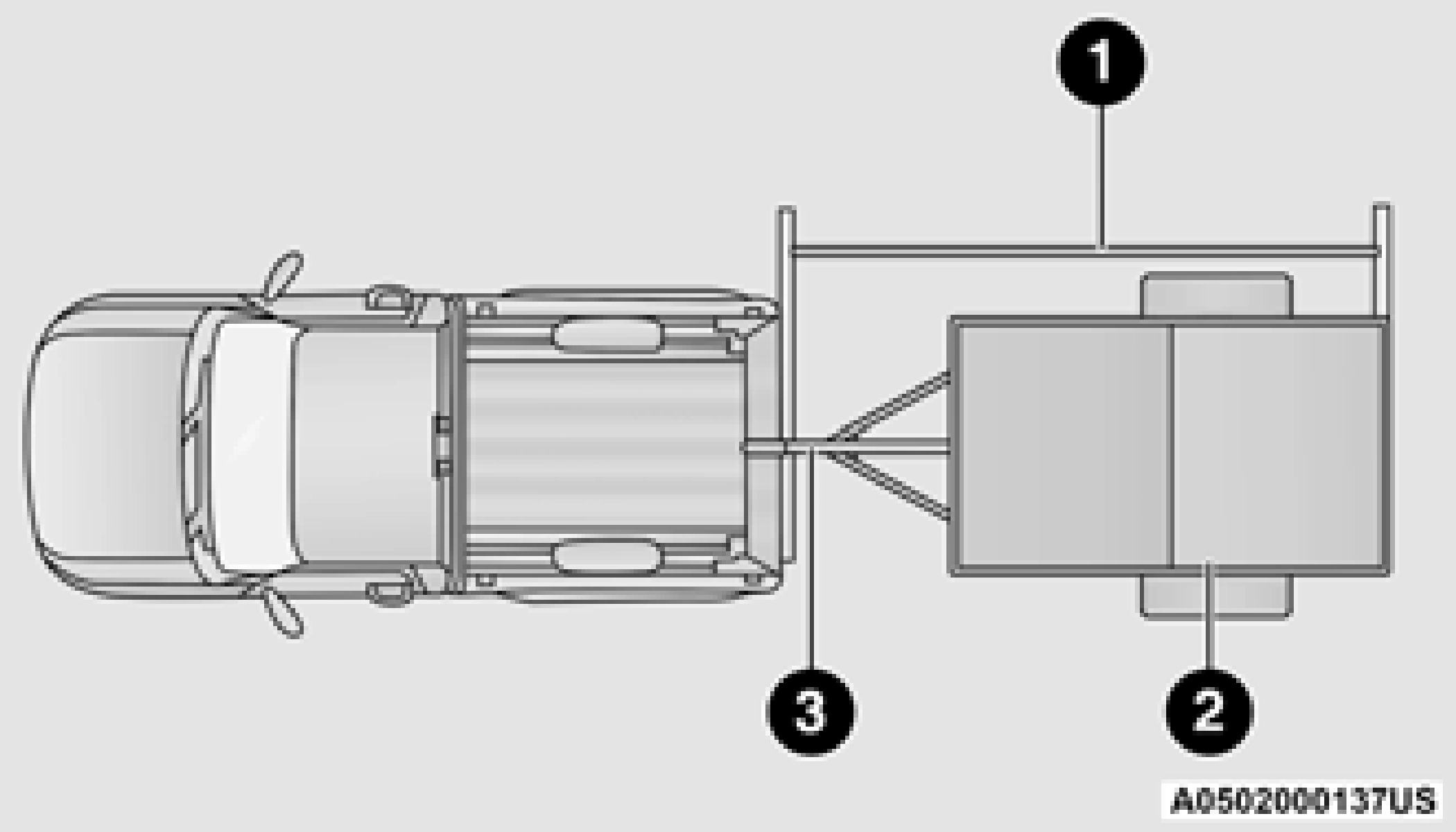
1 — Trailer Length 2 — Trailer Width 3 — Trailer Hitch
Trailer length will be identified and placed into 6
one of the following categories:
 .
.Trailer length is determined within +/- 3 ft (1 m) of actual length. Trailers that are the same size as the category limit, 10/20/30 ft (3/6/9 m), could be subject to being placed in the category above or below the correct one.
Trailer Merge Warning is the extension of the blind spot function to cover the length of the trailer, plus a safety margin, to warn the driver when there is a vehicle in the adjacent lane. The driver is alerted by the illumination of the BSM warning light located in the outside mirror on the side the other vehicle is detected on. In addition, an audible (chime) alert will be heard
the side mirror warning indicator lamps when a motorcycle or any small object remains at the side of the vehicle for extended periods of time (more than a couple of seconds).
The Blind Spot Monitoring system is only an aid to help detect objects in the blind spot zones. The BSM system is not designed to detect pedestrians, bicyclists, or animals. Even if your vehicle is equipped with the BSM system, always check your vehicle’s mirrors, glance over your shoulder, and use your turn signal before changing lanes. Failure to do so can result in serious injury or death.
potential frontal collision. The warnings and limited braking are intended to provide the driver with enough time to react, avoid or mitigate the potential collision.
FCW monitors the information from the forward looking sensors as well as the Electronic Brake Controller (EBC), to calculate the probability of a forward collision. When the system determines that a forward collision is probable, the driver will be provided with audible and visual warn- ings as well as a possible brake jerk warning.
If the driver does not take action based upon these progressive warnings, then the system will provide a limited level of active braking to help slow the vehicle and mitigate the potential forward collision. If the driver reacts to the warn- ings by braking and the system determines that the driver intends to avoid the collision by
and radio volume will be reduced page 322.
braking but has not applied sufficient brake
FORWARD COLLISION WARNING (FCW) WITH MITIGATION — IF EQUIPPED
FCW with Mitigation provides the driver with audible warnings, visual warnings (within the instrument cluster display), and may apply a brake jerk to warn the driver when it detects a
force, the system will compensate and provide additional brake force as required.
If a FCW with Mitigation event begins at a speed below 32 mph (52 km/h), the system may provide the maximum braking possible to miti- gate the potential forward collision. If the
Forward Collision Warning with Mitigation event stops the vehicle completely, the system will hold the vehicle at standstill for two seconds and then release the brakes.

When the system determines a collision with the vehicle in front of you is no longer probable, the warning message will be deactivated
page 482.
The FCW button is located in the Uconnect display in the control settings page 237.
system from warning the driver of a possible
collision with the vehicle in front. If the FCW is set to “off”, “FCW OFF” will be displayed in the instrument cluster display.
The FCW Sensitivity and Active Braking status are programmable through the Uconnect system page 237.
If the instrument cluster displays “ACC/FCW Limited Functionality” or “ACC/FCW Limited Functionality Clean Front Windshield” momentarily, there may be a condition that limits FCW functionality. Although the vehicle is still driveable under normal conditions, the active braking may not be fully available. Once the condition that limited the system performance is no longer present, the system will return to its full performance state. If the problem persists, see an authorized dealer.
If the system turns off, and the instrument cluster displays:
This indicates there is an internal system fault. Although the vehicle is still drivable under normal conditions, have the system checked by an authorized dealer.
PEB is a subsystem of the FCW system that provides the driver with audible and visual warnings in the instrument cluster display, and may apply automatic braking when it detects a potential frontal collision with a pedestrian.
If a PEB event begins at a speed below 37 mph (60 km/h), the system may provide braking to mitigate the potential collision with a pedestrian. If the PEB event stops the vehicle completely, the system will hold the vehicle at a standstill for two seconds and then release the brakes. When the system determines a collision with the pedestrian in front of you is no longer probable, the warning message will be deactivated.
The minimum speed for PEB activation is 3 mph (5 km/h).
The default status of PEB is “On.” This allows the system to warn you of a possible frontal collision with the pedestrian.
The PEB button is located in the Uconnect display in the controls settings page 237.
To turn the PEB system off, push the Pedestrian Emergency Braking button once.
To turn the PEB system back on, push the Pedestrian Emergency Braking button again.
Changing the PEB status to “Off” deactivates the system, so no warning or active braking will be available in case of a possible frontal collision with the pedestrian.
The PEB system will NOT retain the last setting selected by the driver after ignition shut down. The system will reset to the default setting when the vehicle is restarted.
TIRE PRESSURE MONITORING SYSTEM (TPMS)
TPMS will warn the driver of a low tire pressure based on the vehicle recommended cold placard pressure.
The TPMS Warning Light will illuminate in the
instrument cluster and a chime will sound when 6
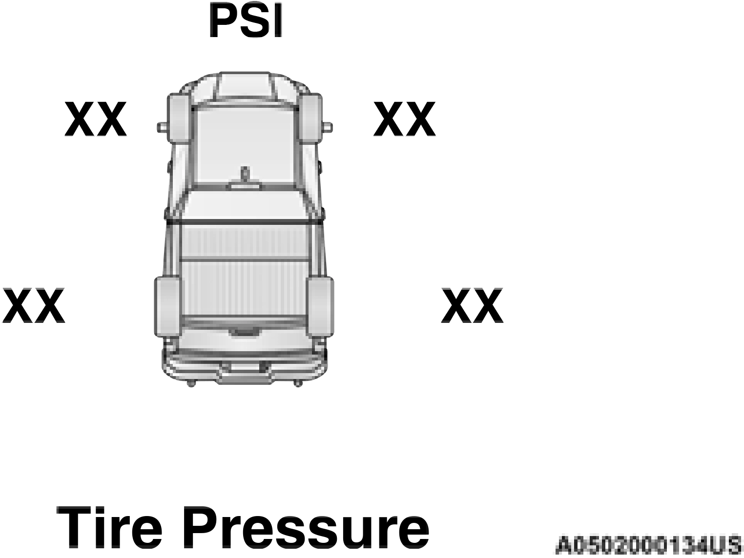
tire pressure is low in one or more of the four active road tires. In addition, the instrument cluster will display a graphic showing the pres- sure values of each tire with the low tire pres- sure values in a different color, or the Uconnect radio will display a TPMS message; when this occurs you must increase the tire pressure to the recommended cold placard pressure in order for the TPMS Warning Light to turn off.
The tire pressure will vary with temperature by about 1 psi (7 kPa) for every 12°F (6.5°C). This means that when the outside temperature decreases, the tire pressure will decrease. Tire
pressure should always be set based on cold inflation tire pressure. This is defined as the tire pressure after the vehicle has not been driven for at least three hours, or driven less than
1 mile (1.6 km) after a three hour period. The cold tire inflation pressure must not exceed the maximum inflation pressure molded into the tire sidewall. The tire pressure will also increase as the vehicle is driven — this is normal and there should be no adjustment for this increased pressure.
See page 443 on how to properly inflate the vehicle’s tires.
The TPMS will warn the driver of a low tire pressure if the tire pressure falls below the low-pressure warning limit for any reason, including low temperature effects and natural pressure loss through the tire page 482.
The TPMS will continue to warn the driver of low tire pressure as long as the condition exists, and will not turn off until the tire pressure is at or above the recommended cold placard pressure. Once the low TPMS Warning Light illuminates, increase the tire pressure to the recommended cold placard pressure in order for the TPMS Warning Light to turn off. The system will automatically update and the TPMS
Warning Light will turn off once the system receives the updated tire pressures. The vehicle may need to be driven for up to 20 minutes above 15 mph (24 km/h) in order for the TPMS to receive this information.
When filling warm tires, the tire pressure may need to be increased up to an additional 4 psi (28 kPa) above the recommended cold placard pressure in order to turn the TPMS Warning Light off.
For example, your vehicle may have a recommended cold (parked for more than three hours) placard pressure of 30 psi (207 kPa). If the ambient temperature is 68°F (20°C) and the measured tire pressure is 27 psi (186 kPa), a temperature drop to 20°F (-7°C) will decrease the tire pressure to approximately 23 psi (158 kPa). This tire pressure is sufficiently low enough to turn on the TPMS Warning Light. Driving the vehicle may cause the tire pressure to rise to approximately 27 psi (186 kPa), but the TPMS Warning Light will still be on. In this situation, the TPMS Warning Light will turn off only after the tires are inflated to the vehicle’s recommended cold placard pressure value.
The Tire Pressure Monitoring System (TPMS) uses wireless technology with wheel rim mounted electronic sensors to monitor tire pressure levels. Sensors, mounted to each wheel as part of the valve stem, transmit tire pressure readings to the receiver module.
It is particularly important for you to check the tire pressure in all of the tires on your vehicle monthly and to maintain the proper pressure.
The TPMS consists of the following components:
 The Tire Pressure Monitoring System (TPMS) Warning Light will illuminate in the instrument cluster and a chime will sound when tire pressure is low in
one or more of the four active road tires. In addition, the instrument cluster will display a graphic showing the pressure values of each tire with the low tire pressure values in a different color. An "Inflate to XX" message will also be displayed.
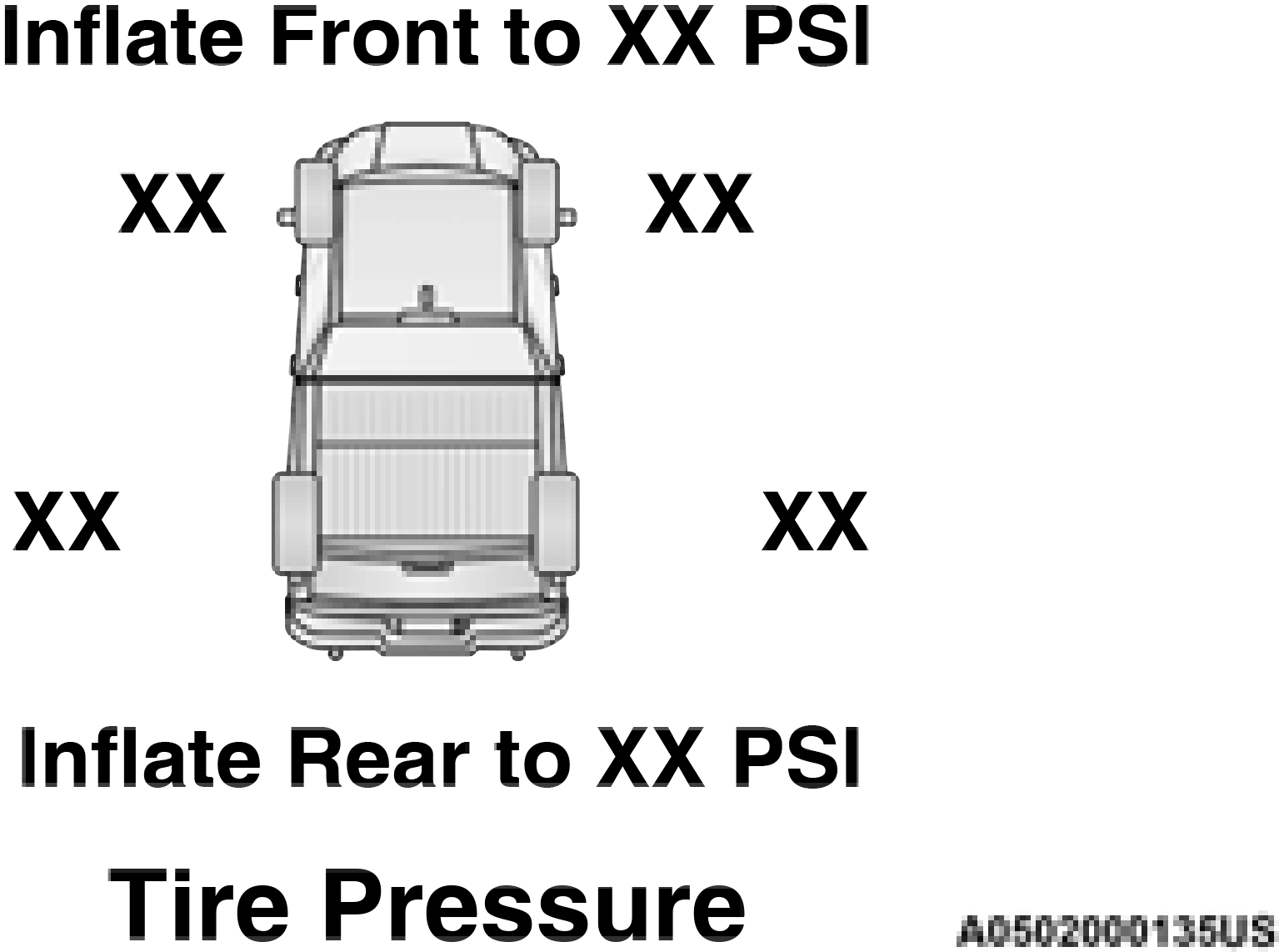
Should this occur, you should stop as soon as possible and inflate the tires with a low pressure condition (those in a different color in the instrument cluster graphic) to the vehicle’s recommended cold placard pressure inflation value as shown in the "Inflate to XX" message. Once the system receives the updated tire pressures, the system will automatically update, the graphic display in the instrument cluster will return to its original color, and the Tire Pressure Monitoring System Warning Light will turn off. The vehicle may need to be driven for up to 20 minutes above 15 mph (24 km/h) in order for the TPMS to receive this information.
When filling warm tires, the tire pressure may need to be increased up to an additional 4 psi (28 kPa) above the recommended cold placard pressure in order to turn the Tire Pressure Moni- toring System Warning Light off.
If a system fault is detected, the Tire Pressure Monitoring System (TPMS) Warning Light will flash on and off for 75 seconds and then remain on solid. The system fault will also sound a chime. In addition, the instrument cluster will
display a "SERVICE TPMS SYSTEM" message for a minimum of five seconds and then display dashes (--) in place of the pressure value to indicate which sensor is not being received.
If the ignition switch is cycled, this sequence will repeat, providing the system fault still exists. If the system fault no longer exists, the Tire Pressure Monitoring System Warning Light will no longer flash, and the "SERVICE TPMS SYSTEM" message will no longer display, and a pressure value will display in place of the dashes. A system fault can occur due to any of the following:
A system fault may occur due to an incorrect TPMS sensor location condition. When a system fault occurs due to an incorrect TPMS sensor location, the Tire Pressure Monitoring System (TPMS) Warning Light will flash on and off for 75 seconds and then remain on solid. The system fault will also sound a chime. In addition, the instrument cluster will display a Tire Pressure Temporarily Unavailable message in place of the tire pressure display screen. If the ignition switch is cycled, this sequence will repeat, providing the system fault still exists. If the system fault no longer exists, the “Tire Pressure Monitoring System Warning Light” will no longer flash and the tire pressure display screen will be displayed showing the tire pressure values the correct locations.
warning limit, upon the next ignition switch cycle, the Tire Pressure Monitoring System (TPMS) Warning Light and a “LOW TIRE” message will remain on and a chime will sound. In addition, the graphic in the instru- ment cluster will still display a pressure value in a different color and an “Inflate to XX” message.
This feature notifies the user when the placard tire pressure is attained while inflating or deflating the tire.
You may choose to disable or enable the Tire Fill Alert feature through use of the Uconnect Settings in the radio.
The system will be activated when a positive increase in tire pressure is detected by the TPMS while inflating the tire. The ignition must be in the RUN mode, with the transmission in PARK.
It is not required to have the engine running to enter Tire Fill Alert mode.
The hazard lamps will come on to confirm the 6
vehicle is in Tire Fill Alert mode.
When Tire Fill Alert mode is entered, the tire pressure display screen will be displayed in the instrument cluster.
If the hazard lamps do not come on while inflating the tire, the TPMS sensor may be out of range preventing the TPMS sensor signal from being received. In this case, the vehicle may need to be moved either forward or backward slightly to exit the null spot.
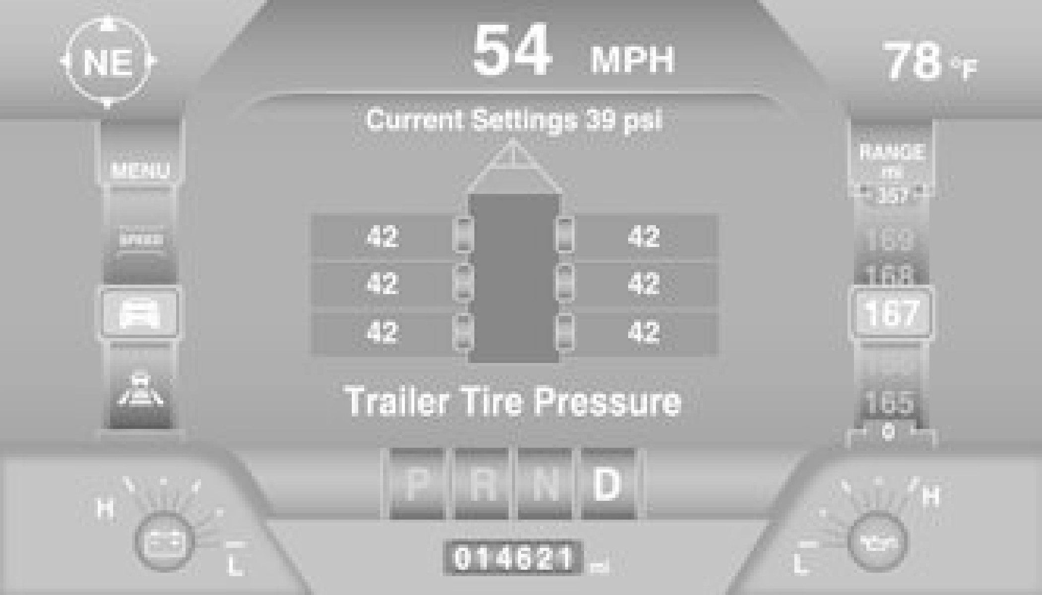
The Trailer Tire Pressure Monitoring System (TTPMS) is a feature that displays the trailer tire pressure values and warns the driver of a low tire pressure event based on the drivers set target tire pressure value, through TTPMS settings found in the radio.
The TTPMS monitors the pressure of each tire and warns the driver through the instrument cluster, when either a low tire pressure
condition falls below 25% of the drivers set pressure or if a system malfunction occurs. The instrument cluster will display the actual tire pressure or dashes for each of the trailer tires in the correct trailer position, based on trailer configuration. The TTPMS can support up to 12 trailer tires per configured trailer on up to four configurable trailers page 237.
Trailer Tire Pressure Sensor Pairing
In order use this feature, the provided tire pressure sensors must be installed in the desired trailer tires and the sensors must be paired to the truck. If the target trailer requires more than the provided four sensors, additional sensors can be purchased at an authorized Ram dealership.
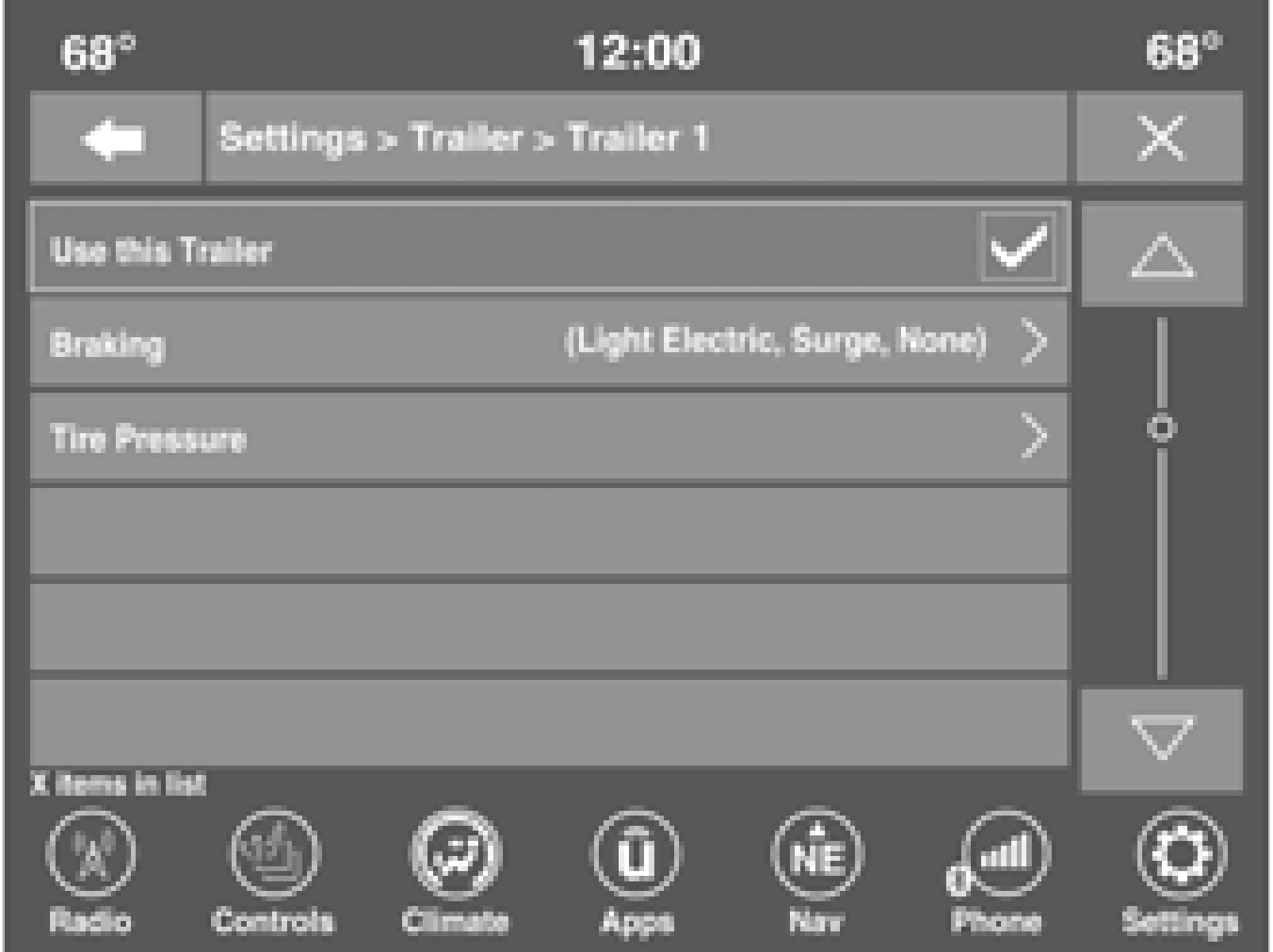
With the sensors installed and the trailer near or connected to your Ram truck, initiate the pairing process by entering the settings menu in the radio and selecting trailer. Select the desired trailer profile to pair to, open the “Tire Pressure” menu, and hit “Setup All Tires”
page 237.
The vehicle may not be driven until the pairing process is complete.
Trailer Tire Pressure Pairing
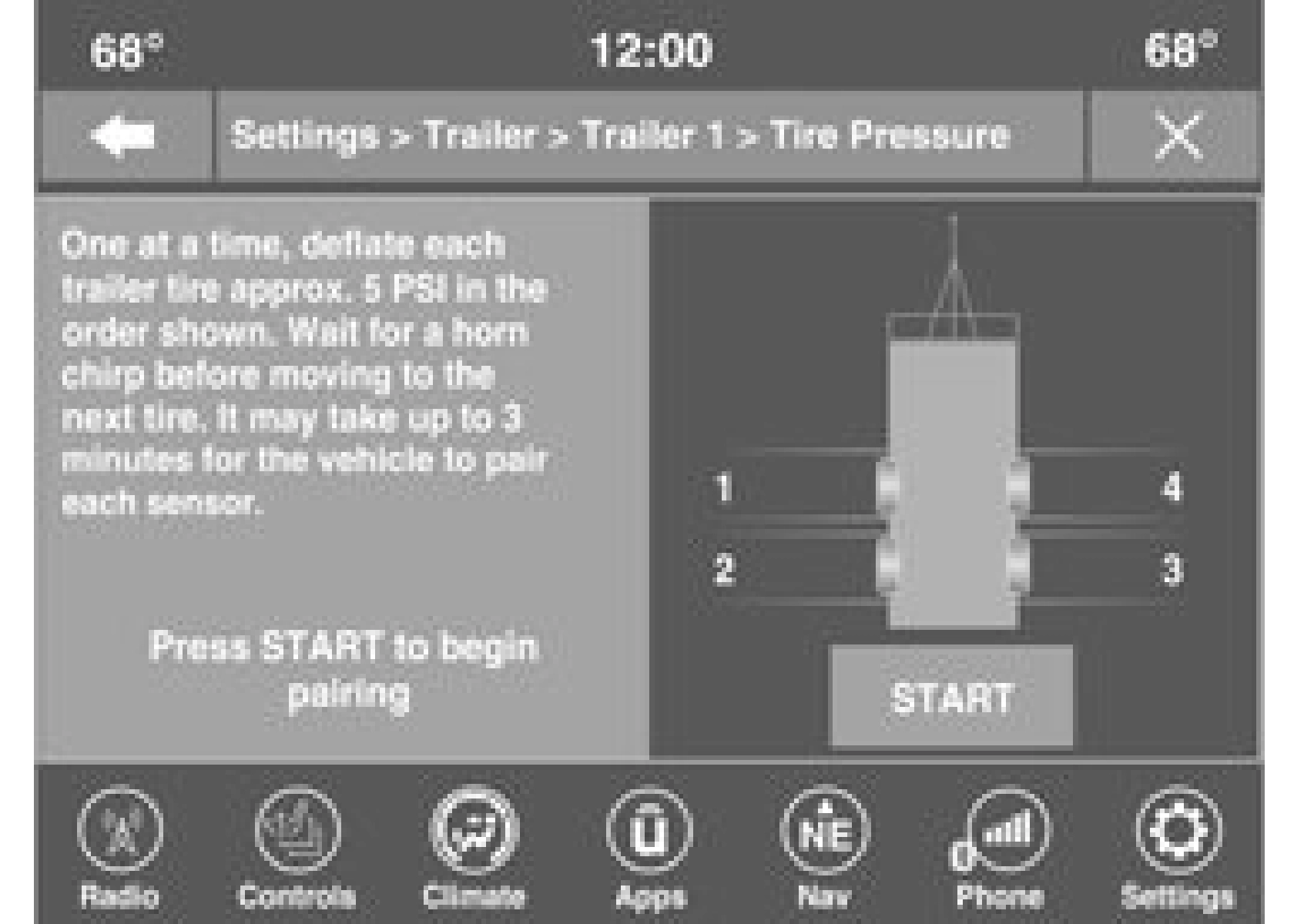
Follow the on screen prompts to select the number of axles (1 - 3), the number of trailer tires (2, 4, 6, 8, or 12), and the set trailer tire pressure. The range is selectable anywhere between 25-125 PSI (172-862 kPa).
Once PSI (kPa) is programmed, the pairing screen appears. Tire sensors must be paired in order shown. Starting with Tire 1, deflate tire by 5 PSI (34 kPa) and wait for a horn chirp. It may take up to three minutes for the chirp to occur, indicating that the sensor has paired. Repeat process on each tire, in order, until complete. Do not exit the pairing screen until process is complete. If pairing was unsuccessful, a double horn chirp will sound, and a prompt on the touchscreen will allow you to retry the procedure; “Retry” will only appear when setup
fails. Each tire must be successfully paired during a single pairing process to receive the success screen.
If the pairing process times out after three minutes of no communication with a sensor, a double horn chip will occur indicating the pairing has failed and a message will display on the radio indicating the process was unsuc- cessful. Under certain circumstances, the double horn chirp may continue to happen every three minutes indicating the failed pairing. If this happens, the horn chirping may be canceled by cycling the ignition button OFF and then back to RUN position.
When a tire pressure low in one or more of the active road tires is detected, the instrument cluster will display a message stating “Trailer Tire Pressure Low”. The instrument cluster will then display the TTPMS graphic showing the pressure values of each tire with the low tire pressure values in a different color.
Should this occur, you should stop as soon as possible and inflate the tires with a low pressure
condition (those in a different color in the instrument cluster graphic) to the customer programmed target tire pressure value as shown at the top of the TTPMS instrument cluster graphic. Once the tire(s) are inflated, the system will automatically update the graphic display in the instrument cluster, returning to its original color. The vehicle may need to be driven for up to 10 minutes above 15 mph (24 km/h) in order for the TTPMS to receive the updated information.
If a system fault is detected, the instrument
cluster will display a “Trailer Tire Pressure 6
System Service Required” message for a
minimum of five seconds.
Once the system fault is corrected the "Trailer Tire Pressure System Service Required" message will no longer be displayed. The vehicle may need to be driven for up to
10 minutes above 15 mph (24 km/h) in order for the TTPMS to receive the trailer tire pressure information.
A “Trailer Tire Pressure System Not Configured” message will be displayed in the instrument cluster on the TTPMS instrument cluster graphic when a trailer number is selected that has not had trailer tire pressure sensors paired. To correct this condition, see page 237.
The “Trailer Sensors Detected Do Not Match Active Trailer” message will be displayed in the instrument cluster when the trailer sensors being received by the TTPMS module do not match the trailer sensors paired to the current trailer number selected. This message will be displayed when the sensors being received completely match the sensors paired to another trailer number configured in the TTPMS module.
To correct this condition, the correct trailer number must be selected in the radio
page 237.
Download Manual