VEHICLE MAINTENANCE
An authorized dealer has the qualified service personnel, special tools, and equipment to perform all service operations in an expert manner. Service Manuals are available which include detailed service information for your vehicle. Refer to these Service Manuals before attempting any procedure yourself.
Intentional tampering with emissions control systems may void your warranty and could result in civil penalties being assessed against you.
ENGINE OIL
Engine Oil Selection
For best performance and maximum protection under all types of operating conditions, the manufacturer recommends engine oils that meet the requirements of FCA Material Standard. For the proper engine oil selection page 390.
Hemi engines (5.7L) at times can tick right after startup and then quiet down after approxi- mately 30 seconds. This is normal and will not harm the engine. This characteristic can be caused by short drive cycles. For example, if the vehicle is started then shut off after driving a short distance. Upon restarting, you may experi- ence a ticking sound. Other causes could be if
the vehicle is unused for an extended period of time, incorrect oil, extended oil changes or extended idling. If the engine continues to tick or if the Malfunction Indicator Light (MIL) comes on, see the nearest authorized dealer.
 This symbol means that the oil has been certified by the American Petroleum Institute (API). FCA only recommends API Certified engine oils.
This symbol certifies 0W-20, 5W-20, 0W-30, 5W-30 and 10W-30 engine oils.
You may use synthetic engine oils provided the recommended oil quality requirements are met, and the recommended maintenance intervals for oil and filter changes are followed.
Synthetic engine oils which do not have both the engine oil certification mark and the correct SAE viscosity grade number should not be used.
FCA strongly recommends against the addition of any additives (other than leak detection dyes) to the engine oil. Engine oil is an engineered product and its performance may be impaired by supplemental additives.
Care should be taken in disposing of used engine oil and oil filters from your vehicle. Used oil and oil filters, indiscriminately discarded, can present a problem to the environment. Contact an authorized dealer, service station or governmental agency for advice on how and where used oil and oil filters can be safely discarded in your area.
ENGINE OIL FILTER
The engine oil filter should be replaced with a new filter at every engine oil change.
A full-flow type disposable oil filter should be used for replacement. The quality of
replacement filters varies considerably. Only high quality Mopar certified filters should be used.
ENGINE AIR CLEANER FILTER
For the proper maintenance intervals
page 330.
Be sure to follow the “Severe Duty Conditions” maintenance interval if applicable.
The quality of replacement filters varies considerably. Only high quality Mopar certified filters should be used.
Inspect engine air cleaner filter for dirt and/or debris, if you find evidence of either dirt or debris, change the engine air cleaner filter.
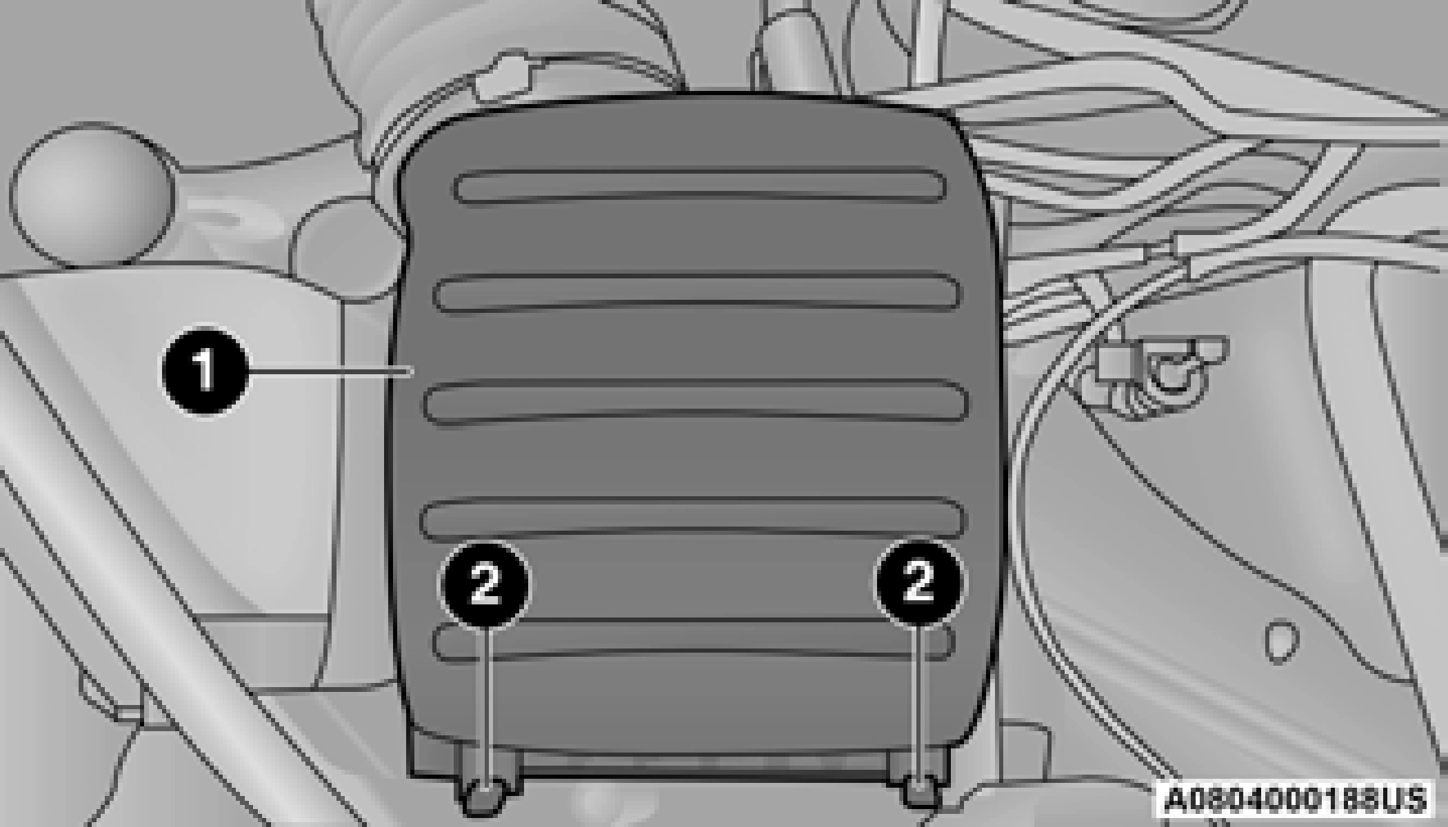
1 — Engine Air Cleaner Filter Cover 2 — Spring Clips
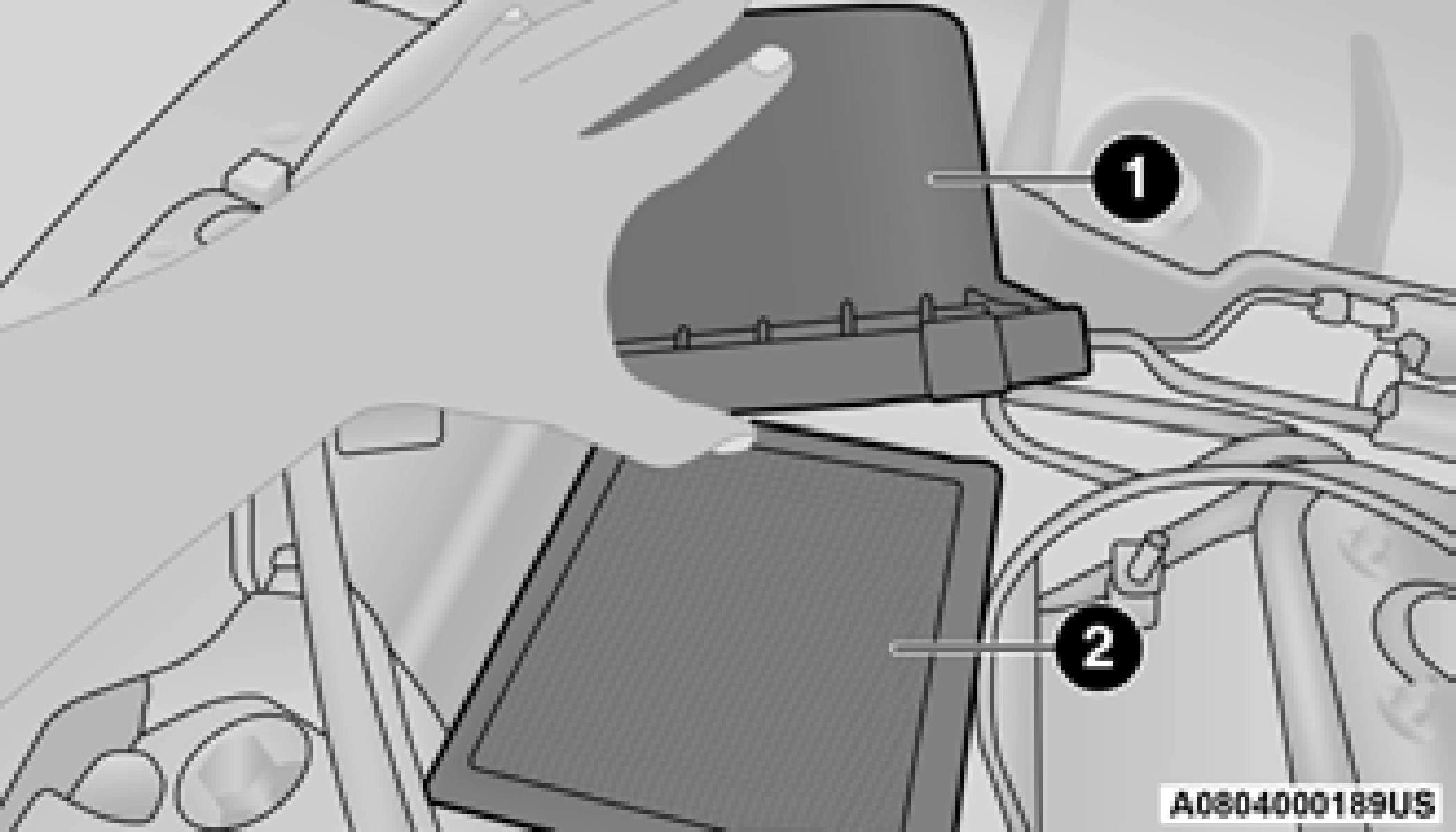
1 — Engine Air Cleaner Filter Cover 2 — Engine Air Cleaner Filter
Inspect and clean the housing if dirt or debris is present before replacing the engine air cleaner filter.
AIR CONDITIONER MAINTENANCE
For best possible performance, the air conditioner should be checked and serviced by an authorized dealer at the start of each warm season. This service should include cleaning of the condenser fins and a performance test.
Drive belt tension should also be checked at this time.
R-134a Air Conditioning Refrigerant is a hydrofluorocarbon (HFC) that is an
ozone-friendly substance. FCA recommends that air conditioning service be performed by an authorized dealer or other service facilities using recovery and recycling equipment.
Use only FCA approved A/C system PAG compressor oil and refrigerants.
R-1234yf Air Conditioning Refrigerant is a hydrofluoroolefin (HFO) that is endorsed by the Environmental Protection Agency and is an ozone-friendly substance with a low
global-warming potential. FCA recommends that air conditioning service be performed by an authorized dealer using recovery and recycling equipment.
Use only FCA approved A/C system PAG compressor oil, and refrigerants.
For the proper maintenance intervals
page 330.
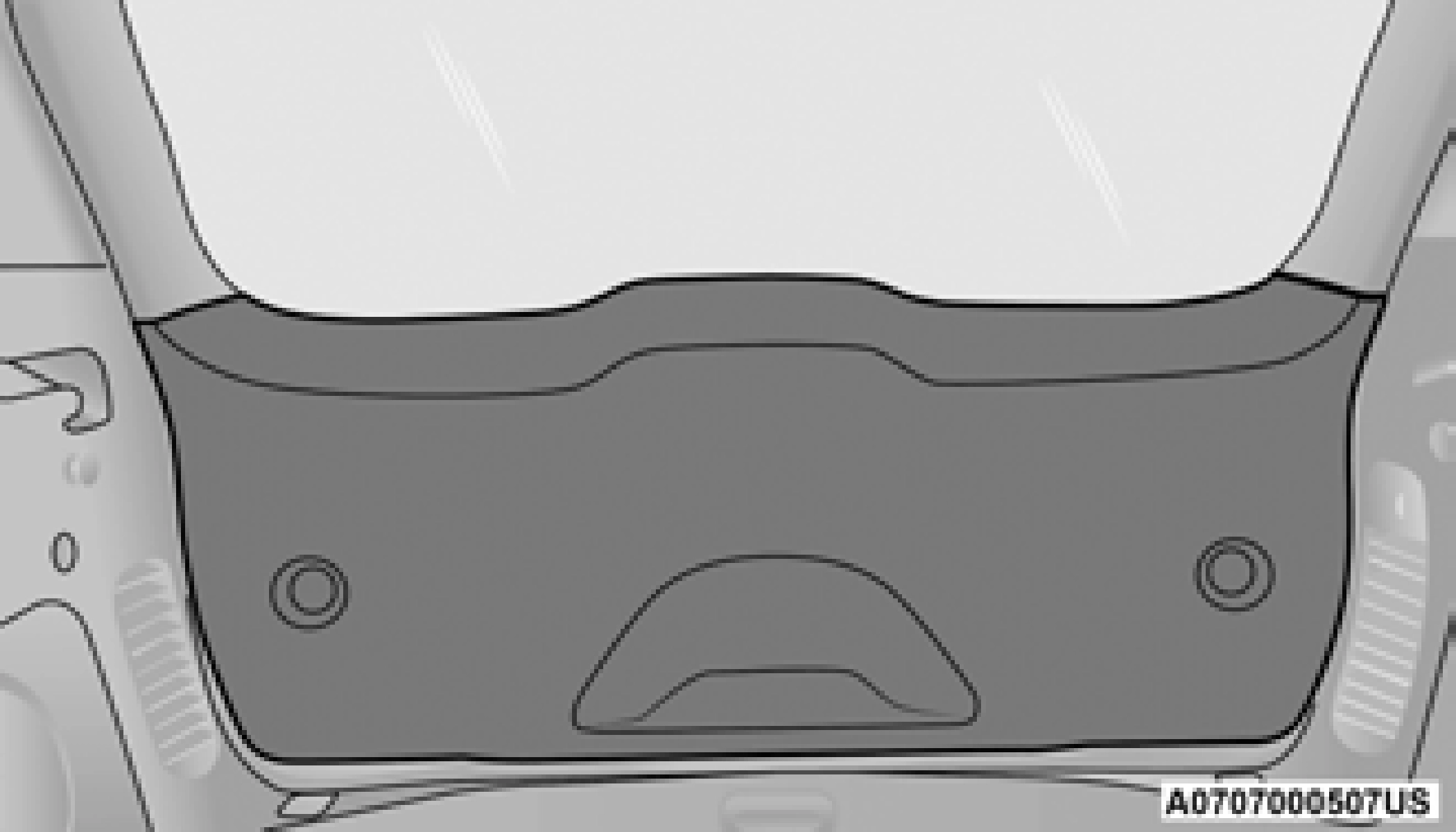
The A/C air filter is located in the fresh air inlet behind the glove compartment. Perform the following procedure to replace the filter:
When disengaging the glove compartment door from its hinges, there will be some resistance.
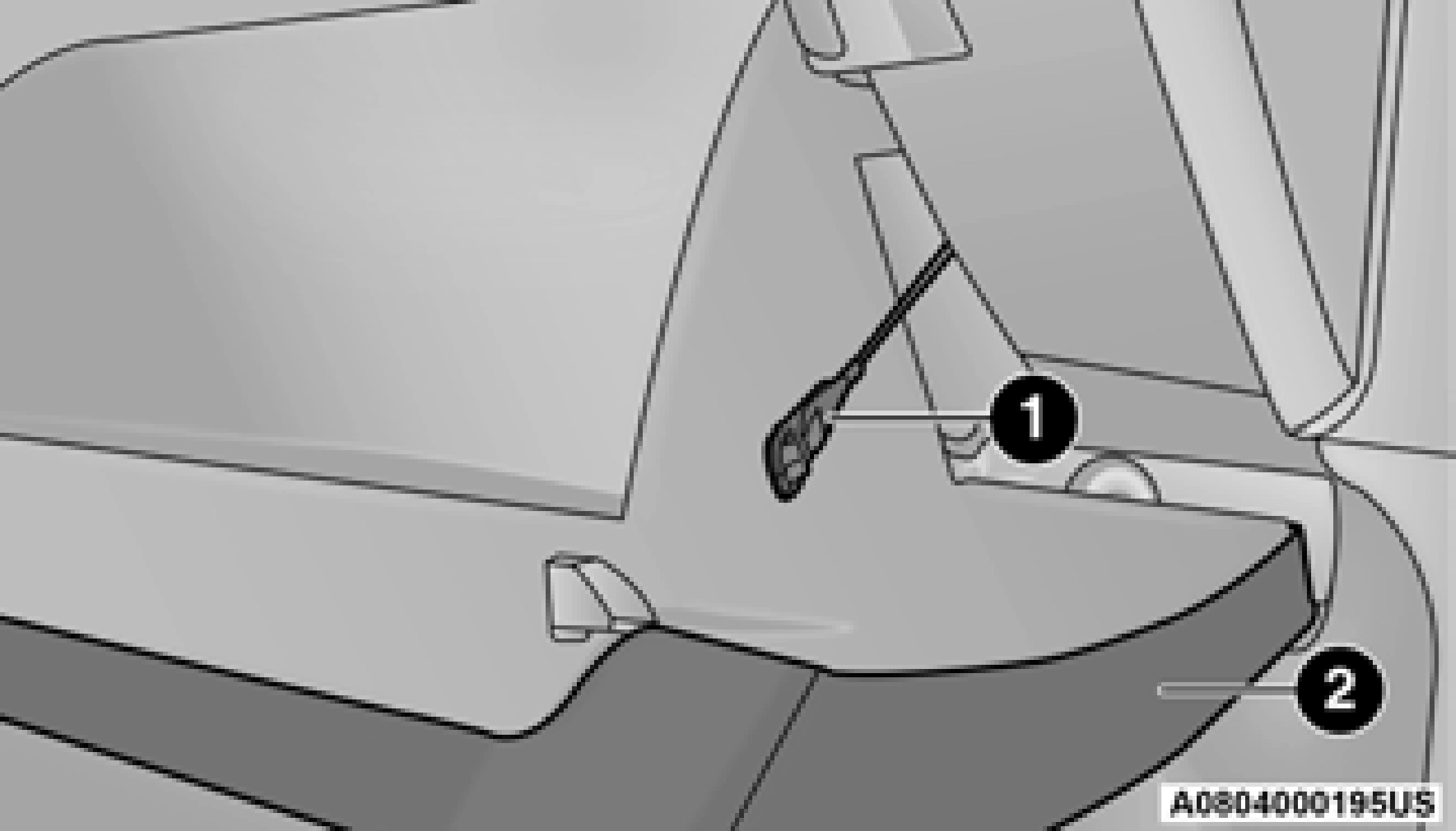
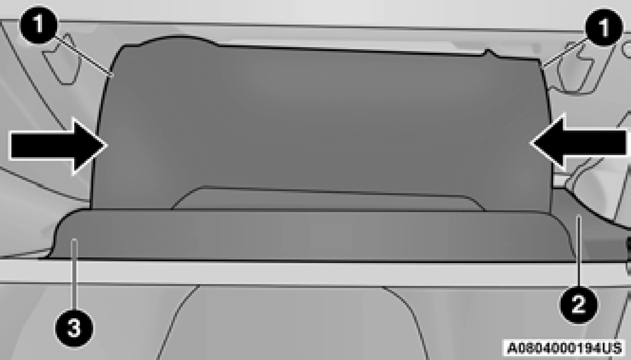
Right Side Of Glove Compartment 1 — Glove Compartment Tension Tether 2 — Glove Compartment Door
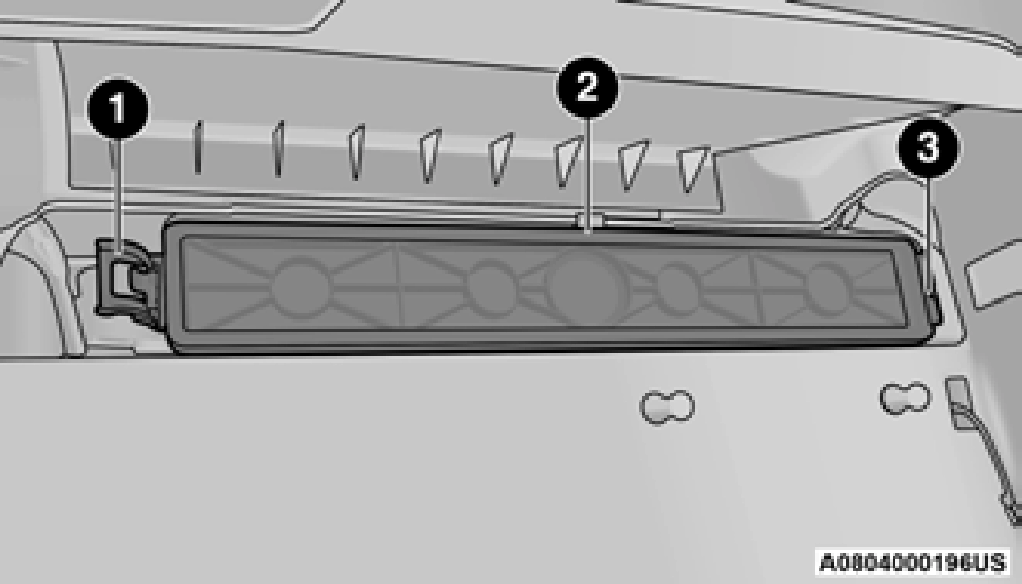
1 — Retaining Tab 2 — Mid Way Snap
3 — Filter Cover Hinge
Ensure the glove compartment door hinges and glove compartment travel stops are fully engaged.
ACCESSORY DRIVE BELT INSPECTION
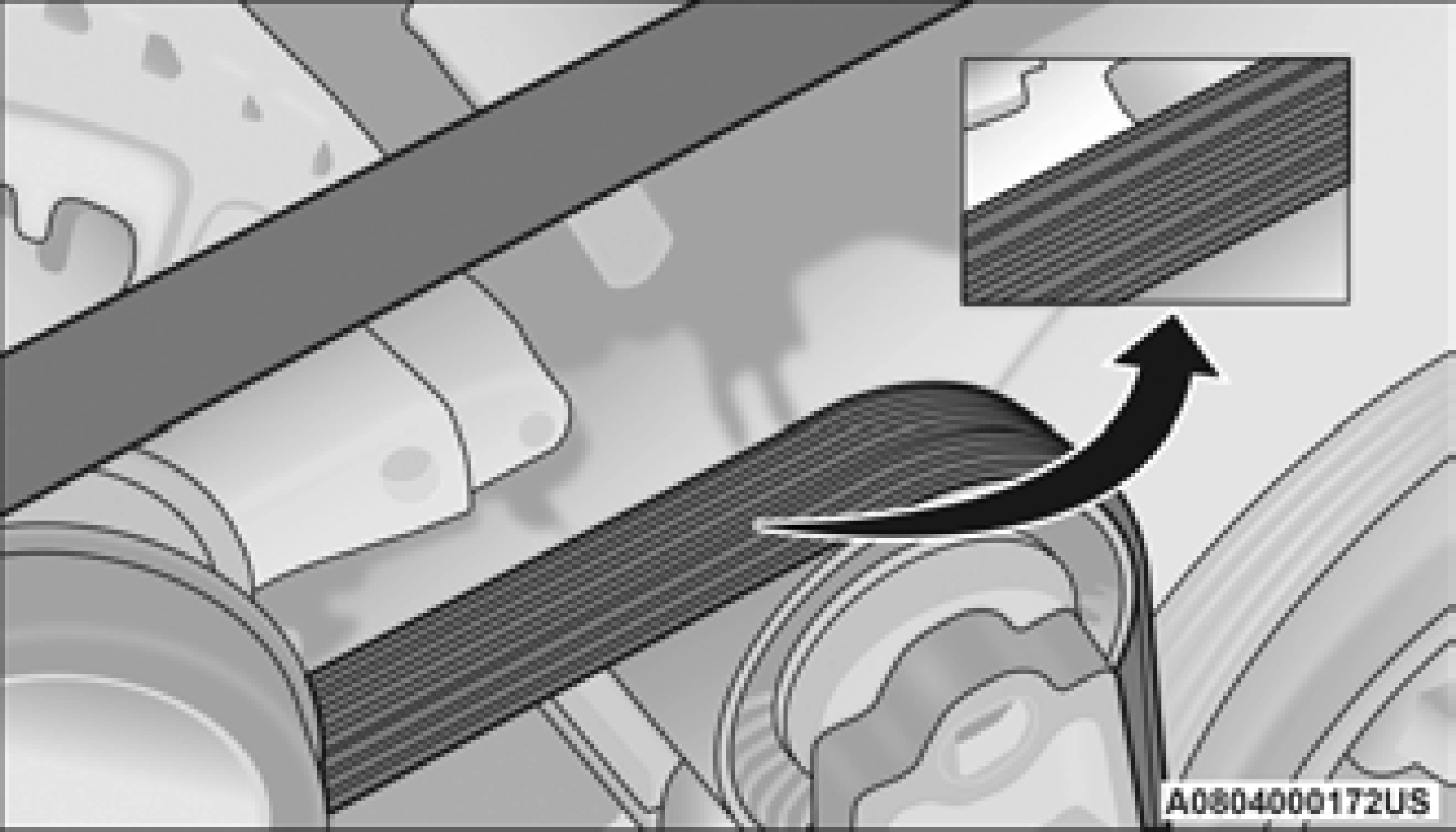
8
When inspecting accessory drive belts, small
cracks that run across the ribbed surface of the belt from rib to rib, are considered normal. This is not a reason to replace belt. However, cracks running along a rib (not across) are not normal. Any belt with cracks running along a rib must be replaced. Also have the belt replaced if it has excessive wear, frayed cords or severe glazing.
Conditions that would require replacement:
Some conditions can be caused by a faulty component such as a belt pulley. Belt pulleys should be carefully inspected for damage and proper alignment.
Belt replacement on some models requires the use of special tools, we recommend having your vehicle serviced at an authorized dealer.
BODY LUBRICATION
Locks and all body pivot points, including such items as seat tracks, door hinge pivot points and rollers, liftgate, tailgate, decklid, sliding doors and hood hinges, should be lubricated periodically use a lithium-based grease, such as Mopar Spray White Lube to ensure quiet, easy operation and to protect against rust and wear. Prior to the application of any lubricant, the parts concerned should be wiped clean to remove dust and grit; after lubricating, excess oil and grease should be removed. Particular attention should also be given to hood latching components to ensure proper function. When performing other underhood services, the hood latch, release mechanism and safety catch should be cleaned and lubricated.
The external lock cylinders should be lubricated twice a year, preferably in the Autumn and Spring. Apply a small amount of a high quality lubricant, such as Mopar Lock Cylinder Lubricant directly into the lock cylinder.
WINDSHIELD WIPER BLADES
Clean the rubber edges of the wiper blades and the windshield periodically with a sponge or soft cloth and a mild nonabrasive cleaner. This will remove accumulations of salt or road film.
Operation of the wipers on dry glass for long periods may cause deterioration of the wiper blades. Always use washer fluid when using the wipers to remove salt or dirt from a dry windshield.
Avoid using the wiper blades to remove frost or ice from the windshield. Keep the blade rubber out of contact with petroleum products such as engine oil, gasoline, etc.
Life expectancy of wiper blades varies depending on geographical area and frequency of use. If chattering, marks, water lines or wet spots are present, clean the wiper blades or replace as necessary.
The wiper blades and wiper arms should be inspected periodically, not just when wiper performance problems are experienced. This inspection should include the following points:
If a wiper blade or wiper arm is damaged, replace the affected wiper arm or blade with a new unit. Do not attempt to repair a wiper arm or blade that is damaged.
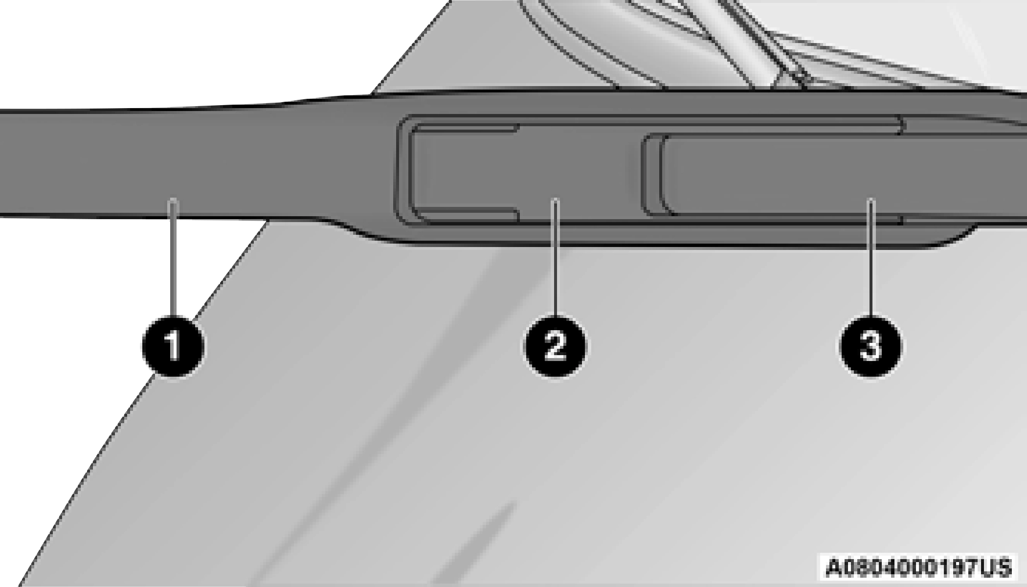
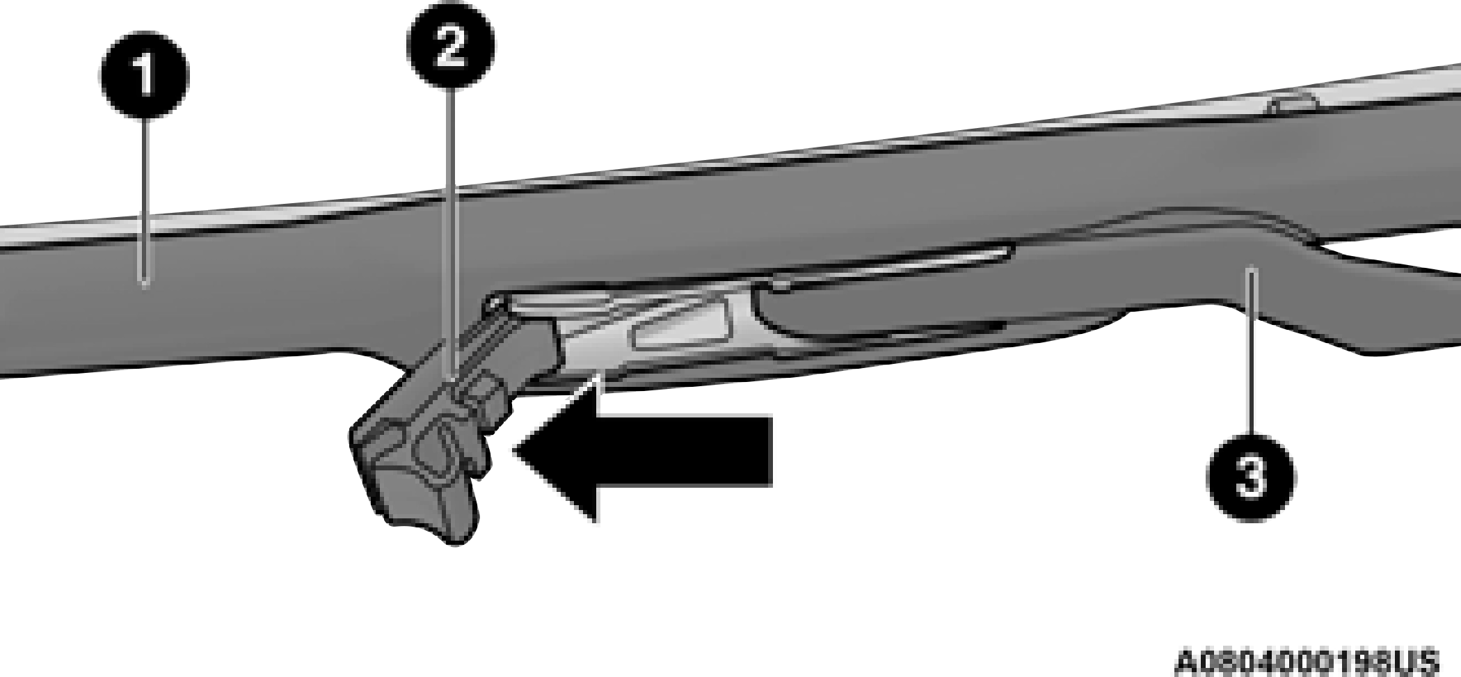
1 — Wiper Blade 2 — Release Tab
3 — Wiper Arm 8

1 — Wiper Blade 2 — Wiper Arm 3 — Release Tab
The rear wiper arm cannot be fully raised off the glass unless the wiper arm pivot cap is unsnapped first. Attempting to fully raise the rear wiper arm without unsnapping the wiper arm pivot cap may damage the vehicle.
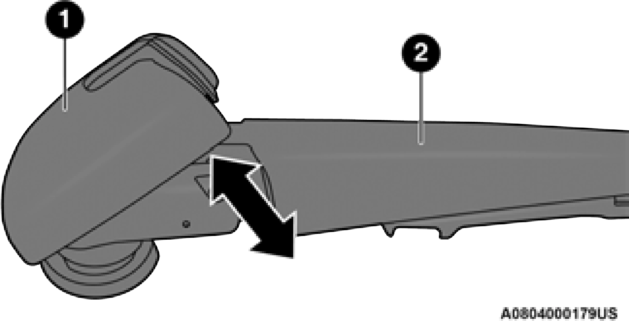
1 — Wiper Arm Pivot Cap 2 — Wiper Arm
Resistance will be accompanied by an audible snap.
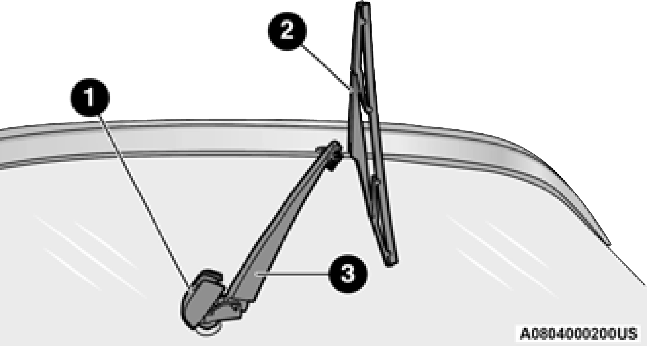
1 — Wiper Arm Pivot Cap 2 — Wiper Blade
3 — Wiper Arm
The rear wiper arm cannot be fully raised off the glass unless the wiper arm pivot cap is unsnapped first. Attempting to fully raise the rear wiper arm without unsnapping the wiper arm pivot cap may damage the vehicle.
EXHAUST SYSTEM
The best protection against carbon monoxide entry into the vehicle body is a properly maintained engine exhaust system.
If you notice a change in the sound of the exhaust system; or if the exhaust fumes can be detected inside the vehicle; or when the underside or rear of the vehicle is damaged;
have an authorized technician inspect the complete exhaust system and adjacent body areas for broken, damaged, deteriorated, or mispositioned parts. Open seams or loose connections could permit exhaust fumes to seep into the passenger compartment. In addition, have the exhaust system inspected each time the vehicle is raised for lubrication or oil change. Replace as required.
8
Under normal operating conditions, the catalytic converter will not require maintenance. However, it is important to keep the engine properly tuned to ensure proper catalyst operation and prevent possible catalyst damage.
Intentional tampering with emissions control systems can result in civil penalties being assessed against you.
In unusual situations involving grossly malfunctioning engine operation, a scorching odor may suggest severe and abnormal catalyst overheating. If this occurs, stop the vehicle, turn off the engine and allow it to cool. Service, including a tune-up to FCA specifications, should be obtained immediately.
To minimize the possibility of catalytic converter damage:
COOLING SYSTEM
Check the engine coolant (antifreeze) protection every 12 months (before the onset of freezing weather, where applicable). If the engine coolant is dirty, the system should be drained, flushed, and refilled with fresh Organic Additive Technology (OAT) coolant (conforming to MS.90032) by an authorized dealer. Check the front of the A/C condenser for any accumulation of bugs, leaves, etc. If dirty, clean by gently spraying water from a garden hose vertically down the face of the condenser.
Check the engine cooling system hoses for brittle rubber, cracking, tears, cuts, and tightness of the connection at the coolant recovery bottle and radiator. Inspect the entire system for leaks. DO NOT REMOVE THE COOLANT PRESSURE CAP WHEN THE COOLING SYSTEM IS HOT.
Some vehicles require special tools to add coolant properly. Failure to fill these systems properly could lead to severe internal engine damage. If any coolant is needed to be added to the system, please contact an authorized dealer.
If the engine coolant (antifreeze) is dirty or contains visible sediment, have an authorized dealer clean and flush with Organic Additive Technology (OAT) coolant (conforming to MS.90032).
For the proper maintenance intervals
page 330.
For further information page 390. NOTE:
non-OAT engine coolant is introduced into the cooling system in an emergency, the cooling system will need to be drained, flushed, and refilled with fresh OAT coolant (conforming to MS.90032), by an authorized dealer as soon as possible.
Your vehicle has been built with an improved
engine coolant (OAT coolant conforming to 8
MS.90032) that allows extended maintenance intervals. This engine coolant (antifreeze) can be used up to 10 years or 150,000 miles (240,000 km) before replacement. To prevent reducing this extended maintenance period, it is important that you use the same engine coolant (OAT coolant conforming to MS.90032) throughout the life of your vehicle.
Please review these recommendations for using Organic Additive Technology (OAT) engine coolant that meets the requirements of FCA Material Standard MS.90032. When adding engine coolant:
(240,000 km) Formula OAT that meets the requirements of FCA Material Standard MS.90032.
according to the temperatures occurring in the area where the vehicle is operated.
The cap must be fully tightened to prevent loss of engine coolant (antifreeze), and to ensure that engine coolant will return to the radiator from the coolant expansion bottle/recovery tank (if equipped).
The cap should be inspected and cleaned if there is any accumulation of foreign material on the sealing surfaces.
Used ethylene glycol-based coolant (antifreeze) is a regulated substance requiring proper disposal. Check with your local authorities to determine the disposal rules for your community. To prevent ingestion by animals or children, do not store ethylene glycol-based coolant in open containers or allow it to remain in puddles on the ground, clean up any ground spills immediately. If ingested by a child or pet, seek emergency assistance immediately.
The coolant bottle provides a quick visual method for determining that the coolant level is adequate. With the engine OFF and cold, the level of the engine coolant (antifreeze) in the bottle should be between the ranges indicated on the bottle.
The radiator normally remains completely full, so there is no need to remove the radiator/ coolant pressure cap unless checking for engine coolant freeze point or replacing coolant. Advise your service attendant of this. As long as the engine operating temperature is satisfactory, the coolant bottle need only be checked once a month.
When additional engine coolant is needed to maintain the proper level, only OAT coolant that meets the requirements of FCA Material Standard MS.90032 should be added to the coolant bottle. Do not overfill.
When the vehicle is stopped after a few miles/ kilometers of operation, you may observe vapor coming from the front of the engine compart- ment. This is normally a result of moisture from
rain, snow, or high humidity accumulating on the radiator and being vaporized when the ther- mostat opens, allowing hot engine coolant (anti- freeze) to enter the radiator.
If an examination of your engine compartment shows no evidence of radiator or hose leaks, the vehicle may be safely driven. The vapor will soon dissipate.
BRAKE SYSTEM
In order to ensure brake system performance, all brake system components should be inspected periodically. For the proper maintenance intervals page 330.
8
Fluid Level Check — Brake Master Cylinder The fluid level of the master cylinder should be checked whenever the vehicle is serviced, or
immediately if the brake system warning light is
on. If necessary, add fluid to bring level within the designated marks on the side of the reservoir of the brake master cylinder. Be sure to clean the top of the master cylinder area before removing cap. With disc brakes, fluid level can be expected to fall as the brake pads wear. Brake fluid level should be checked when pads are replaced. If the brake fluid is abnormally low, check the system for leaks. For further information page 391.
(Continued)
AUTOMATIC TRANSMISSION
FCA strongly recommends against using any special additives in the transmission. Automatic Transmission Fluid (ATF) is an engineered product and its performance may be impaired by supplemental additives. Therefore, do not add any fluid additives to the transmission.
Avoid using transmission sealers as they may adversely affect seals.
The fluid level is preset at the factory and does not require adjustment under normal operating conditions. Routine fluid level checks are not required; therefore the transmission has no dipstick. An authorized dealer can check the transmission fluid level using special service tools. If you notice fluid leakage or transmission
malfunction, visit an authorized dealer immediately to have the transmission fluid level checked. Operating the vehicle with an improper fluid level can cause severe transmission damage.
Under normal operating conditions, the fluid installed at the factory will provide satisfactory lubrication for the life of the vehicle.
Routine fluid and filter changes are not required. However, change the fluid and filter if the fluid becomes contaminated (with water, etc.), or if the transmission is disassembled for any reason.
It is important to use the proper transmission fluid to ensure optimum transmission performance and life. Use only FCA's specified
transmission fluid page 391. It is important to maintain the transmission fluid at the correct level using the recommended fluid.
No chemical flushes should be used in any transmission; only the approved lubricant should be used.
FRONT/REAR AXLE FLUID
For normal service, periodic fluid level checks are not required. When the vehicle is serviced for other reasons, the exterior surfaces of the axle assembly should be inspected. If gear oil leakage is suspected inspect the fluid level.
The front axle oil level needs to be no lower than 1/8 inch (3 mm) below the bottom of the fill hole.
The front axle fill and drain plugs should be tightened to 22 to 29 ft lbs (30 to 40 N·m).
The rear axle oil level needs to be no lower than 1/8 inch (3 mm) below the bottom of the fill hole.
The rear axle fill and drain plugs should be tightened to 22 to 29 ft lbs (30 to 40 N·m).
Use only the FCA's recommended fluid
page 391.
TRANSFER CASE
For normal service, periodic fluid level checks are not required. When the vehicle is serviced for other reasons the exterior surfaces of the transfer case assembly should be inspected. If oil leakage is suspected inspect the fluid level.
With the vehicle in a level position, fill the transfer case to bottom edge of fill plug opening.
First remove fill plug, then remove drain plug. Recommended tightening torque for drain and fill plugs is 15 to 25 ft lbs (20 to 34 N·m).
Use only the FCA's recommended fluid
page 391.
FUSES
(Continued)
The fuses protect electrical systems against excessive current.
When a device does not work, you must check the fuse element inside the blade fuse for a break/melt.
Also, please be aware that when using power outlets for extended periods of time with the engine off may result in vehicle battery discharge.
Underhood Fuses
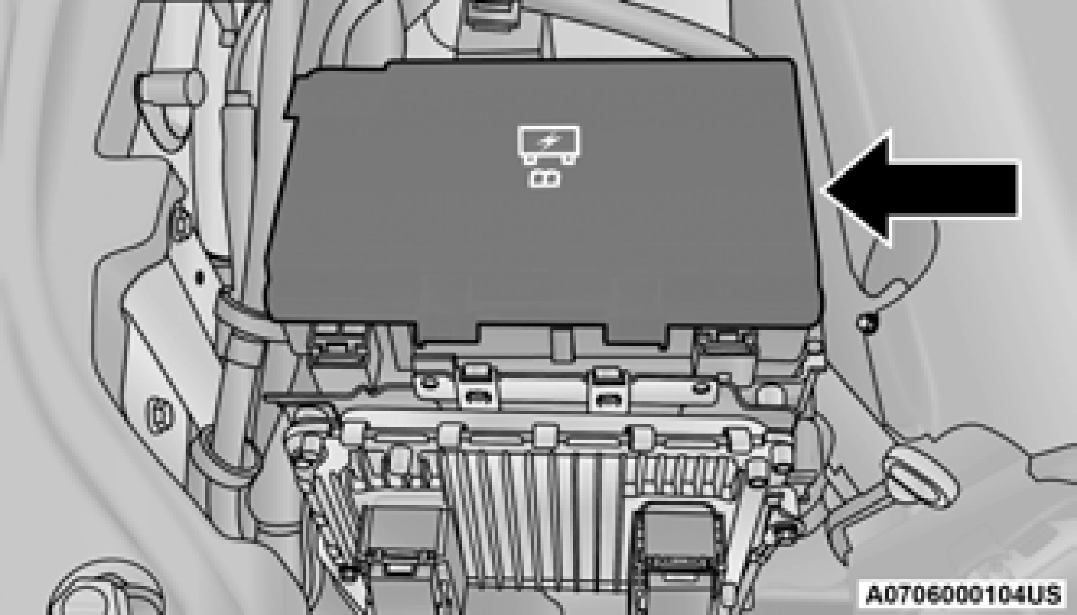 The Power Distribution Center is located in the engine compartment on the passenger’s side, next to the battery terminal posts. This center contains cartridge fuses, micro fuses, relays, and circuit breakers. A description of each fuse and component may be stamped on the inside cover, otherwise the cavity number of each fuse is stamped on the inside cover that corresponds
to the following chart. Power Distribution Center
8
|
Cavity |
Cartridge Fuse |
Micro Fuse |
Description |
|
F13 |
40 Amp Green |
— |
Blower Motor Front |
|
F14 |
40 Amp Green |
— |
Body Controller #4/Exterior Lighting #1 |
|
F15 |
40 Amp Green |
— |
Low Temperature Radiator (LTR) Engine Cooling Pump — If Equipped |
|
F17 |
30 Amp Pink |
— |
Headlamp Washer — If Equipped |
|
F19 |
20 Amp Blue |
— |
Headrest Solenoid — If Equipped |
|
F20 |
30 Amp Pink |
— |
Passenger Door Module |
|
F22 |
20 Amp Blue |
— |
Engine Control Module |
|
F23 |
30 Amp Pink |
— |
Interior Lights #1 |
|
F24 |
30 Amp Pink |
— |
Driver Door Module |
|
F25 |
30 Amp Pink |
— |
Front Wipers |
|
F26 |
30 Amp Pink |
— |
Anti-lock Brakes/Stability Control Module, ECU and Valves |
|
F28 |
20 Amp Blue |
— |
Trailer Tow Backup Lights — If Equipped |
|
F29 |
20 Amp Blue |
— |
Trailer Tow Parking Lights — If Equipped |
|
F30 |
30 Amp Pink |
— |
Trailer Tow (Receptacle) / Trailer Tow (Separate E-Brake) / Trailer Tow (BUX) — If Equipped |
|
F32 |
30 Amp Pink |
— |
Drive Train Control Module |
|
F34 |
30 Amp Pink |
— |
Slip Differential Control — If Equipped |
|
F35 |
30 Amp Pink |
— |
Sunroof - If Equipped |
|
F36 |
30 Amp Pink |
— |
Rear Defroster |
|
F37 |
25 Amp Clear |
— |
Rear Blower Motor — If Equipped |
|
F38 |
30 Amp Pink |
— |
Power Inverter 115 Volt AC — If Equipped |
8
|
Cavity |
Cartridge Fuse |
Micro Fuse |
Description |
|
F67 |
— |
15 Amp Blue |
CD/DVD/UCI Port/USB Charging Port |
|
F68 |
— |
20 Amp Yellow |
Rear Wiper Motor |
|
F69 |
— |
15 Amp Blue |
Spotlight Feed — If Equipped |
|
F70 |
— |
20 Amp Yellow |
Fuel Pump Motor |
|
F71 |
— |
30 Amp Green |
Amplifier/ANCM — If Equipped |
|
F72 |
— |
10 Amp Red |
ECM |
|
F73 |
— |
15 Amp Blue |
HID Headlamp RT — If Equipped |
|
F75 |
— |
10 Amp Red |
Dual Batt Control — If Equipped |
|
F76 |
— |
10 Amp Red |
Anti-lock Brakes/Electronic Stability Control |
|
F77 |
— |
10 Amp Red |
Drivetrain Control Module/Front Axle Disconnect Module — If Equipped |
|
F78 |
— |
10 Amp Red |
Engine Control Module/Electric Power Steering |
|
F80 |
— |
10 Amp Red |
Universal Garage Door Opener/Anti-Intrusion Module — If Equipped/ Siren — If Equipped |
|
F81 |
— |
20 Amp Yellow |
Trailer Tow Right Turn/Stop Lights — If Equipped |
|
F82 |
— |
10 Amp Red |
Steering Column Control Module/Cruise Control/DTV — If Equipped |
|
F83 |
— |
10 Amp Red |
Fuel Door |
|
F84 |
— |
15 Amp Blue |
Instrument Cluster |
|
F85 |
— |
10 Amp Red |
Airbag Module |
|
F86 |
— |
10 Amp Red |
Airbag Module |
|
F87 |
— |
10 Amp Red |
Air Suspension — If Equipped |
|
F88 |
— |
15 Amp Blue |
Instrument Panel Cluster/SGW/ITBM — If Equipped |
8
|
CAUTION! |
|
When installing the power distribution center cover, it is important to ensure the cover is properly positioned and fully latched. Failure to do so may allow water to get into the power distribution center and possibly result in an electrical system failure.
When replacing a blown fuse, it is important to use only a fuse having the correct amperage rating. The use of a fuse with a rating other than indi- cated may result in a dangerous electrical system overload. If a properly rated fuse continues to blow, it indicates a problem in the circuit that must be corrected.
|
BULB REPLACEMENT
See an authorized dealer for LED bulb replacement.
|
Interior Bulbs |
|
|
Bulb Name |
Bulb Number |
|
Glove Compartment Lamp |
194 |
|
Grab Handle Lamp |
L002825W5W |
|
Overhead Console Reading Lamps |
VT4976 |
|
Rear Cargo Lamp |
214—2 |
|
Visor Vanity Lamp |
V26377 |
|
Underpanel Courtesy Lamps |
906 |
|
Instrument Cluster (General Illumination) |
103 |
|
Telltale/Hazard Lamp |
74 |
8
High Intensity Discharge Headlamps (HID) — If Equipped
The headlamps are a type of high voltage discharge tube. High voltage can remain in the circuit even with the headlamp switched off and the key removed. Because of this, you should not attempt to service a headlamp bulb yourself. If a headlamp bulb fails, take your vehicle to an authorized dealer for service.
Lens fogging can occur under certain atmo- spheric conditions. This will usually clear as atmospheric conditions change to allow the condensation to change back to vapor. Turning the lamps on will usually accelerate the clearing process.
See below steps to replace:
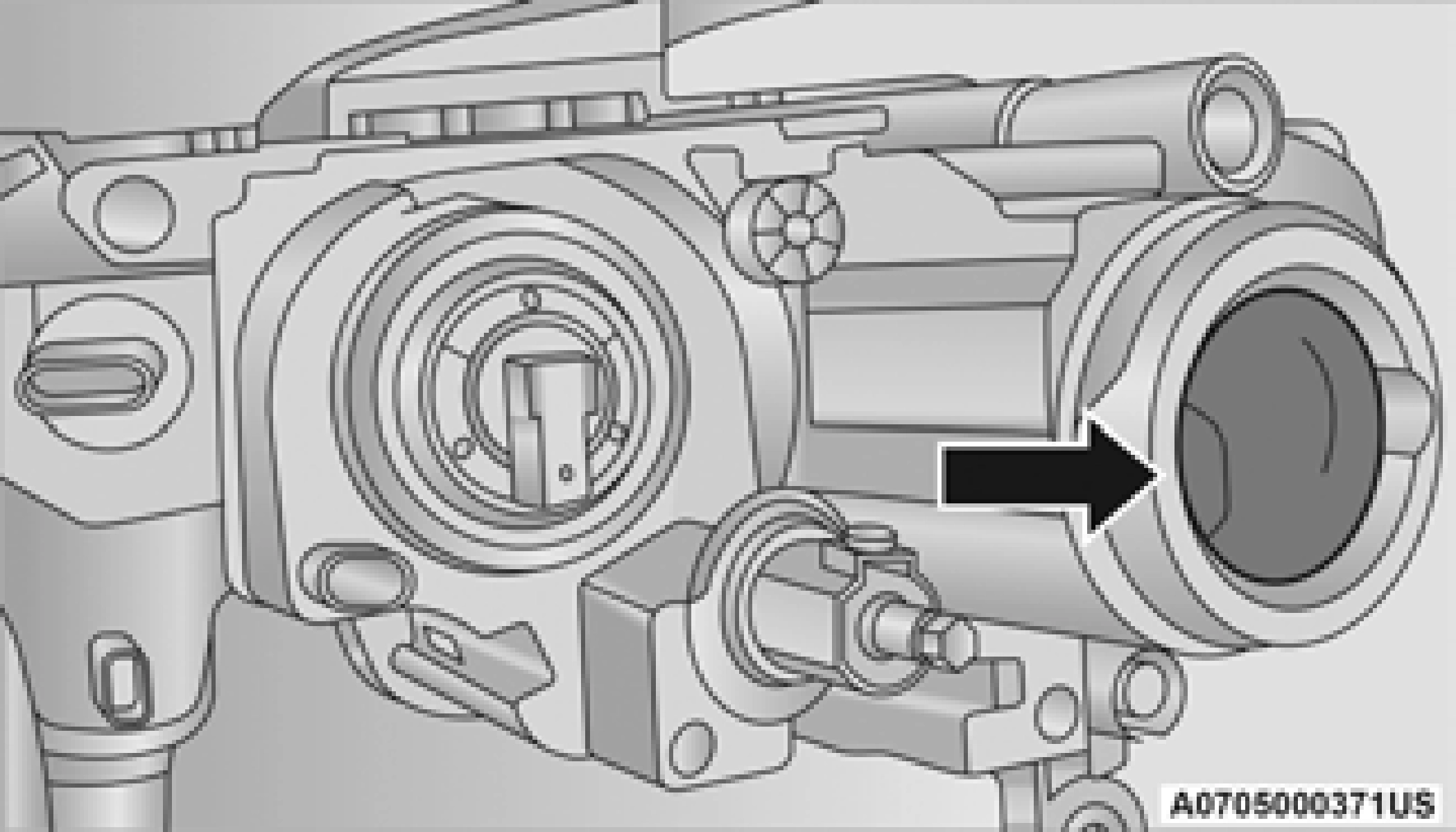 Rubber Boot Seal
NOTE:
On vehicles equipped with (HID) headlamps, when the headlamps are turned on, there is a blue hue to the lamps. This diminishes and becomes more white after approximately
10 seconds, as the system charges.
Ensure the rubber boot is properly reinstalled to prevent water and moisture from entering the lamp.
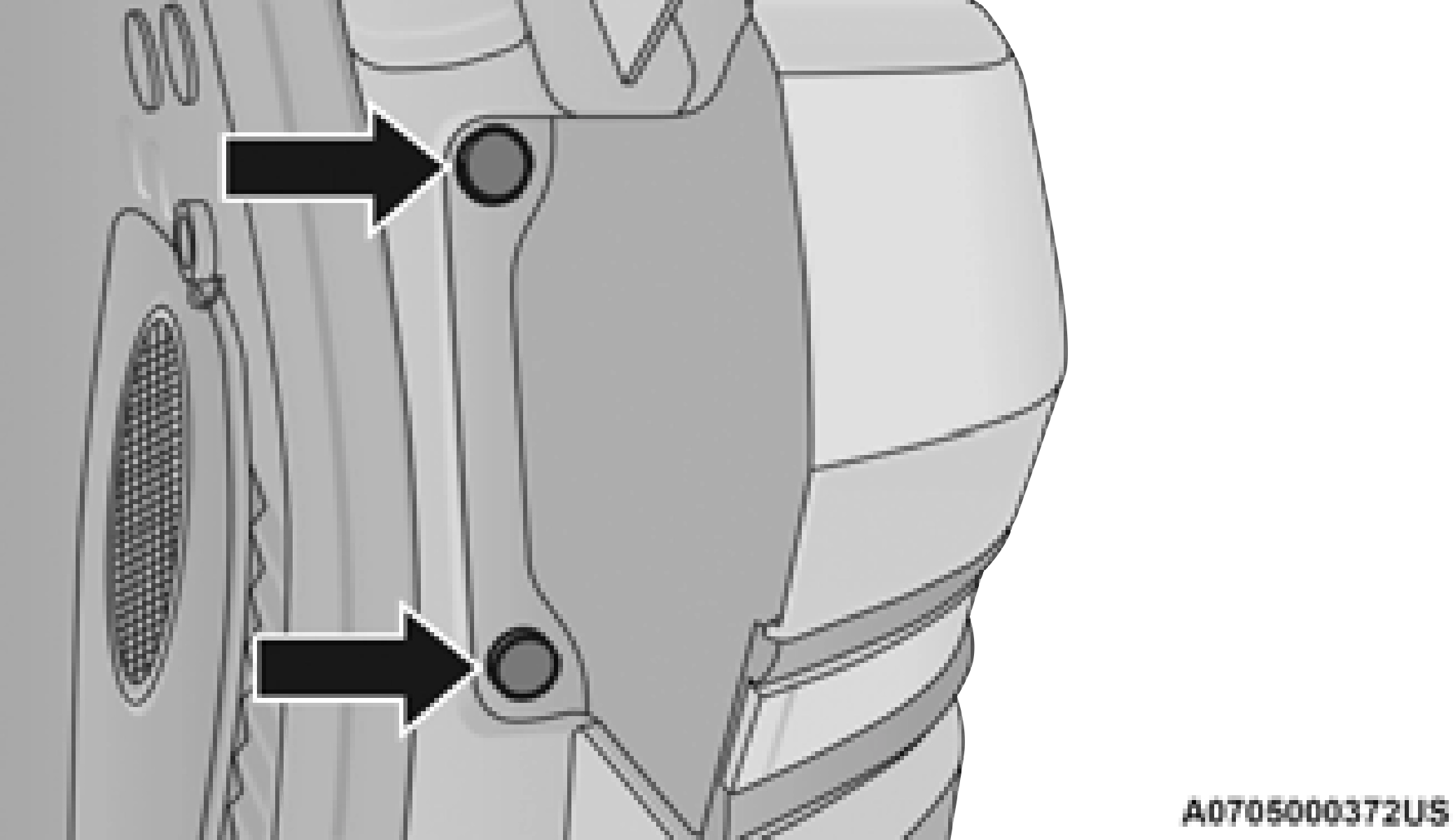
Front Turn Signal Lamp
Front Fog Lamps
Please see an authorized dealer for service on LED and Halogen front fog lamps.
Rear Tail, Stop, and Turn Signal Lamps See below steps to replace:
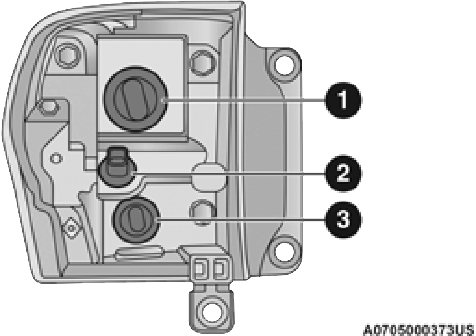
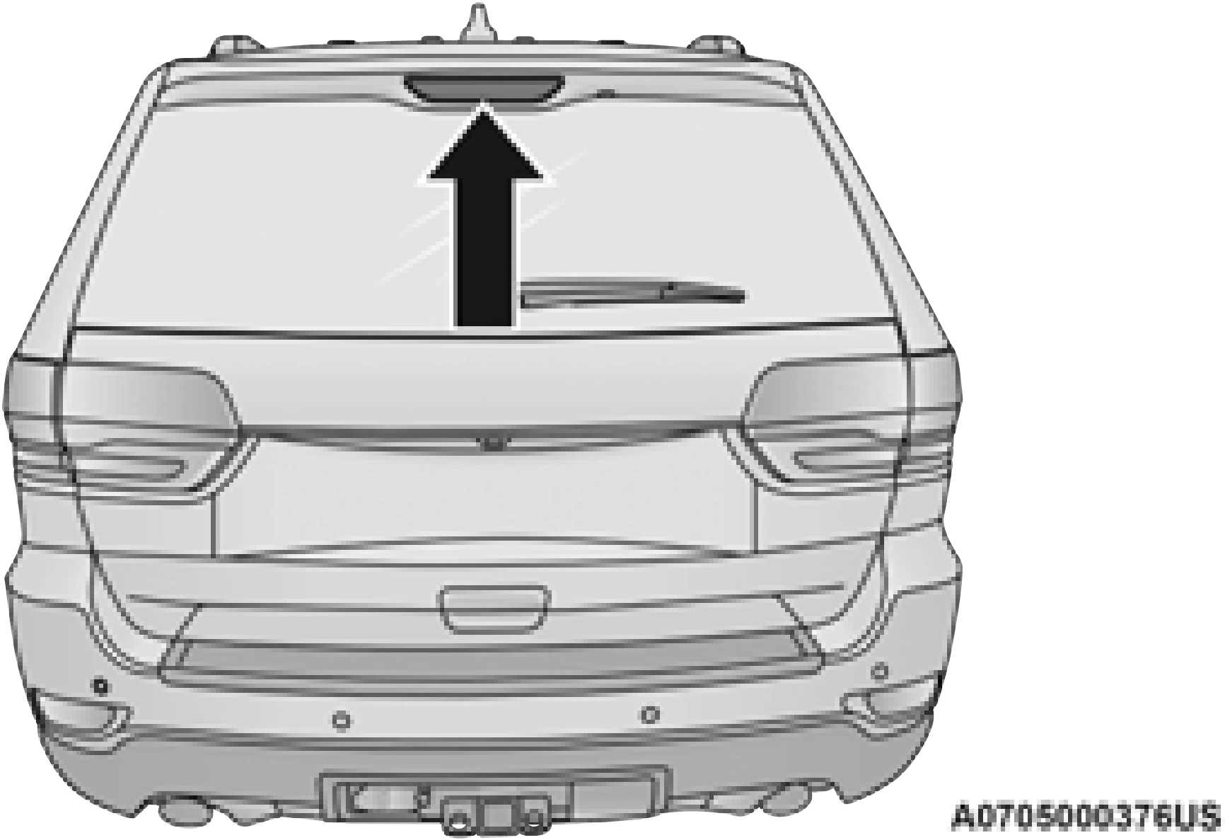
Rear Liftgate Mounted Tail Lamp
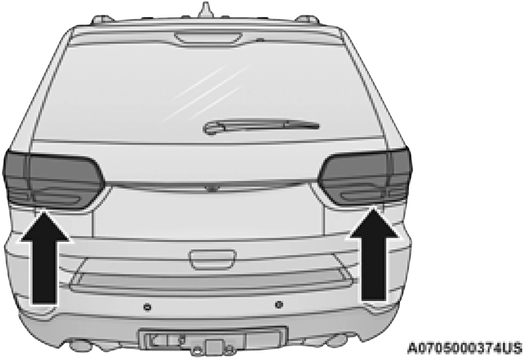
Rear Liftgate Tail Lamps
See below steps to replace:
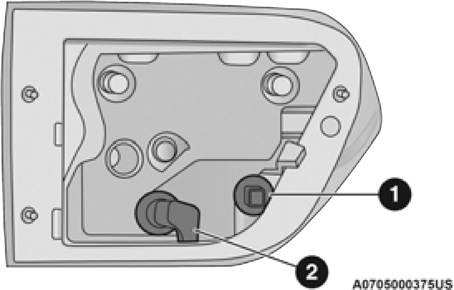
1 — Auxiliary LED Tail Connector — Do Not Remove 2 — Backup Bulb Socket
Center High Mounted Stop Lamp (CHMSL)
The (CHMSL) is an LED. Service at an authorized dealer.
Rear License Lamp
The rear license lamps are LEDs. See an authorized dealer for service.
Download Manual