DEALER SERVICE
An authorized dealer has the qualified service personnel, special tools, and equipment to perform all service opera- tions in an expert manner. Service Manuals are available which include detailed service information for your vehicle. Refer to these Service Manuals before attempting any proce- dure yourself.
NOTE:
Intentional tampering with emissions control systems may void your warranty and could result in civil penalties being assessed against you.
Refer to “Scheduled Servicing” in this section for the proper maintenance intervals.
NOTE:
Under no circumstances should oil change intervals exceed 10,000 miles (16,000 km), 12 months or 350 hours of engine run time, whichever comes first. The 350 hours of engine run or idle time is generally only a concern for fleet customers.
The oil change indicator system will remind you that it is time to take your vehicle in for scheduled maintenance. Refer to “Scheduled Servicing” for further information.
NOTE:
Under no circumstances should oil change intervals exceed 6,000 miles (10,000 km) or 6 months, whichever occurs first.
For best performance and maximum protection under all types of operating conditions, the manufacturer only recom- mends engine oils that are API Certified and meet the requirements of FCA Material Standard MS-6395.
For best performance and maximum protection under all types of operating conditions, the manufacturer only recom- mends full synthetic engine oils that meet the American Petroleum Institute (API) categories of SN.
The manufacturer recommends the use of Pennzoil Ultra 0W-40 engine or equivalent Mopar oil meeting the FCA Material Standard MS-12633 for use in all operating temperatures.
The engine oil fill cap also shows the recommended engine oil viscosity for your engine. For information on engine oil fill location, refer to “Engine Compartment” in this section for further information.
 This symbol means that the oil has been certified by the American Petroleum Institute (API). The manu- facturer only recommends API Certified engine oils.
This symbol certifies 0W-20, 5W-20, 0W-30, 5W-30 and 10W-30 engine oils.
Mopar SAE 0W-20 engine oil approved to FCA Material Standard MS-6395 such as Pennzoil, Shell Helix or equiva- lent is recommended for all operating temperatures. This engine oil improves low temperature starting and vehicle fuel economy.
The engine oil filler cap also shows the recommended engine oil viscosity for your engine. For information on engine oil filler cap location, refer to the “Engine Compartment” illus- tration in this section.
Lubricants which do not have both the engine oil certifica- tion mark and the correct SAE viscosity grade number should not be used.
Mopar SAE 5W-20 engine oil approved to FCA Material Standard MS-6395 such as Pennzoil, Shell Helix or equiva- lent is recommended for all operating temperatures. This engine oil improves low temperature starting and vehicle fuel economy.
The engine oil filler cap also shows the recommended engine oil viscosity for your engine. For information on engine oil filler cap location, refer to the “Engine Compartment” illus- tration in this section.
7
NOTE:
Vehicles equipped with a 5.7L engine must use SAE 5W-20 oil. Failure to do so may result in improper operation of the Fuel Saver Technology. Refer to “Fuel Saver Technology – If Equipped” in “Starting And Operating” for further information.
Lubricants which do not have both the engine oil certification mark and the correct SAE viscosity grade number should not be used.
Use Pennzoil Ultra Platinum 0W-40 engine or equivalent Mopar oil meeting the FCA Material Standard MS-12633 for use in all operating temperatures.
The engine oil filler cap also shows the recommended engine oil viscosity for your engine. For information on engine oil filler cap location, refer to “Engine Compartment” in this section for further information.
You may use synthetic engine oils provided the recom- mended oil quality requirements are met, and the recom- mended maintenance intervals for oil and filter changes are followed.
Synthetic engine oils which do not have both the engine oil certification mark and the correct SAE viscosity grade number should not be used.
The manufacturer strongly recommends against the addi- tion of any additives (other than leak detection dyes) to the engine oil. Engine oil is an engineered product and its perfor- mance may be impaired by supplemental additives.
Care should be taken in disposing of used engine oil and oil filters from your vehicle. Used oil and oil filters, indiscrimi- nately discarded, can present a problem to the environment. Contact an authorized dealer, service station or govern- mental agency for advice on how and where used oil and oil filters can be safely discarded in your area.
The engine oil filter should be replaced with a new filter at every engine oil change.
Engine Oil Filter Selection
This manufacturer's engines have a full-flow type disposable oil filter. Use a filter of this type for replacement. The quality of replacement filters varies considerably. Only high quality filters should be used to ensure most efficient service. Mopar engine oil filters are high quality oil filters and are recom- mended.
Refer to the “Maintenance Plan” in this section for the proper maintenance intervals.
NOTE:
Be sure to follow the “Severe Duty Conditions” maintenance interval if applicable.
Engine Air Cleaner Filter Selection
The quality of replacement engine air cleaner filters varies considerably. Only high quality filters should be used to
ensure most efficient service. Mopar engine air cleaner filters 7
are a high quality filter and are recommended.
Inspect engine air cleaner filter for dirt and/or debris, if you find evidence of either dirt or debris, change the air cleaner filter.
Engine Air Cleaner Filter Removal
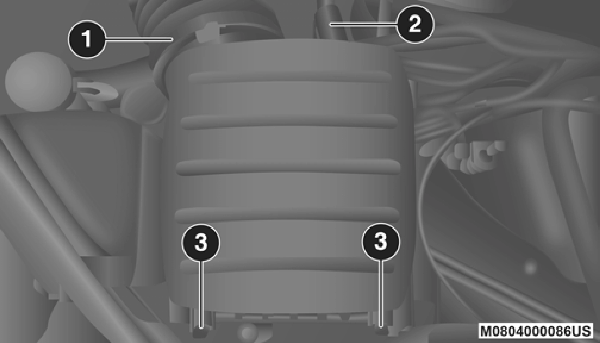
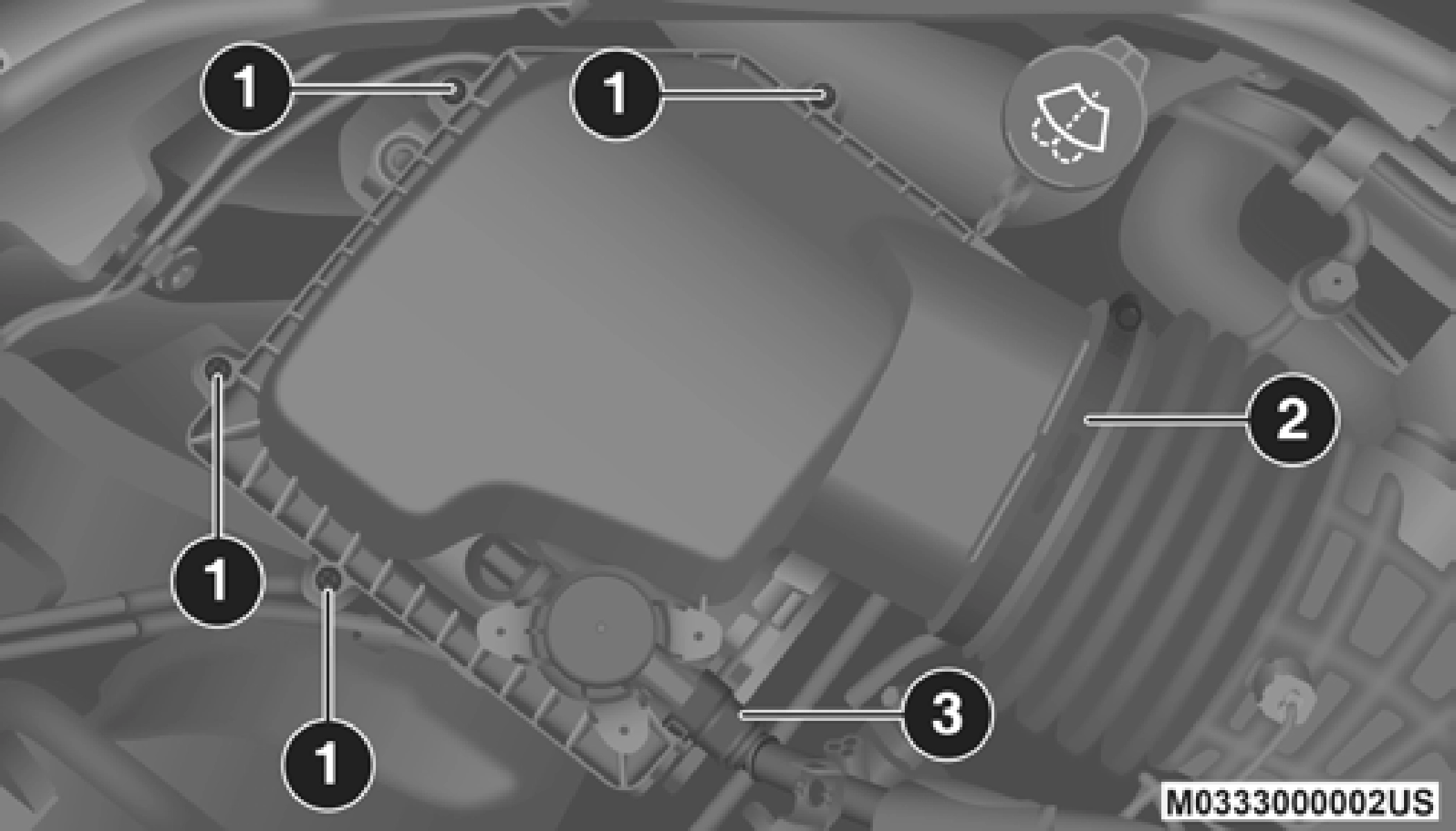
Air Cleaner Filter Cover
1 — Clean Air Hose Clamp 2 — Air Hose
3 — Spring Clips
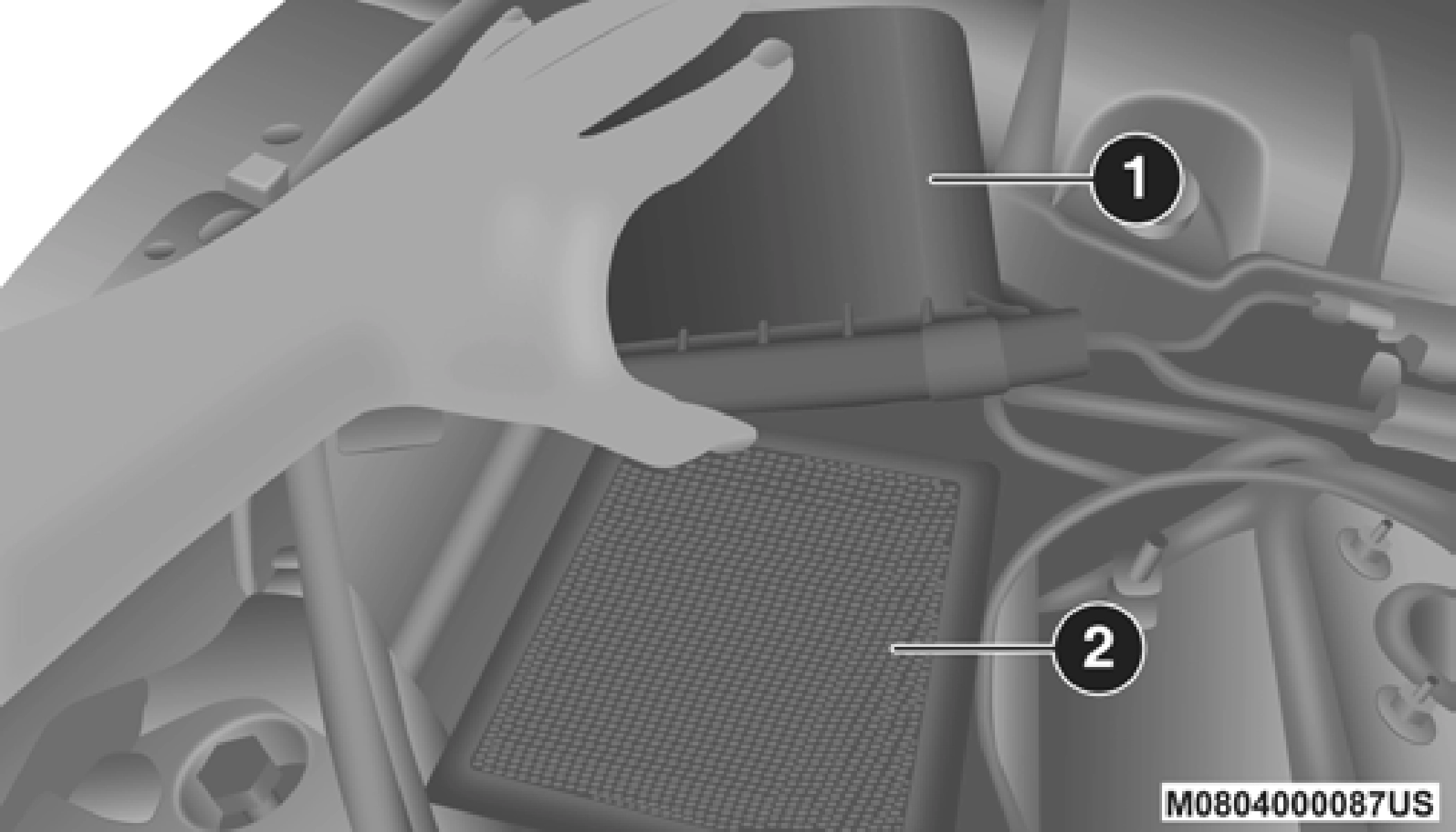
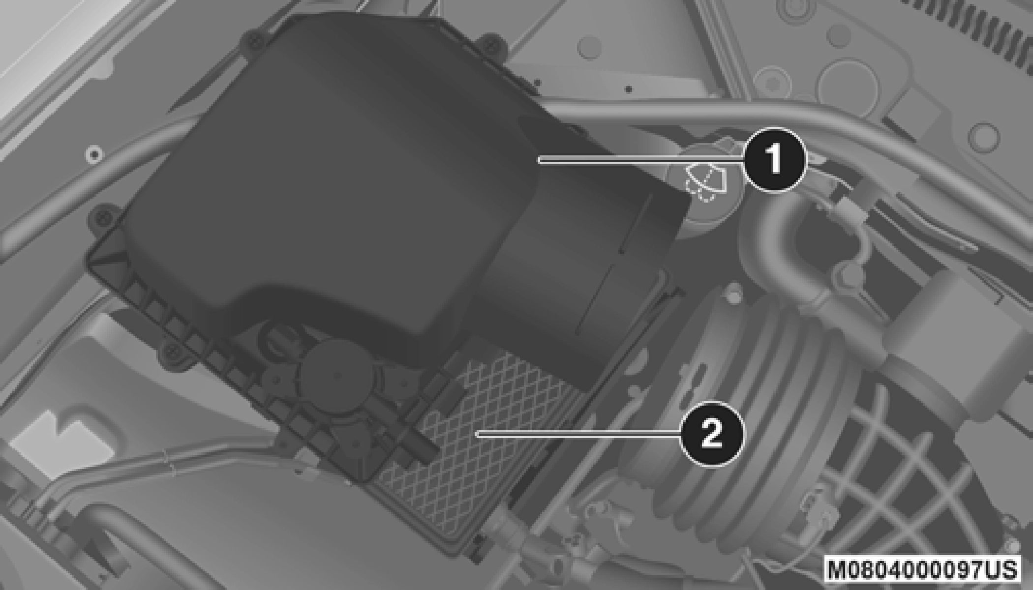
Open Air Cleaner Filter Assembly
1 — Air Cleaner Cover 2 — Air Cleaner Filter
 Air Cleaner Filter
Engine Air Cleaner Filter Installation NOTE:
Inspect and clean the housing if dirt or debris is present before replacing the air filter element.
7
Inspect engine air cleaner filter for dirt and or debris, if you find evidence of either dirt or debris, you should change your air cleaner filter.
Engine Air Cleaner Filter Removal
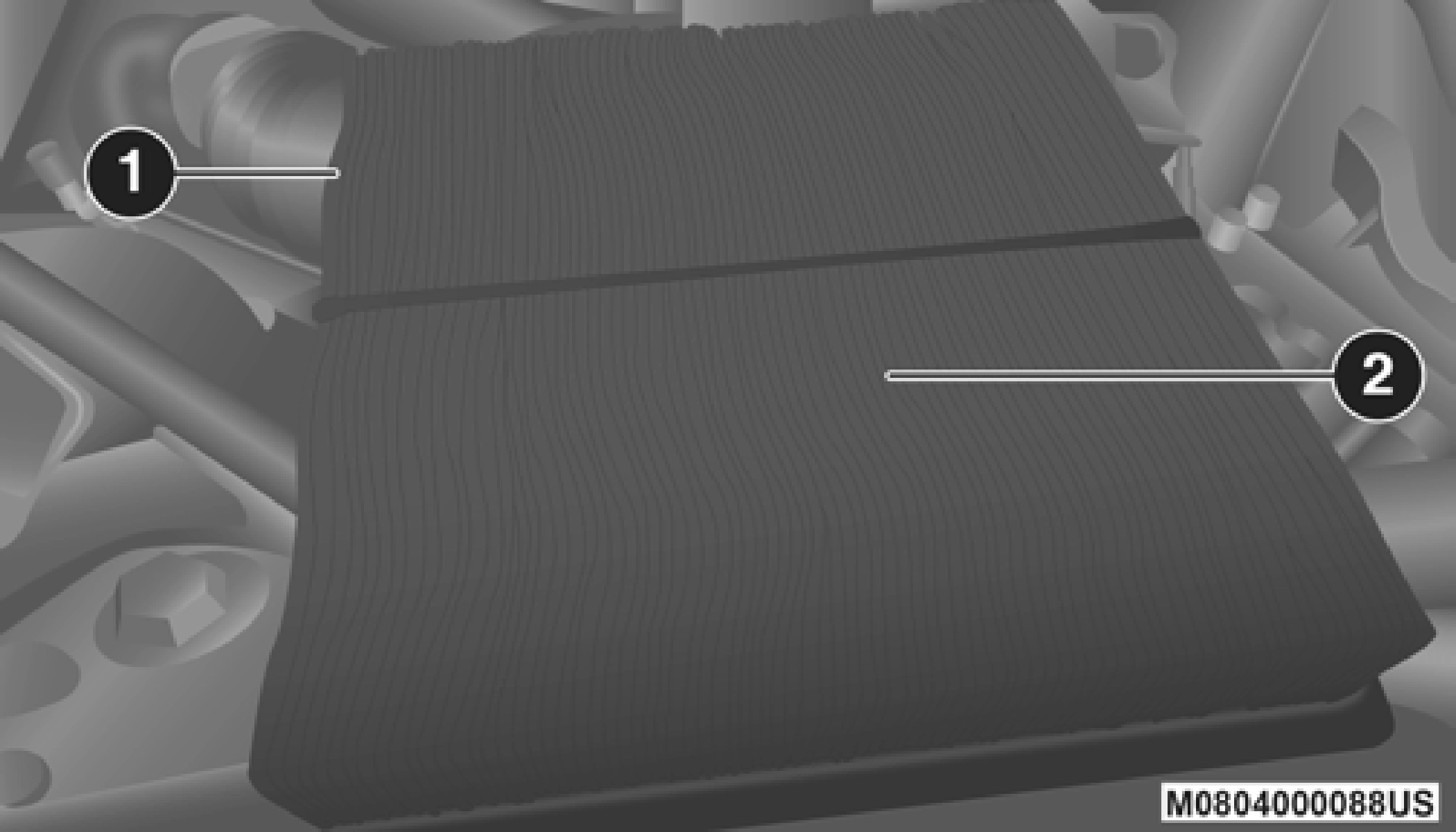
Open Air Cleaner Filter Assembly
1 — Air Cleaner Cover 2 — Air Cleaner Filter
 Air Cleaner Filter Assembly
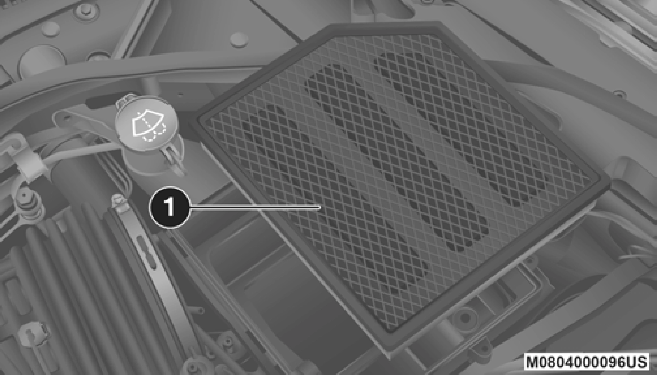
Air Cleaner Filter Removal
1 — Air Cleaner Filter
Engine Air Cleaner Filter Installation NOTE:
Inspect and clean the housing if dirt or debris is present before replacing the air filter element.
For best possible performance, the air conditioner should be checked and serviced by an authorized dealer at the start of each warm season. This service should include cleaning of the condenser fins and a performance test. Drive belt tension should also be checked at this time.
(Continued)
R-134a Air Conditioning Refrigerant is a hydrofluorocarbon (HFC) that is an ozone-friendly substance. The manufacturer recommends that air conditioning service be performed by an authorized dealer or other service facilities using recovery and recycling equipment.
NOTE:
Use only manufacturer approved A/C system Polyalkylene Glycol (PAG) compressor oil and refrigerants.
R–1234yf Air Conditioning Refrigerant is a hydrofluo- roolefin (HFO) that is endorsed by the Environmental Protection Agency and is an ozone-friendly substance with a low global-warming potential. The manufacturer recom- mends that air conditioning service be performed by an authorized dealer using recovery and recycling equipment.
NOTE:
Use only manufacturer approved A/C system PAG compressor oil, and refrigerants.
Refer to “Scheduled Servicing” in this section for the proper maintenance intervals.
The A/C air filter is located in the fresh air inlet behind the glove compartment. Perform the following procedure to replace the filter:
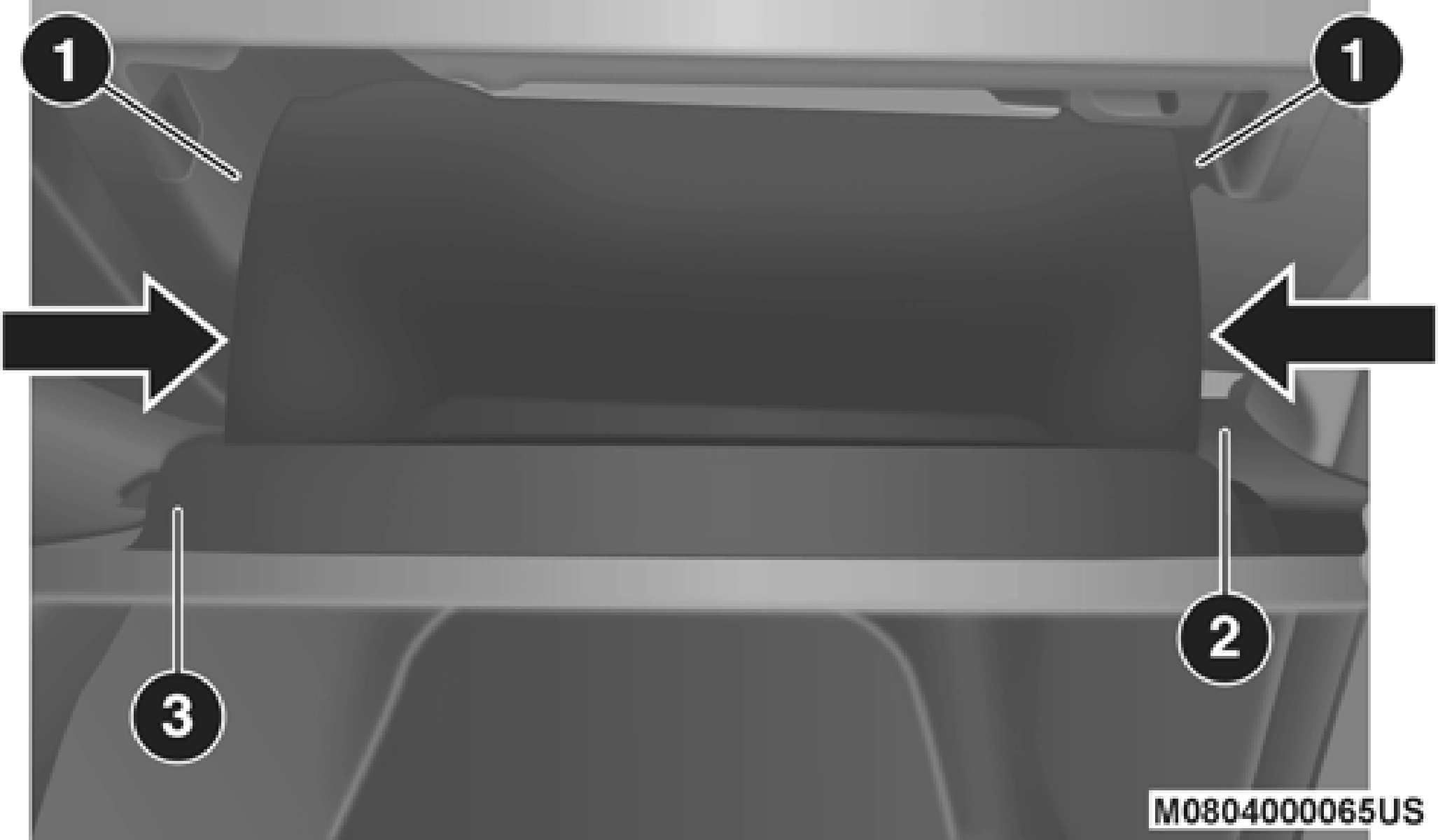
Glove Compartment
NOTE:
When disengaging the glove compartment door from its hinges, there will be some resistance.
7
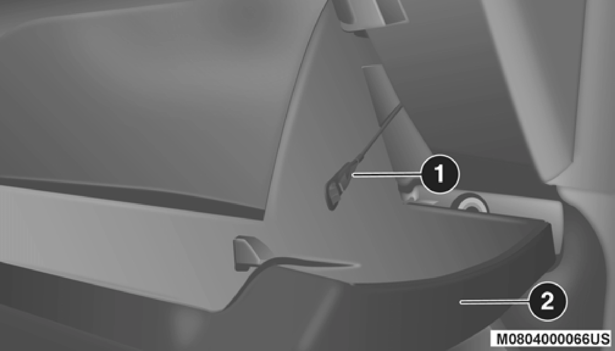 With the glove compartment door loose, remove the glove compartment tension tether and tether clip by sliding the clip toward the face of the glove compartment door and lifting the clip out of glove compartment door.
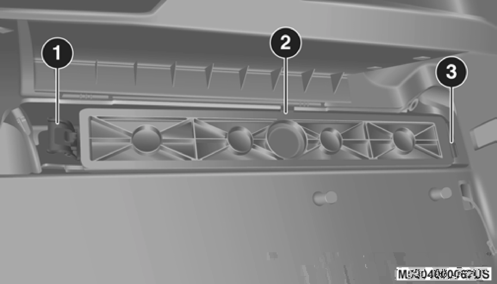 Right Side Of Glove Compartment
A/C Air Filter Cover
NOTE:
Ensure the glove compartment door hinges and glove compartment travel stops are fully engaged.
7
When inspecting accessory drive belts, small cracks that run across ribbed surface of belt from rib to rib, are considered normal. These are not a reason to replace belt. However, cracks running along a rib (not across) are not normal. Any belt with cracks running along a rib must be replaced. Also have the belt replaced if it has excessive wear, frayed cords or severe glazing.
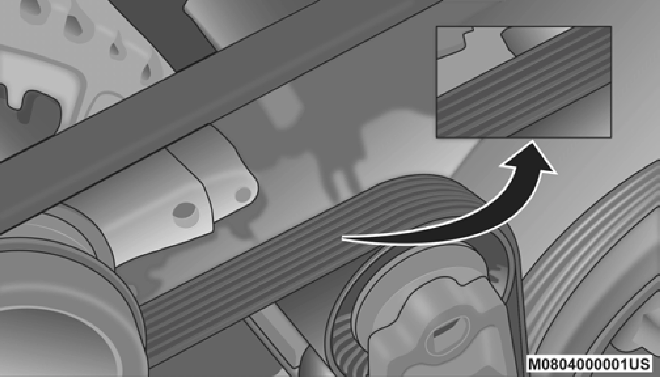
Accessory Belt (Serpentine Belt)
Conditions that would require replacement:
Some conditions can be caused by a faulty component such as a belt pulley. Belt pulleys should be carefully inspected for damage and proper alignment.
Belt replacement on some models requires the use of special tools, we recommend having your vehicle serviced at an authorized dealer.
Locks and all body pivot points, including such items as seat tracks, door hinge pivot points and rollers, liftgate, tailgate, decklid, sliding doors and hood hinges, should be lubricated periodically with a lithium based grease, such as Mopar Spray White Lube to ensure quiet, easy operation and to protect against rust and wear. Prior to the application of any lubricant, the parts concerned should be wiped clean to
remove dust and grit; after lubricating, excess oil and grease should be removed. Particular attention should also be given to hood latching components to ensure proper function. When performing other underhood services, the hood latch, release mechanism and safety catch should be cleaned and lubricated.
The external lock cylinders should be lubricated twice a year, preferably in the Fall and Spring. Apply a small amount of a high quality lubricant, such as Mopar Lock Cylinder Lubri- cant directly into the lock cylinder.
Clean the rubber edges of the wiper blades and the wind- shield periodically with a sponge or soft cloth and a mild nonabrasive cleaner. This will remove accumulations of salt or road film.
Operation of the wipers on dry glass for long periods may cause deterioration of the wiper blades. Always use washer fluid when using the wipers to remove salt or dirt from a dry windshield.
Avoid using the wiper blades to remove frost or ice from the windshield. Keep the blade rubber out of contact with petro- leum products such as engine oil, gasoline, etc.
NOTE:
Life expectancy of wiper blades varies depending on geographical area and frequency of use. Poor performance of blades may be present with chattering, marks, water lines or wet spots. If any of these conditions are present, clean the wiper blades or replace as necessary.
The wiper blades and wiper arms should be inspected peri- odically, not just when wiper performance problems are experienced. This inspection should include the following points:
If a wiper blade or wiper arm is damaged, replace the affected wiper arm or blade with a new unit. Do not attempt to repair a wiper arm or blade that is damaged.
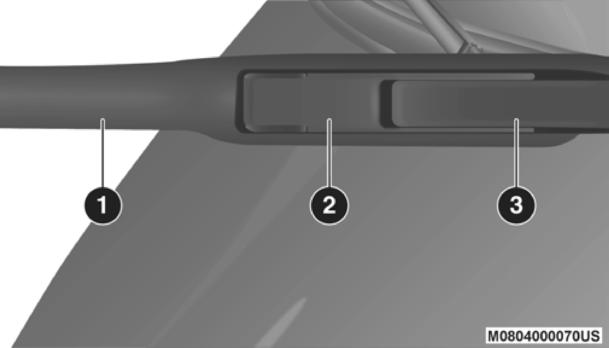
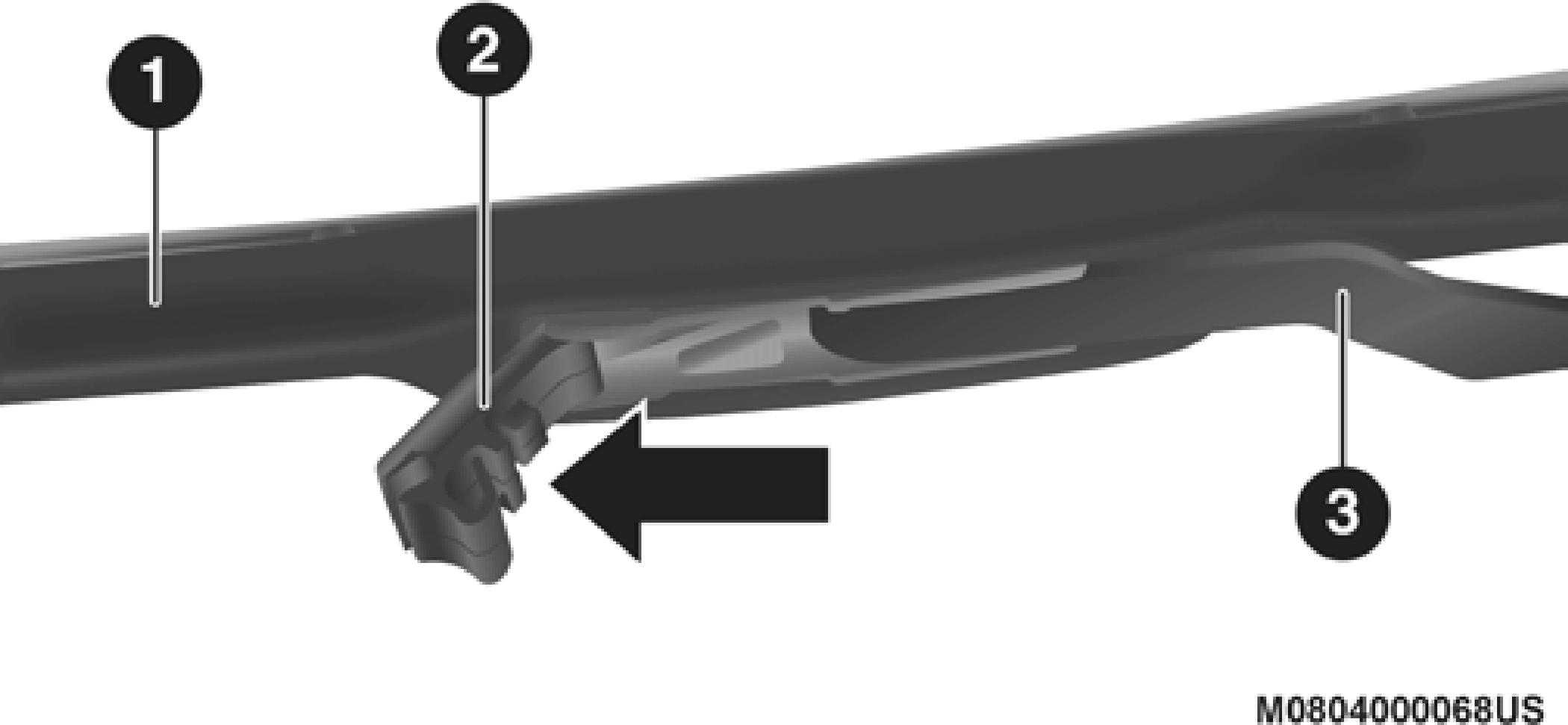
Wiper Blade With Release Tab In Locked Position
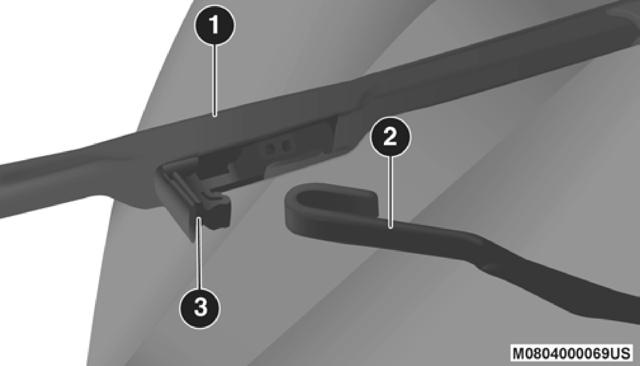
Wiper Blade With Release Tab In Unlocked Position
1 — Wiper Blade 2 — Release Tab
 7
7
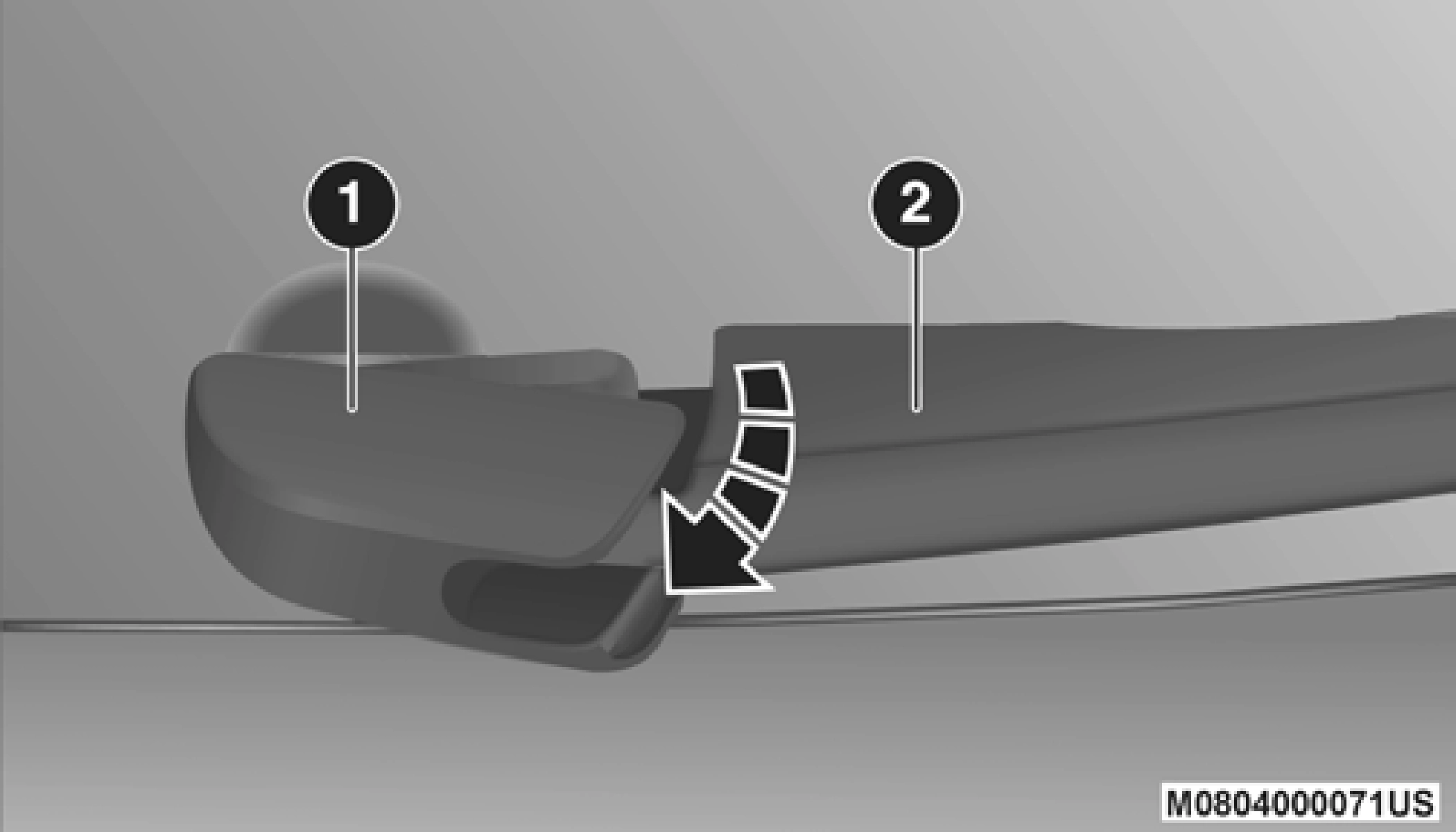
Wiper Blade Removed From Wiper Arm
3 — Wiper Arm 1 — Wiper Blade
2 — Wiper Arm 3 — Release Tab
Installing The Front Wipers
NOTE:
The rear wiper arm cannot be fully raised off the glass unless the wiper arm pivot cap is unsnapped first. Attempting to fully raise the rear wiper arm without unsnapping the wiper arm pivot cap may damage the vehicle.
Wiper Pivot Cap In Unlocked Position
1 — Wiper Arm Pivot Cap 2 — Wiper Arm
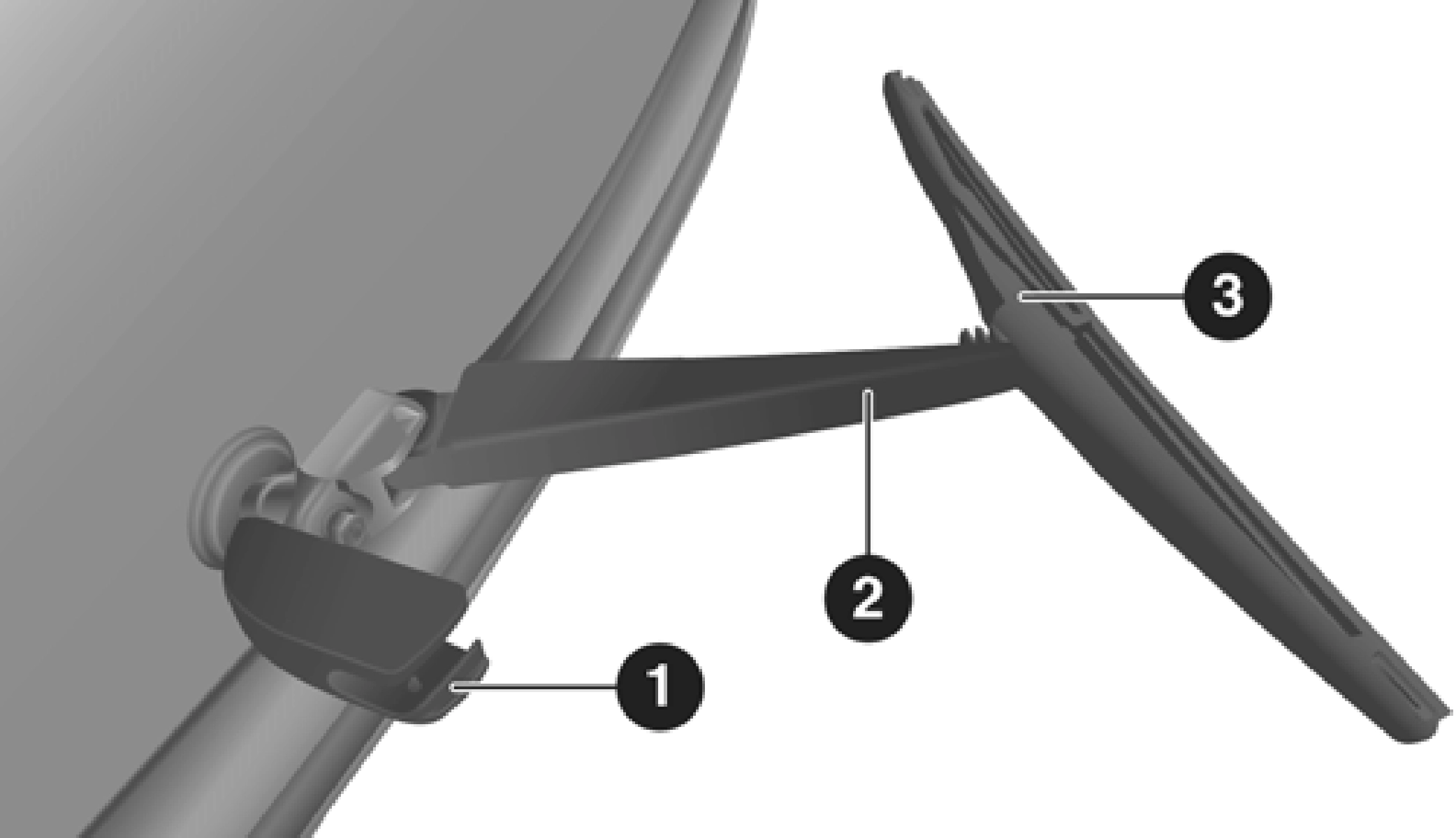
Wiper Blade In Folded Out Position
1 — Wiper Arm Pivot Cap 2 — Wiper Arm
3 — Wiper Blade
NOTE:
Resistance will be accompanied by an audible snap.
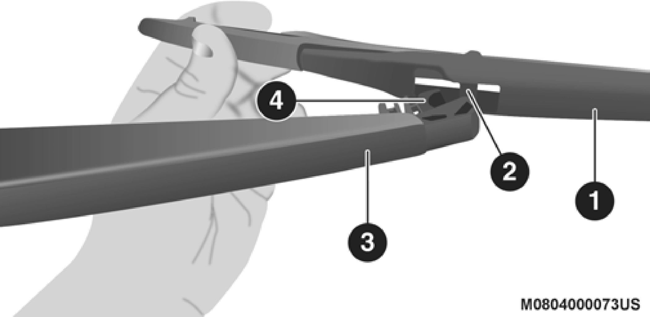 Still grasping the bottom end of the wiper blade, move the wiper blade upward and away from the wiper arm to disengage.
7
Wiper Blade Removed From Wiper Arm
4 — Wiper Arm Receptacle
Installing The Rear Wiper
NOTE:
The rear wiper arm cannot be fully raised off the glass unless the wiper arm pivot cap is unsnapped first. Attempting to fully raise the rear wiper arm without unsnapping the wiper arm pivot cap may damage the vehicle.
The best protection against carbon monoxide entry into the vehicle body is a properly maintained engine exhaust system.
If you notice a change in the sound of the exhaust system; or if the exhaust fumes can be detected inside the vehicle; or when the underside or rear of the vehicle is damaged; have an authorized technician inspect the complete exhaust system and adjacent body areas for broken, damaged, dete- riorated, or mispositioned parts. Open seams or loose connections could permit exhaust fumes to seep into the passenger compartment. In addition, have the exhaust system inspected each time the vehicle is raised for lubrica- tion or oil change. Replace as required.
(Continued)
Under normal operating conditions, the catalytic converter will not require maintenance. However, it is important to keep the engine properly tuned to ensure proper catalyst operation and prevent possible catalyst damage.
NOTE:
Intentional tampering with emissions control systems can result in civil penalties being assessed against you.
In unusual situations involving grossly malfunctioning engine operation, a scorching odor may suggest severe and abnormal catalyst overheating. If this occurs, stop the vehicle, turn off the engine and allow it to cool. Service, including a tune-up to manufacturer's specifications, should be obtained immediately.
To minimize the possibility of catalytic converter damage: 7
Check the engine coolant (antifreeze) protection every 12 months (before the onset of freezing weather, where applicable). If the engine coolant (antifreeze) is dirty, the system should be drained, flushed, and refilled with fresh OAT coolant (conforming to MS.90032) by an authorized
dealer. Check the front of the A/C condenser for any accu- mulation of bugs, leaves, etc. If dirty, clean by gently spraying water from a garden hose vertically down the face of the condenser.
Check the engine cooling system hoses for brittle rubber, cracking, tears, cuts, and tightness of the connection at the coolant recovery bottle and radiator. Inspect the entire system for leaks. DO NOT REMOVE THE COOLANT PRES- SURE CAP WHEN THE COOLING SYSTEM IS HOT.
NOTE:
Some vehicles require special tools to add coolant properly. Failure to fill these systems properly could lead to severe internal engine damage. If any coolant is needed to be added to the system please contact an authorized dealer.
If the engine coolant (antifreeze) is dirty or contains visible sediment, have an authorized dealer clean and flush with OAT coolant (antifreeze) (conforming to MS.90032).
Refer to the “Maintenance Plan” in this section for the proper maintenance intervals.
Refer to “Fluids And Lubricants” in “Technical Specifica- tions” for further information.
NOTE:
Your vehicle has been built with an improved engine coolant (OAT coolant conforming to MS.90032) that allows extended maintenance intervals. This engine coolant (antifreeze) can
be used up to 10 years or 150,000 miles (240,000 km) before 7
replacement. To prevent reducing this extended mainte- nance period, it is important that you use the same engine coolant (OAT coolant conforming to MS.90032) throughout the life of your vehicle.
Please review these recommendations for using Organic Additive Technology (OAT) engine coolant (antifreeze) that meets the requirements of FCA Material Standard MS.90032. When adding engine coolant (antifreeze):
NOTE:
The cap must be fully tightened to prevent loss of engine coolant (antifreeze), and to ensure that engine coolant (anti- freeze) will return to the radiator from the coolant expansion bottle/recovery tank if so equipped.
The cap should be inspected and cleaned if there is any accu- mulation of foreign material on the sealing surfaces.
Used ethylene glycol-based coolant (antifreeze) is a regu- lated substance requiring proper disposal. Check with your local authorities to determine the disposal rules for your community. To prevent ingestion by animals or children, do not store ethylene glycol-based coolant in open containers or allow it to remain in puddles on the ground. If ingested by a child or pet, seek emergency assistance immediately. Clean up any ground spills immediately.
The coolant bottle provides a quick visual method for deter- mining that the coolant level is adequate. With the engine OFF and cold, the level of the engine coolant (antifreeze) in the bottle should be between the ranges indicated on the bottle.
The radiator normally remains completely full, so there is no need to remove the radiator/coolant pressure cap unless checking for engine coolant (antifreeze) freeze point or replacing coolant. Advise your service attendant of this. As long as the engine operating temperature is satisfactory, the coolant bottle need only be checked once a month.
When additional engine coolant (antifreeze) is needed to maintain the proper level, only OAT coolant that meets the 7
requirements of FCA Material Standard MS.90032 should be added to the coolant bottle. Do not overfill.
NOTE:
When the vehicle is stopped after a few miles/kilometers of operation, you may observe vapor coming from the front of the engine compartment. This is normally a result of mois- ture from rain, snow, or high humidity accumulating on the radiator and being vaporized when the thermostat opens, allowing hot engine coolant (antifreeze) to enter the radiator.
If an examination of your engine compartment shows no evidence of radiator or hose leaks, the vehicle may be safely driven. The vapor will soon dissipate.
In order to ensure brake system performance, all brake system components should be inspected periodically. Refer to the “Maintenance Plan” in this section for the proper maintenance intervals.
The fluid level of the master cylinder should be checked when- ever the vehicle is serviced, or immediately if the brake system warning light is on. If necessary, add fluid to bring level within the designated marks on the side of the reservoir of the brake master cylinder. Be sure to clean the top of the master cylinder area before removing cap. With disc brakes, fluid level can be expected to fall as the brake pads wear. Brake fluid level should be checked when pads are replaced. If the brake fluid is abnor- mally low, check the system for leaks.
Refer to “Fluids And Lubricants” in “Technical Specifica- tions” for further information.
WARNING!
reservoir cap secured at all times. Brake fluid in a open 7
container absorbs moisture from the air resulting in a
lower boiling point. This may cause it to boil unexpect- edly during hard or prolonged braking, resulting in sudden brake failure. This could result in a collision.
(Continued)
It is important to use the proper transmission fluid to ensure optimum transmission performance and life. Use only the manufacturer's specified transmission fluid. Refer to “Fluids And Lubricants” in “Technical Specifications” for fluid spec- ifications. It is important to maintain the transmission fluid at the correct level using the recommended fluid.
NOTE:
No chemical flushes should be used in any transmission; only the approved lubricant should be used.
The manufacturer strongly recommends against using any special additives in the transmission. Automatic Transmis- sion Fluid (ATF) is an engineered product and its perfor- mance may be impaired by supplemental additives. Therefore, do not add any fluid additives to the transmis- sion. Avoid using transmission sealers as they may adversely affect seals.
The fluid level is preset at the factory and does not require adjustment under normal operating conditions. Routine fluid level checks are not required; therefore the transmis- sion has no dipstick. An authorized dealer can check the transmission fluid level using special service tools. If you notice fluid leakage or transmission malfunction, visit an authorized dealer immediately to have the transmission fluid level checked. Operating the vehicle with an improper fluid level can cause severe transmission damage.
Under normal operating conditions, the fluid installed at the factory will provide satisfactory lubrication for the life of the vehicle.
Routine fluid and filter changes are not required. However, change the fluid and filter if the fluid becomes contaminated (with water, etc.), or if the transmission is disassembled for any reason.
For normal service, periodic fluid level checks are not required. When the vehicle is serviced for other reasons the exterior surfaces of the axle assembly should be inspected. If gear oil leakage is suspected inspect the fluid level. Refer to “Fluids And Lubricants” in “Technical Specifications” for further information.
The front axle oil level needs to be no lower than 1/8 inch 7
(3 mm) below the bottom of the fill hole.
The front axle fill and drain plugs should be tightened to 22 to 29 ft lbs (30 to 40 N·m).
The rear axle oil level needs to be no lower than 1/8 inch (3 mm) below the bottom of the fill hole.
The rear axle fill and drain plugs should be tightened to 22 to 29 ft lbs (30 to 40 N·m).
Use only the manufacturer's recommended fluid. Refer to “Fluids And Lubricants” in “Technical Specifications” for further information.
For normal service, periodic fluid level checks are not required. When the vehicle is serviced for other reasons the exterior surfaces of the transfer case assembly should be inspected. If oil leakage is suspected inspect the fluid level. Refer to “Fluids And Lubricants” in “Technical Specifica- tions” for further information.
While the vehicle is in a level position, add fluid at the filler hole until it runs out of the hole.
First remove fill plug, then remove drain plug. Recom- mended tightening torque for drain and fill plugs is 15 to 25 ft lbs (20 to 34 N·m).
Use only the manufacturer's recommended fluid. Refer to “Fluids And Lubricants” in “Technical Specifications” for further information.
Download Manual