Towing
|
the WARNING: Do not exceed GVWR or the GAWR specified on the certification label. bey WARNING: Towing trailers ond the maximum recommended gross trailer weight exceeds the limit of your vehicle and could result in engine damage, transmission damage, structural damage, loss of vehicle control, vehicle rollover and personal injury. the l WARNING: Do not exceed owest rating capacity for your vehicle or trailer hitch. Overloading your vehicle or trailer hitch can impair your vehicle stability and handling. Failure to follow this instruction could result in the loss of control of your vehicle, personal injury or death. drill, WARNING: Do not cut, weld or modify the trailer hitch. Modifying the trailer hitch could reduce the hitch rating. |
 Your vehicle may have electrical items, such as fuses or relays, related to towing. See Fuse Specification Chart (page 339).
Your vehicle may have ability to modify trailer towing features. See General Information (page 110).
Towing a trailer places an extra load on your vehicle's engine, transmission, axle, brakes, tires and suspension. Inspect these components periodically during, and after, any towing operation.
Note: To prevent your trailer from accumulating distance, and the trailer information status appearing when you restart your vehicle after disconnecting your trailer, you must deactivate your trailer. Using the information display, go to the Towing menu and then the Select Trailer option. Select the No active trailer option. See General Information (page 110).
Load Placement
To help minimize how trailer movement affects your vehicle when driving:
• Load the heaviest items closest to the trailer floor.
• Load the heaviest items centered between the
left-hand and right-hand side trailer tires.
282
vehicle, when viewed from the side.
When driving with a trailer or payload, a slight takeoff vibration or shudder may be present due to the increased payload weight.
Additional information regarding proper trailer loading and setting your vehicle up for towing is in another chapter of this manual. See Recommended Towing Weights (page 300).
You can also find information in the RV & Trailer Towing Guide available at your authorized dealer, or online.
|
RV & Trailer Towing Guide Online |
|
|
Website |
h t tp: / / ww w .f l ee t. f o r d . c om / t o wing- g uid e s/ |
TRAILER REVERSING AIDS (IF EQUIPPED)


283
This feature helps you to steer your vehicle when reversing with a trailer by:
Each trailer you use with your vehicle has to be setup once.
You must take care to follow the setup process accurately to correctly place the sticker or sensor.
Contact your dealership if you need assistance setting up your trailer.
Note: Your vehicle saves the trailer information when you enter it into the system. You can add a maximum of 10 trailers to the system.
Note: The system is not a substitute for safe driving practices.
Note: You must always be aware of your vehicle and trailer combination, and the surrounding environment.
Note: The system does not detect or prevent your vehicle or trailer from making contact with obstacles in the surrounding environment.
Note: Keep in mind that the front end of your vehicle swings out when changing the direction of the trailer.
Note: The system relies on user measurements to determine sticker placement or user installation of a sensor to determine system limits. It is critical to correctly take the key measurements or properly install the sensor. Incorrect measurements or sensor placement can result in the improper function of the system up to and including contact between your vehicle and trailer. Even with correct measurements and sensor placement, the system cannot determine if the trailer body may contact your vehicle. Check the clearance between your vehicle and trailer, especially for sharp turns.
Note: The system limits vehicle speed when backing up. The system is not a replacement for proper use of the throttle and brake pedals.
Note: The system does not support backing up when towing multiple trailers. If you are towing more than one trailer, you must disconnect the additional trailers before using the system.
Hitch your trailer to your vehicle and connect the electrical wiring harness. Check to make sure that the wiring is working. See Essential Towing Checks (page 305).
E209759
Park your vehicle and hitched trailer on a level surface.
284
For best results, make sure that your trailer rides level with the ground when you hitch your vehicle. More information on selecting your towbar is available in the Towing section. See Towing (page 282).
E209760
Make sure that the trailer and your vehicle are in line with each other. You can do this by putting the transmission in drive (D) and pulling straight forward.
Note: Select Default Electric/Surge/None if your trailer has electric, surge or no brakes.
Note: The default option is Low. We recommend this for most trailers. If the trailer brakes require more initial voltage, or if you prefer more aggressive braking, select Medium or High.
Note: The system may prompt you to setup Trailer Blind Spot before continuing the setup process.
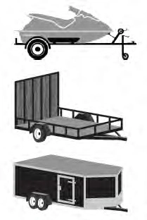
Conventional Trailer Setup (If Equipped)
The following are examples of conventional trailers.
285
 E311876
You must place the sticker in an area visible by the rear view camera.
Note: The cargo and trailer hookup lamps turn on to improve visibility.
Note: An assistant can help to carry out the following procedure.
Note: Make sure nothing can obstruct the rear view camera's view of the sticker. For example, items such as a jack handle or wiring.
Note: Position the sticker on a flat, dry and clean horizontal surface. For best results, apply the sticker when temperatures are above 32°F (0°C).
Note: Do not move stickers after placing them. Do not re-use any stickers if removed.
Note: You can purchase additional stickers through your authorized dealer.
E310619
Use the supplied measurement card, a tape measure and pen to carefully mark the area to attach the sticker. The sticker is in the back cover pocket of your quick start guide. Make sure the entire sticker is within the green zone between the two arcs or distance markers on the diagram, and is also visible in the rear view camera display.
Once you have found the correct location, place the sticker.
After you place the sticker on your trailer, you must take some measurements.
Note: You must take accurate measurements for the system to properly operate.
Note: When rounding in inches, round upward if the measured length is a quarter inch or greater. Round downward if the measured length is less than a quarter inch. For example, 12.25 in (31.11 cm) would be rounded up to 12.50 in (31.75 cm). 12.13 in (30.8 cm) would be rounded down to 12.00 in (30.48 cm).
Note: When rounding in centimeters, round to the nearest whole centimeter. If the measurement is less than 0.2 in (0.5 cm) round downward. If the measurement is more than or equal to 0.2 in (0.5 cm) round upward. For example, 11.9 in (30.3 cm) would be rounded down to 11.8 in (30 cm).
12.0 in (30.5 cm) would be rounded up to
12.2 in (31 cm).
286
Note: Use consistent metric or imperial units as required by your country or vehicle.
The measurement card requires you to record four key distances: A, B, C and D. Record the trailer name for these measurements.
Follow the on-screen prompts to enter each of the measurements. Use the up and down arrows to increase or decrease the numbers, as necessary. Press OK to confirm each measurement. When you add the last measurement, the information display shows all the measurements you entered. You can choose to confirm or change the measurements.
Check the rear view camera display to see if the system identifies the sticker. The system marks the sticker with a red circle. Confirm that the red circle shows over the sticker image in the rear view camera display.
Note: If the system cannot locate the sticker, try cleaning the camera lens. Make sure the sticker is within the zone indicated in Placing the Sticker.
To complete setup, drive your vehicle straight forward between 4–24 mph (6–39 km/h), as directed by the information display.
The information display shows a message during calibration and after calibration is complete
Note: Calibration steps for conventional trailers, fifth wheel and gooseneck trailers vary. Calibration instructions for fifth wheel
Note: Round distance D to the nearest inch.
Note: Distance D is the center of the axles for trailers with more than one axle.
and gooseneck trailers are in the following
section.
Note: Keep the steering wheel straight during the calibration process. If the steering wheel is in a turned position, the calibration pauses.
Note: For best results, do not calibrate the system at night.
287
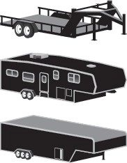
Fifth Wheel and Gooseneck Trailer Setup (If Equipped)
The following are examples of fifth wheel and gooseneck trailers.
 E311877
To use the system with a fifth wheel or gooseneck trailer, you must install a sensor. Refer to the instructions in the sensor kit for proper installation.
Note: Make sure the arrows on the sensor housing are facing up. Mount the sensor to a vertical part of the trailer that pivots and moves when you turn your vehicle. Do not mount to a stationary surface or to the truck side of the fifth wheel trailer hitch.
Note: You need to replace the 7/4 way connector in the bumper with the recommended 7/12 pin connector if your vehicle did not come with the fifth wheel prep package. See your authorized dealer.
Note: If your vehicle has the fifth wheel prep package, you have everything you need. If your vehicle does not have the fifth wheel prep package, see your authorized dealer to purchase the sensor kit and the 7/12 pin connector.
During calibration, the system determines the trailer length. The system supports trailer lengths of 10–39 ft (3–11.94 m) distance from the hitch point to the center of the axle or axles.
To calibrate the system, you need an area where you can safely drive forward and turn left or right. An open parking lot is an ideal place to perform the calibration.
288
Drive straight at approximately 5 mph (8 km/h) to align the trailer behind your
vehicle. The information display and center screen provide you with instructions and tells you when the system is ready for a turn. Turn left or right whenever you are ready and in a safe turning area.
Note: You need to turn approximately 90 degrees to calibrate the system.
Note: The information display shows if you are going too slow or fast. Calibration pauses if the speed is outside the required range of 2–16 mph (4–25 km/h).
To use the system, press the button and watch the information display. Use the controls on the steering wheel to highlight the trailer, then press OK to select the trailer.
When the system locates the sticker or confirms the sensor is connected, the display prompts you to shift into reverse (R). The system turns on.
Note: If you use the steering wheel, the system turns off and a warning appears in the information display.
Follow the screen prompts to steer your vehicle and trailer.
Note: You may have to drive forward to straighten the trailer.
Take your hands off the steering wheel and turn the control knob instead. The knob acts as the steering control for the trailer.
Note: The more you turn the knob, the sharper the trailer turns.
289
E209812 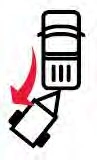
Turn and hold counterclockwise to make the trailer go left.
E209813 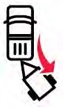
Turn and hold clockwise to make the trailer go right.
Note: Practice maneuvering with the system in a safe open area first.
Note: Try backing up in a straight line and then turning the knob slowly in the direction you want to go.
Note: Quickly turning and releasing the knob results in a jerky movement of the vehicle.
E209814
Release the knob when the trailer is moving in the direction you want. Control the accelerator and brakes while the system steers your vehicle automatically to keep the trailer moving straight back.
Note: For fifth wheel and gooseneck trailers, the weight and hitch position of these trailers may make the trailer respond differently to the knob input than conventional trailers. You may need to release the knob early or stop and pull forward to align your truck and trailer when returning to straight backing after making a turn.
Note: Trailer maneuvering performance may be compromised when using a fifth wheel sliding hitch or pivoting pin box since the system does not know the pivot point.
Note: You may have to use the knob to correct the trailer direction when attempting to move the trailer straight back under some conditions.
Note: The system limits the vehicle speed.
Note: When you release the knob or turn it to the center position, your vehicle follows the trailer's path.
This provides information graphics and up to seven camera views to help you backup your trailer when you use the steering wheel. If you do not set up the system, you can still use the camera views.
Note: The hitch angle graphic, automatic view switching and straight backup mode are not available if you do not set up the system.
290
Rear split view camera. Shows a 180 degree view of behind your vehicle.
Bed camera. Shows the truck bed and can be used for a fifth wheel or gooseneck trailer.
Trailer AUX camera. Shows a rear view camera image of what is behind your trailer. This
camera needs to be purchased and separately installed.
Straight backup mode. Use this
view when you want to keep your trailer completely in line with
your truck. In this mode, a steering wheel
Trailer Reverse Guidance view. Shows you a view of the sides of your truck and your trailer. In
graphic shows you which way to turn your steering wheel to keep your trailer straight.
Note: It may be helpful to shift your vehicle into drive (D), pull forward and straighten out the vehicle and trailer before engaging straight backup mode.
Use the view that helps you the most when reversing your vehicle and trailer. You can use these views in either mode.
Left and right arrows let you see other views regardless of your trailer angle in rear split view camera and Trailer Reverse Guidance view.
Auto mode is the default view if you have set up Trailer Reverse Guidance.
360 camera. Shows a 360 degree view on the right-hand side of the screen, with the keep
out zone on the left-hand side of the screen.
Rear view camera. Use this view when you want to see your trailer hitch or what is directly behind
your vehicle.
auto mode, this view moves as your trailer moves so that you do not have to adjust the camera as you turn.
This takes you back to the
360-degree camera system and out of the Trailer Reverse
Guidance feature.
Auto. This feature returns you to auto view.
After setting up a trailer, the display shows a small top-view representation of your truck and trailer.
This representation shows two,
different-colored lines. A black line shows you where your trailer is in relation to your vehicle. For Trailer Backup Assist, the white line represents the amount the trailer can turn based on knob input. For Trailer Reverse Guidance, the white line represents the amount the trailer can turn based on steering wheel position.
291
A small representation shows you two zones to warn you of a possible jackknife condition. The view shows your truck and trailer position and provides visual feedback to help avoid a jackknife condition entirely.
The yellow zone indicates you are approaching the maximum controllable trailer angle for the system. When your trailer enters this zone, it is more difficult to reduce the trailer turn when backing up. It may be necessary to put your vehicle back into drive (D) and pull forward to get the truck and trailer back to an in-line position.
The red zone indicates you have exceeded the maximum controllable trailer angle for the system. Put the truck into drive (D) and pull forward until your trailer is no longer in the red zone.
Note: The system requires a clear view of the sticker placed on the trailer. You must keep the camera lens and sticker clean for the system to operate correctly.
The system is designed to be used with a wide variety of trailers. There are some trailers that do not have a proper surface and location to mount the sticker. These trailers are not supported. Attempts to place the sticker on a surface that does not meet the sticker placement requirement listed in Step 3 of the setup instruction or entering inaccurate measurements to proceed through setup can result in improper system function.
Accurate measurements are critical for correct system function. If you need to check measurements entered or change them, you can access them through the instrument cluster. Choose the option to change the sticker from the change trailer settings menu. It is not necessary to remove the sticker if you are just reviewing or changing measurements.
The following menu warnings or difficulties may occur during setup. Tips to resolve them are listed below.
Note: If you still experience issues with the system's ability to detect the sticker, see the information in the next section regarding sticker lost during system operation.
Measurement A has reached maximum or minimum value:
• The system is designed to work with drawbars that have a license plate to hitch ball center measurement of 9–20 in (23–52 cm) when installed. Do not attempt to use drawbars that have a length outside this range as the system performance degrades and could cause improper system function.
• Make sure that the measurement being made is the horizontal distance only from license plate to the hitch ball center. A straight line distance that includes any vertical rise or drop increases the measurement and makes it inaccurate. Inaccurate measurements degrade system performance and could cause improper system function. See step 4 of the setup instruction to review measurement instructions.
292
Measurement B has reached maximum or minimum value:
Measurement C has reached maximum or minimum value:
Measurement D has reached maximum or minimum value:
System is circling something beside the sticker or system cannot find the sticker:
The system monitors various vehicle parameters to ensure your vehicle is being driven straight and the trailer is straight behind your vehicle. Any steering input or trailer movement pauses the calibration.
293
For best results:
• Use a long, straight, smooth and level road when attempting to calibrate.
• Drive straight forward.
• Drive between 4–24 mph (6–39 km/h).
The following warnings or difficulties may occur during feature operation. Tips to resolve them are listed below.
Pro Trailer Backup Assist™ System is Not Available or Trailer Reverse Guidance System is Not Available:
• The system relies on many
sub-systems in your vehicle to correctly operate. If those sub-systems are not correctly operating, the system may not be available.
• Low battery voltage is a condition that prevents the system from operating. Please make sure the battery is correctly charged if the system is not available.
• You may need to drive your vehicle straight forward above 25 mph (40 km/h) before the system is available again.
• If the message continues to display, see your authorized dealer for service.
Pro Trailer Backup Assist™ Driving Required to Initialize Steering Press Knob to Exit or Trailer Reverse Guidance Driving Required to Initialize Steering Press OK to Exit:
• The steering system needs to learn internal parameters to fully enable the feature. Drive your vehicle straight forward above 25 mph (40 km/h) for approximately 5 minutes.
• This may occur when your vehicle is new, the battery voltage is too low, the battery has been disconnected or your steering system has been serviced.
Sticker lost:
• If the system cannot initially find the sticker, it may be necessary for you to change the lighting conditions by moving the vehicle and trailer or waiting until conditions change.
• Check for the following if you receive the lost sticker message while using the system.
• Stop your vehicle as soon as the message displays.
• Make sure the sticker is visible and the pattern is discernable in the rear view camera image.
• Clean the sticker and camera to make sure they are unobstructed.
• Clean the lens with a soft, lint-free cloth and water.
• Clean the sticker with isopropyl rubbing alcohol sprayed directly onto the sticker, and then wipe clean with a soft cloth.
• Remove any items that may be blocking the view of the sticker. Depending on your trailer configuration and any equipment mounted to your trailer, it is possible for the sticker to be blocked from view of the camera as it rotates on the hitch ball but not be blocked during setup. Remove the obstruction if possible. It may be necessary to remove the sticker from its current location if the obstruction cannot be cleared. Place a new sticker that is visible to the camera in all positions of the trailer behind your vehicle.
294
System does not reverse straight:
295
System consistently shows Pro Trailer Backup Assist™ Stop now Maximum trailer angle Press Knob to Exit:
• The system uses your measurements to determine sticker position and establish system limits. Accurate sticker placement and trailer measurements provide the best system performance. If you are consistently receiving this warning, it is likely there is an issue with sticker placement or the entered measurements. Make sure that the sticker is placed correctly based on step 3 and the measurements were made correctly according to step 4. The troubleshooting guide for trailer measurements can also be reviewed for help in making measurements.
• To change sticker location or change trailer measurements, go into the information display menu, select trailer options, select change trailer setting and then select the change sticker option.
• If the sticker location needs to be changed, the previous sticker must be removed and a new sticker needs to be placed on the trailer. ONLY ONE STICKER SHOULD BE PLACED ON THE TRAILER FOR PROPER SYSTEM FUNCTION.
• Disregard the prompt to remove this sticker and continue to the next step if you only plan to update the measurements for the current sticker location.
System consistently shows Pro Trailer Backup Assist™ Stop Now Take Control of Steering Wheel:
• The system displays this warning when it can no longer steer the vehicle and you must take over steering. There are four reasons why this warning displays and additional information regarding the reason for the warning is available on the center display.
• The steering wheel is touched when under system control. Avoid touching the wheel during system operation.
• The maximum speed for feature operation is exceeded. System performance is optimized at slower speeds. Reverse slowly.
• The sticker was lost by the camera system. Once your vehicle is stopped, additional warnings indicate the sticker was lost. Refer to sticker lost troubleshooting tips.
• An internal condition for system operation was not met which requires your vehicle to return to manual control of the steering. Using the system for an extended period of time can cause the steering system to heat up and turn off Pro Trailer Backup Assist steering control to protect itself. The system may require a cool down time of up to 30 minutes. Keep the system off and drive forward at a normal speed or switch the vehicle off.
Note: The system is designed to be used with the same trailer connection every time the trailer is chosen from the selection menu. When using a different drawbar or a different pin hole on drawbars with more than one, connecting the drawbar to your vehicle affects the trailer measurements. Take the measurements again and update if required.
296
The system is designed to be used with a wide variety of trailers. There are some trailers that do not have a proper surface and location to mount the sensor. These trailers are not supported. Attempts to install the sensor in a manner that does not meet the requirements can result in improper system function.
To correctly install the trailer sensor:
If the system displays Pro Trailer Backup Assist™ Sensor Not Detected Refer to Owner's Manual Press Knob to Exit or Trailer Reverse Guidance Sensor Not Detected Refer to Owner's Manual Press OK to Exit:
Note: If you did not purchase the fifth wheel prep pack, you need to replace the 7/4 way trailer connector in your bumper with a 7/12 pin connector. See your authorized dealer.
The calibration process is required for the system to determine the trailer length. The system supports trailer lengths of 10–39 ft (3–11.94 m) distance from the hitch point to the center of the axle or axles. The calibration process consists of a straight forward drive followed by a turn. During the straight drive, the system monitors various vehicle parameters to make sure your vehicle is being driven straight and the trailer is straight behind your vehicle. Any steering input or trailer movement during this straight drive pauses the calibration. During the turn, the system monitors various vehicle parameters to make sure your vehicle and trailer are correctly turning.
For best results:
The typical calibration process results in the system displaying messages in the information display. The system also displays additional warnings if the vehicle or trailer motion is not within the calibration limits.
297
If the system remains on one message for an extended time, is not progressing through the typical calibration steps or if Pro Trailer Backup Assist™ Trailer Not Detected. Shift to Park Press Knob to Exit, Pro Trailer Backup Assist™ Trailer Not Detected. Refer to Owner's Manual. Press Knob to Exit or Trailer Reverse Guidance Trailer Not Detected. Refer to Owner's Manual. Press OK to Exit displays, check the following:
Repeat calibration on a different route if you have verified the previous checks.
The following warnings or difficulties may occur during system operation. Tips to resolve them are listed in the following section.
Pro Trailer Backup Assist™ System is Not Available or Trailer Reverse Guidance System is Not Available:
sub-systems in your vehicle to correctly operate. If those sub-systems are not correctly operating, the system may not be available.
Pro Trailer Backup Assist™ Driving Required to Initialize Steering Press Knob to Exit or Trailer Reverse Guidance Driving Required to Initialize Steering Press OK to Exit:
Pro Trailer Backup Assist™ Sensor Not Detected Refer to Owner's Manual Press Knob to Exit or Trailer Reverse Guidance Sensor Not Detected Refer to Owner's Manual Press OK to Exit:
Note: If you did not purchase the fifth wheel prep pack, you need to replace the 7/4 way trailer connector in your bumper with a 7/12 pin connector. See your authorized dealer.
Pro Trailer Backup Assist™ Trailer Not Detected. Refer to Owner's Manual. Press Knob to Exit or Trailer Reverse Guidance Trailer Not Detected. Refer to Owner's Manual. Press OK to Exit:
298
Pro Trailer Backup Assist™ Trailer Not Detected Pull Forward to Initialize Press Knob to Exit or Trailer Reverse Guidance Trailer Not Detected Pull Forward to Initialize Press OK to Exit:
1 mph (1 km/h) may cause the sensing system to lose the trailer position and the system needs to be re-initialized.
• Drive forward above 2 mph (3 km/h) and the system indicates when it initializes.
System repeatedly displays Pro Trailer Backup Assist™ Stop Now System Not Active Press Knob to Exit:
• System is not fully activated. Select the trailer in the information display by using the controls on the steering wheel and wait until Pro Trailer Backup Assist™ Backup Slowly Turn Knob to Steer Press Knob to Exit displays before starting to move backward.
• This displays if you backup during the calibration process. Drive forward and complete calibration.
System does not reverse straight:
• Verify sensor is correctly installed. See Fifth Wheel and Gooseneck Trailer Sensor Installation.
• Factors such as the hitch connection, road camber, road slope and compliance in the trailer suspension can influence how straight the system is able to reverse the trailer when the knob is not turned. You can compensate for the trailer drifting to the right or left by slowly turning the knob until the trailer is following your preferred path and then holding the knob in that position.
System consistently shows Pro Trailer Backup Assist™ Stop now Maximum trailer angle Press Knob to Exit:
• Verify sensor is correctly installed. See Fifth Wheel and Gooseneck Trailer Sensor Installation.
• Verify the correct trailer is selected in the information display.
• The system may need to be recalibrated. The system can be recalibrated by using the information display to delete the trailer and repeating the setup process. If the same sensor is installed on another trailer, create a new trailer in the information display and complete the setup and calibration process for the new trailer. If using the same sensor on multiple trailers, disconnect the 7/12 pin connector when switching trailers. See Setting Up The System.
System consistently shows Pro Trailer Backup Assist™ Stop Now Take Control of Steering Wheel:
• The system displays this warning when it can no longer steer the vehicle and you must take over steering. There are four reasons why this warning displays and additional information regarding the reason for the warning is available on the center display.
• The steering wheel is touched when under system control. Avoid touching the wheel during system operation.
• The maximum speed for feature operation is exceeded. System performance is optimized at slower speeds. Reverse slowly.
299
• The trailer is not detected. Once your vehicle is stopped, additional warnings indicate the trailer is not detected. Refer to trailer not detected troubleshooting tips.
• An internal condition for system operation was not met which requires your vehicle to return to manual control of the steering. Using the system for an extended period of time can cause the steering system to heat up and turn off Pro Trailer Backup Assist steering control to protect itself. The system may require a cool down time of up to 30 minutes. Keep the system off and drive forward at a normal speed or switch the vehicle off.
|
|
 WARNING: Turning off trailer sway control increases the risk of loss of vehicle control, serious injury or death. Ford does not recommend disabling this feature except in situations where speed reduction may be detrimental (such as hill climbing), the driver has significant trailer towing experience, and can control trailer sway and maintain safe operation.
Note: This feature does not prevent trailer sway, but reduces it once it begins.
Note: This feature cannot stop all trailers from swaying.
Note: In some cases, if vehicle speed is too high, the system may activate multiple times, gradually reducing vehicle speed.
This feature applies your vehicle brakes at individual wheels and, if necessary, reduces engine power. If the trailer begins to sway, the stability control light flashes and the message TRAILER SWAY REDUCE
SPEED appears in the information display. The first thing to do is slow your vehicle down, then pull safely to the side of the road and check for proper tongue load and trailer load distribution. See Load Carrying (page 271).
|
the WARNING: You must use heavy-duty drawbar pin supplied with your vehicle when using the heavy-duty hitch. Failure to follow this instruction could result in the loss of control of your vehicle, personal injury or death. |
Note: Vehicles with a 21,200 lb (9,616 kg) hitch and above must use the drawbar pin that came with the vehicle. You can obtain a replacement drawbar pin at your authorized dealer.
Note: Make sure to take into consideration trailer frontal area. Do not exceed 60 ft² (5.6 m²) trailer frontal area for conventional trailers. Do not exceed 75 ft² (6.9 m²) trailer frontal area for fifth wheel and gooseneck trailers.
300
Note: Exceeding this limitation may significantly reduce the performance of your towing vehicle. Selecting a trailer with a low aerodynamic drag and rounded front design helps optimize performance and fuel economy.
Note: Your vehicle could have reduced performance when operating at high altitudes and when heavily loaded or towing a trailer. When driving at elevation, in order to match driving performance as perceived at sea level, reduce gross vehicle weight and gross combination weight by 2% per 1,000 ft (300 m) elevation.
Note: Certain states require electric trailer brakes for trailers over a specified weight. Be sure to check state regulations for this specified weight. The maximum trailer weights listed may be limited to this specified weight, as your vehicle's electrical system may not include the wiring connector needed to use electric trailer brakes.
Your vehicle may tow a trailer provided the maximum trailer weight is less than or equal to the maximum trailer weight calculated using the formula following the chart.
|
Pickup and box delete |
|||
|
Vehicle |
Engine |
Rear axle ratio |
Maximum GCWR |
|
F-250 |
6.2L gas |
3.73 |
19,500 lb (8,845 kg) |
|
4.30 |
22,000 lb (9,979 kg) |
||
|
6.7L diesel |
3.31 |
23,500 lb (10,659 kg) |
|
|
6.7L diesel1 |
3.31, 3.55 |
30,000 lb (13,607 kg) |
|
|
7.3L gas |
3.55 |
21,800 lb (9,888 kg) |
|
|
4.30 |
26,000 lb (11,793 kg) |
||
|
F-350 single rear wheel |
6.2L gas |
3.73 |
19,500 lb (8,845 kg) |
301
|
Pickup and box delete |
|||
|
Vehicle |
Engine |
Rear axle ratio |
Maximum GCWR |
|
4.30 |
23,000 lb (10,433 kg) |
||
|
6.7L diesel |
3.31 |
30,000 lb (13,607 kg) |
|
|
3.55 |
30,000 lb (13,607 kg) |
||
|
7.3L gas |
3.73 |
23,500 lb (10,659 kg) |
|
|
4.30 |
27,500 lb (12,473 kg) |
||
|
F-350 dual rear wheel |
6.2L gas |
3.73 |
20,000 lb (9,071 kg) |
|
4.30 |
23,500 lb (10,659 kg) |
||
|
6.7L diesel |
3.55 |
40,000 lb (18,143 kg) |
|
|
4.10 |
43,400 lb (19,685 kg) |
||
|
7.3L gas |
3.73 |
24,000 lb (10,886 kg) |
|
|
4.30 |
28,000 lb (12,700 kg) |
||
|
F-450 |
6.7L diesel |
4.30 |
45,300 lb (20,547 kg) |
1 Trailer Tow Package.
302
|
Chassis cab |
|||
|
Vehicle |
Engine |
Rear axle ratio |
Maximum GCWR |
|
F-350 single rear wheel |
6.7L diesel |
3.73 |
30,000 lb (13,607 kg) |
|
7.3L gas |
4.30 |
26,000 lb (11,793 kg) |
|
|
F-350 dual rear wheel |
6.7L diesel |
3.73 |
31,500 lb (14,288 kg) |
|
4.10 |
32,500 lb (14,741 kg) |
||
|
7.3L gas |
3.37 |
22,500 lb (10,205 kg) |
|
|
4.30 |
26,000 lb (11,793 kg) |
||
|
F-450 dual rear wheel |
6.7L diesel |
4.10 |
32,500 lb (14,741 kg) |
|
4.30 |
35,000 lb (15,875 kg) |
||
|
7.3L gas |
4.88 |
28,000 lb (12,700 kg) |
|
|
F-550 dual rear wheel (17500/ 18000 lb GVWR) |
6.7L diesel |
4.10 |
32,500 lb (14,741 kg) |
|
4.30 |
37,000 lb (16,782 kg) |
||
|
7.3L gas |
4.88 |
28,000 lb (12,700 kg) |
|
|
F-550 dual rear wheel (19000/ 19500 lb GVWR) |
6.7L diesel |
4.88 |
32,500 lb (14,741 kg) |
|
40,000 lb (18,143 kg) |
303
|
Chassis cab |
|||
|
Vehicle |
Engine |
Rear axle ratio |
Maximum GCWR |
|
7.3L gas |
4.88 |
28,000 lb (12,700 kg) |
|
|
F-600 dual rear wheel |
6.7L diesel |
4.88 |
43,000 lb (19,504 kg) |
|
7.3L gas |
4.88 |
30,000 lb (13,607 kg) |
• Vehicle curb weight.
• Hitch hardware weight, such as a draw bar, ball, locks or weight distributing hardware.
• Driver weight.
• Passenger(s) weight.
• Payload, cargo and luggage weight.
• Aftermarket equipment weight.
This equals the maximum loaded trailer weight for this combination.
Note: The trailer tongue load is considered part of the payload for your vehicle. Reduce the total payload by the final trailer tongue weight.
Note: Consult an authorized dealer to determine the maximum trailer weight allowed for your vehicle if you are not sure.
For additional information on trailer weights, reference the RV & Trailer Towing Guide available at your authorized dealer, or online.
|
RV & Trailer Towing Guide Online |
|
|
Website |
304
|
Failure to follow this instruction could result in the loss of control of your vehicle, personal injury or death. |
 WARNING: Make sure that the vertical load on the tow ball is between the minimum and maximum recommended weight at all times.
Follow these guidelines for safe towing:
• Do not tow a trailer until you drive your vehicle at least 1,000 mi (1,600 km).
• Consult your local motor vehicle laws for towing a trailer.
• See the instructions included with towing accessories for the proper installation and adjustment specifications.
• Service your vehicle more frequently if you tow a trailer. See your scheduled maintenance information. See Scheduled Maintenance (page 565).
• If you use a rental trailer, follow the instructions the rental agency gives you.
See Load Limits in the Load Carrying chapter for load specification terms found on the tire label and Safety Compliance label and instructions on calculating your vehicle's load.
Vehicles with a diesel engine have an engine braking feature. See General Information (page 223).
Remember to account for the trailer tongue weight as part of your vehicle load when calculating the total vehicle weight.
Some vehicles will have the ability to modify trailer towing features. See General Information (page 110).
E163167
When attaching the trailer wiring connector to your vehicle, only use a proper fitting connector that works with the vehicle and trailer functions. Some seven-position connectors may have the SAE J2863 logo, which confirms that it is the proper wiring connector and works correctly with your vehicle.
|
Color |
Function |
|
Yellow |
Left turn signal and stop lamp |
|
White |
Ground (-) |
|
Blue |
Electric brakes |
|
Green |
Right turn signal and stop lamp |
|
Orange |
Battery (+) |
|
Brown |
Running lights |
|
Grey |
Reverse lights |
305
Note: If your vehicle is equipped with a factory brake controller, the Battery (+) Orange wire is powered when you start the engine and you apply the brakes at least once when a trailer with brake lamps is connected. If your vehicle is not equipped with a factory brake controller, relays control the system and it becomes active when you power on your vehicle.
Note: Active guidelines and fixed guidelines are only available when the transmission is in reverse (R).
Use the centerline (B) guideline to assist you in setting your steering wheel properly to help align the trailer hitch and tongue.
E142436
A B C D E F
Active guidelines. Centerline.
Fixed guideline: Green zone. Fixed guideline: Yellow zone. Fixed guideline: Red zone.
Rear bumper.
Fixed guidelines are always shown in the display, but the active guidelines only display when the steering wheel is turned. To use active guidelines, turn the steering wheel to point the guidelines toward an intended path. If the steering wheel position is changed while reversing, your vehicle might deviate from the original intended path.
306
The active guidelines fade in and out depending on the steering wheel position. The active guidelines are not shown when the steering wheel position is straight.
Always use caution while reversing. Objects in the red zone are closest to your vehicle and objects in the green zone are farther away. Objects are getting closer to your vehicle as they move from the green zone to the yellow or red zones. Use the side view mirrors and rear view mirror to get better coverage on both sides and rear of your vehicle.
Refer to the Rear View Camera section for additional information. See Rear View Camera (page 235).
Note: On pick-up trucks, the trailer hitch provided on this vehicle enhances crash protection for the fuel system. Do not remove!
Note: Do not cut, drill, weld or modify trailer hitches. Modifying trailer hitches can reduce hitch rating.
Do not use a hitch that either clamps onto the bumper or attaches to the axle. You must distribute the load in your trailer so that 10-15% for conventional towing or
15-25% for fifth wheel towing of the total weight of the trailer is on the tongue. Do not exceed the tongue load rating indicated on the conventional hitch receiver.
The following components are required. Some are provided in certain vehicles.
• A trailer hitch with a 3 inch receiver and a 5/8 inch hitch pin. Check the stamped rating number on the pin to determine the 21,200 lb (9,616 kg) or 24,200 lb (10,976 kg) hitch pin capacity.
• A hitch pin sleeve stored in the glove box to use when mounting the 3 inch drawbar with the 3/4 inch pin hole.
• A cotter pin to help keep the hitch pin in place.
E247903
The pin sleeve should be inserted in the 3/4 inch pin hole of the 3 inch drawbar.
307
|
|
 WARNING: Do not adjust the spring bars so that your vehicle's rear bumper is higher than before attaching the trailer. Doing so will defeat the function of the weight-distributing hitch, which may cause unpredictable handling, and could result in serious personal injury.
E247902
Remove reducers before inserting the 3 inch drawbar. Insert the drawbar into hitch receiver.
E247909
Put the 5/8 inch hitch pin through pin hole. Place the cotter pin around the neck of hitch pin.
When hooking-up a trailer using a weight-distributing hitch, always use the following procedure:
Once the trailer is level or slightly nose down toward the vehicle:
• Lock the bar tension adjuster in place.
• Check that the trailer tongue securely attaches and locks onto the hitch.
• Install safety chains, lighting, and trailer brake controls as required by law or the trailer manufacturer.
308
Note: For a detailed description of installation and other information, see the Owner's Manual-5th Wheel Trailer Hitch.
Note: The mounting pads in the bed are specifically designed for certain fifth-wheel trailer hitches and gooseneck ball hitches. Do not use these mounting pads for other purposes.
Note: Contact an authorized dealer to purchase gooseneck and fifth-wheel hitches that are compatible with your vehicle.
Your vehicle may be equipped with a fifth-wheel prep package. This package enables your vehicle to accept certain fifth-wheel trailer hitches and gooseneck ball hitches. The fifth-wheel trailer hitch
attaches to the four mounting pads in the pick-up bed. An optional 7-pin trailer wiring connector may be in the bed as well. The gooseneck ball hitch is a separate mounting pad from the fifth-wheel hitch, located in the center of the bed.
Shorter pick-up boxes, such as the 6½-foot box on the F-250 and F-350, provide less clearance between the cab and the
fifth-wheel and gooseneck trailer compared to longer box pick-ups, such as an 8-foot box on the F-250 or F-350. When selecting a trailer and tow vehicle, it is critical to check that this combination provides clearance between the front of the trailer and tow vehicle for turns up to 90 degrees. Failure to follow this recommendation could result in the trailer contacting the cab of the tow vehicle during tight turns that are typical during low-speed parking and turning maneuvers. This contact could result in damage to the trailer and tow vehicle.
309
Note: Do not attach safety chains to the bumper. Always connect the safety chains to the frame or hook retainers of your trailer hitch.
Install trailer safety chains to the trailer hitch as recommended by the manufacturer. Cross the chains under the trailer tongue and allow enough slack for turning tight corners. Do not allow the chains to drag on the ground.
E265060 
If the trailer safety chain hook has a latch, make sure the latch is fully closed.
Note: If you install the hook with the latch facing toward the rear of your vehicle, you may not be able to fully close the safety chain hook latch. If this occurs, install the hook with the latch facing toward the front of your vehicle.

Electric brakes and manual, automatic or surge-type trailer brakes are safe if you install them properly and adjust them to the manufacturer's specifications. The trailer brakes must meet local and federal regulations.
Separate functioning brake systems are required for safe control of towed vehicles and trailers weighing more than 1500 lb (680 kg) when loaded.
Integrated Trailer Brake Controller
(If Equipped)
|
Failure to follow this instruction could result in the loss of control of your vehicle, personal injury or death. |
 WARNING: The anti-lock brake system does not control the trailer brakes.
 WARNING: Use the integrated trailer brake controller to properly adjust the trailer brakes and check all connections before towing a trailer.
Note: The integrated Ford brake controller is compatible with trailers equipped with electric-actuated drum brakes and
electric-over hydraulic brake systems.
Note: The integrated Ford brake controller does not control hydraulic surge-style brakes.
E183395
When used properly, the trailer brake controller assists in smooth and effective trailer braking by powering the trailer’s electric or electric-over-hydraulic brakes with a proportional output based on the towing vehicle’s brake pressure.
You can adjust the amount of initial trailer brake output by selecting one of three settings through the message center.
Ford has tested the trailer brake controller to be compatible with several major brands of electric-over-hydraulic trailer brakes. Contact an authorized dealer for information on which brands you can use.
The controller user interface consists of the following:
A: + and - (Gain adjustment buttons): Pressing these buttons adjusts the controller's power output to the trailer brakes in 0.5 increments. You can increase the gain setting to 10.0 (maximum trailer braking) or decrease it to 0 (no trailer braking). Pressing and holding a button raises or lowers the setting continuously. The gain setting displays in the message center as follows: TBC GAIN = XX.X.
310
B: Manual control lever: Slide the control lever to the left to switch on the trailer's electric brakes independent of the tow vehicle's. See the following Procedure for adjusting gain section for instructions on proper use of this feature. If you use the manual control while the brake is also applied, the greater of the two inputs determines the power sent to the trailer brakes.
• Stop lamps: Using the manual control lever lights both the trailer brake lamps and your vehicle brake lamps.
Trailer brake control messages appear in the information display as follows:
Shows the current gain setting.
/ /: Displays when braking. The bars indicate the amount of power going to the trailer brakes.
• TRAILER CONNECTED: Displays when the system senses a correct trailer wiring connection.
• TRAILER DISCONNECTED: Displays when the system senses a trailer disconnection.
Choose either the electric option for trailers with electromagnetic drum brakes, or the electric over hydraulic option for trailers with these brake systems.
The trailer brake controller allows the user to customize how aggressively the trailer brakes engage. The default value is the low setting and is the recommended setting for most trailers. If your trailer's brakes require more initial voltage, or if you prefer more aggressive trailer braking, then select either the medium or the high setting.
Choose the low, medium or high setting for the required initial trailer brake output.
Note: Only perform this procedure in a traffic-free environment at speeds of approximately 20–25 mph (30–40 km/h).
The gain setting adjusts the trailer brake controller for the specific towing condition. You should change the setting as towing conditions change. Changes to towing conditions include trailer load, vehicle load, road conditions and weather.
The gain should be set to provide the maximum trailer braking assistance while making sure the trailer wheels do not lock when using the brakes. Locked trailer wheels may lead to trailer instability.
311
6. If the trailer wheels lock up, indicated by squealing tires, reduce the gain setting. If the trailer wheels turn freely, increase the gain setting. Repeat Steps 5 and 6 until the gain setting is at a point just below trailer wheel lock-up. If towing a heavier trailer, trailer wheel lock-up may not be attainable even with the maximum gain setting of 10.
Note: An authorized dealer can diagnose the trailer brake controller to determine exactly which trailer fault has occurred.
However, your Ford warranty does not cover this diagnosis if the fault is with the trailer.
Displays in response to faults sensed by the trailer brake controller, accompanied by a single tone. If this message appears, contact an authorized dealer as soon as possible for diagnosis and repair. The controller may still function, but with degraded performance.
Displays when there is a short circuit on the electric brake output wire.
If this message displays, with no trailer connected, the problem is with your vehicle wiring or trailer brake controller. Contact an authorized dealer.
If the message only displays with a trailer connected, the problem is with the trailer wiring. Consult your trailer dealer for assistance. This can be a short to ground (such as a chaffed wire), short to voltage (such as a pulled pin on trailer emergency breakaway battery) or the trailer brakes may be drawing too much current.
Note: Do not attempt removal of the trailer brake controller without consulting the Workshop Manual. Damage to the unit may result.
• Adjust gain setting before using the trailer brake controller.
• Adjust gain setting, using the procedure above, whenever road, weather, trailer or vehicle loading conditions change from when the gain was initially set.
• Only use the manual control lever for proper adjustment of the gain during trailer setup. Misuse, such as application during trailer sway, could cause instability of trailer or tow vehicle.
• Avoid towing in adverse weather conditions. The trailer brake controller does not provide anti-lock control of the trailer wheels. Trailer wheels can lock up on slippery surfaces, resulting in reduced stability of trailer and tow vehicle.
• The trailer brake controller is equipped with a feature that reduces output at vehicle speeds below 11 mph (18 km/h) so trailer and vehicle braking is not jerky or harsh. This feature is only active when applying the brakes using your vehicle's brake pedal, not the controller.
• The controller interacts with the brake control system and powertrain control system of your vehicle to provide the best performance on different road conditions.
312
• Your vehicle's brake system and the trailer brake system work independently of each other. Changing the gain setting on the controller does not affect the operation of your vehicle's brakes.
• When you switch the engine off, the controller output is disabled and the display and module shut down.
|
|
 WARNING: Never connect any trailer lamp wiring to the vehicle's tail lamp wiring; this may damage the electrical system resulting in fire. Contact your authorized dealer as soon as possible for assistance in proper trailer tow wiring installation. Additional electrical equipment may be required.
Trailer lamps are required on most towed vehicles. Make sure all running lights, brake lights, turn signals and hazard lights are working.
Practice turning, stopping and backing up to get the feel of your vehicle-trailer combination before starting on a trip.
When turning, make wider turns so the trailer wheels clear curbs and other obstacles.
• Check your hitch, electrical connections and trailer wheel lug nuts thoroughly after you have traveled 50 mi (80 km).
• Do not drive faster than 70 mph (113 km/h) during the first 500 mi (800 km).
• Do not make full-throttle starts.
• When stopped in congested or heavy traffic during hot weather, place the gearshift in park (P) to aid engine and transmission cooling and to help A/C performance.
• Turn off the speed control with heavy loads or in hilly terrain. The speed control may turn off automatically when you are towing on long, steep grades.
• Shift to a lower gear when driving down a long or steep hill. Do not apply the brakes continuously, as they may overheat and become less effective.
• If your transmission is equipped with a Grade Assist or Tow/Haul feature, use this feature when towing. This provides engine braking and helps eliminate excessive transmission shifting for optimum fuel economy and transmission cooling.
• If your vehicle is equipped with Adaptive Steering and you have enabled Tow/Haul, the Adaptive Steering system adjusts the steering response to match your vehicle’s load. The system reduces vehicle sensitivity to steering inputs at higher vehicle speeds while it maintains the ease of parking and maneuverability at low speeds.
• If your vehicle is equipped with AdvanceTrac with RSC, this system may turn on during typical cornering maneuvers with a heavily loaded trailer. This is normal. Turning the corner at a slower speed while towing may reduce this tendency.
• If you are towing a trailer frequently in hot weather, hilly conditions, at the gross combined weight rating (or any combination of these factors), consider refilling your rear axle with synthetic gear lubricant (if the axle is not already filled with it). See Capacities and Specifications (page 441).
313
• Allow more distance for stopping with a trailer attached. Anticipate stops and brake gradually.
• Avoid parking on a grade. However, if you must park on a grade:
Your vehicle may be equipped with a temporary or conventional spare tire. A "temporary" spare tire is different in size (diameter or width), tread-type
(All-Season or All Terrain) or is from a different manufacturer than the road tires on your vehicle. Consult information on the tire label or Safety Compliance label for limitations when using.
Note: Disconnect the wiring to the trailer
before backing the trailer into the water.
Note: Reconnect the wiring to the trailer
after you remove the trailer from the water.
When backing down a ramp during boat launching or retrieval:
• Do not allow the static water level to rise above the bottom edge of the rear bumper.
• Do not allow waves to break higher than 6 in (15 cm) above the bottom edge of the rear bumper.
Exceeding these limits may allow water to enter vehicle components:
• Causing internal damage to the components.
• Affecting driveability, emissions, and reliability.
Replace the rear axle lubricant anytime the rear axle has been submerged in water. Water may have contaminated the rear axle lubricant, which is not normally checked or changed unless a leak is suspected or other axle repair is required.
|
|
 WARNING: If your vehicle has a steering wheel lock make sure the ignition is in the accessory or on position when being towed.
If your vehicle becomes inoperable (without access to wheel dollies,
car-hauling trailer, or flatbed transport vehicle), it can be flat-towed (all wheels on the ground, regardless of the powertrain and transmission configuration) under the following conditions:
• Your vehicle is facing forward for towing in a forward direction.
• Place the transmission in neutral (N). If you cannot move the transmission into neutral (N), you may need to override it. See Transmission (page 207).
• Maximum speed is 35 mph (56 km/h).
• Maximum distance is 50 mi (80 km).
Note: Put your climate control system in recirculated air mode to prevent exhaust fumes from entering your vehicle. See Climate Control (page 143).
314
Follow these guidelines if you have a need for recreational towing, such as towing your vehicle behind a motorhome. We have designed these guidelines to prevent damage to your transmission.
Do not tow your vehicle with any wheels on the ground, as vehicle or transmission damage may occur. You must tow your vehicle with all four (4) wheels off the ground, such as when using a car-hauling trailer.
If towing your vehicle with wheels off the ground it must be all four wheels, such as when using a car-hauling trailer.
To tow a four-wheel drive vehicle with all wheels on the ground, place the transfer case in its neutral position and engage the four-wheel-down towing feature.
Perform the steps in the following section after positioning your vehicle behind the tow vehicle and properly securing them together.
Note: Make sure you properly secure your vehicle to the tow vehicle.
2H.
Note: You may hear an audible noise as the transfer case shifts into its neutral position.
Note: To lock and unlock your vehicle, use the keyless entry keypad or extra set of keys.
Note: You do not need to leave your keys in the vehicle. You can lock and unlock your vehicle as you normally do.
|
|
 WARNING: Do not disconnect the battery during recreational towing. It prevents the transfer case from shifting properly and may cause the vehicle to roll, even if the transmission is in park (P).
 WARNING: Shifting the transfer case to its neutral position for recreational towing may cause the vehicle to roll, even if the transmission is in park (P). It may injure the driver and others. Make sure you press the foot brake and the vehicle is in a secure, safe position when you shift to neutral (N).
Note: Failing to put the transfer case in its neutral position while towing with all four wheels on the ground will damage vehicle components.
315
Note: You can check four-wheel-down towing status at any time by opening the driver's door or turning the ignition to the accessory or on position. A message displays in the information display confirming your vehicle is in neutral tow.
When finished towing with all four wheels on the ground return the transfer case to its 2H position:
Note: If completed successfully, the instrument cluster displays 2H and Neutral Tow Disabled.
Note: If the indicator light and message do not display, you must perform the procedure again from the beginning.
Note: If Shift Delayed Pull Forward displays in the instrument cluster, a transfer case blockage is present. See resolving the shift delayed pull forward message instructions after this section.
316
Download Manual