Maintenance
Have your vehicle serviced regularly to help maintain its roadworthiness and resale value. There is a large network of authorized dealers that are there to help you with their professional servicing expertise. We believe that their specially trained technicians are best qualified to service your vehicle properly and expertly. They are supported by a wide range of highly specialized tools developed specifically for servicing your vehicle.
If your vehicle requires professional service, an authorized dealer can provide the necessary parts and service. Check your warranty information to find out which parts and services are covered.
Use only recommended fuels, lubricants, fluids and service parts conforming to specifications. Motorcraft® parts are designed and built to provide the best performance in your vehicle.
Do not work on a hot engine.
Make sure that nothing gets caught in moving parts.
Do not work on a vehicle with the engine running in an enclosed space, unless you are sure you have enough ventilation.
Keep all open flames and other burning material (such as cigarettes) away from the battery and all fuel related parts.
|
|
 WARNING: To reduce the risk of vehicle damage and personal burn injuries, do not start your engine with the air cleaner removed and do not remove it while the engine is running.
337
338
D. Secondary fuel filter. See Changing the Engine-Mounted and Diesel Fuel Conditioner Module Fuel Filters (page 375).
E Engine oil filler cap. See Engine Oil Check (page 343).
339
I Windshield washer fluid reservoir. See Washer Fluid Check (page 371).
J Power steering fluid reservoir. See Power Steering Fluid Check (page 367). K Secondary cooling system coolant reservoir. See Engine Coolant Check (page
353).
340
|
E161560 |
E250320 |
||
|
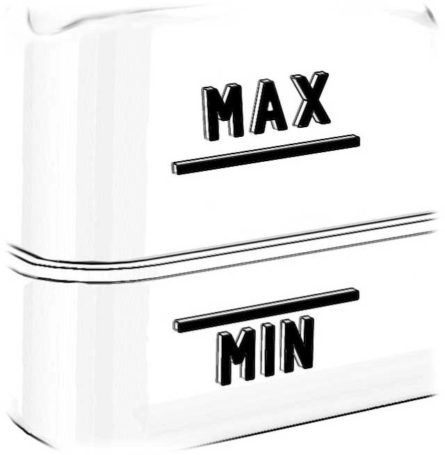
A |
MIN |
A |
Minimum. |
|
B |
MAX |
B |
Nominal. |
|
C |
Maximum. |
E71362
To check the engine oil level consistently and accurately, do the following:
341
Note: Do not remove the dipstick when the engine is running.
Note: If the oil level is between the maximum and minimum marks, the oil level is acceptable. Do not add oil.
Note: The oil consumption of new engines reaches its normal level after approximately 3,000 mi (5,000 km).
|
|
 WARNING: Do not remove the filler cap when the engine is running.
Do not use supplemental engine oil additives because they are unnecessary and could lead to engine damage that may not be covered by the vehicle Warranty.
E142732
Only use oils certified for gasoline engines by the American Petroleum Institute (API). An oil with this trademark symbol conforms to the current engine and emission system protection standards and fuel economy requirements of the International Lubricants Specification Advisory Committee (ILSAC).
To top up the engine oil level do the following:
Note: Do not add oil further than the maximum mark. Oil levels above the maximum mark may cause engine damage.
Note: Make sure you install the oil filler cap correctly.
Note: Soak up any spillage with an absorbent cloth immediately.
342
To check the engine oil level consistently and accurately, do the following:
Note: Do not remove the dipstick when the engine is running.
Note: If the oil level is between the maximum and minimum marks, the oil level is acceptable. Do not add oil.
Note: The oil consumption of new engines reaches its normal level after approximately 3,000 mi (5,000 km).
|
|
 WARNING: Do not remove the filler cap when the engine is running.
Do not use supplemental engine oil additives because they are unnecessary and could lead to engine damage that may not be covered by the vehicle Warranty.
To top up the engine oil level do the following:
Note: Do not add oil further than the maximum mark. Oil levels above the maximum mark may cause engine damage.
Note: Make sure you install the oil filler cap correctly.
Note: Soak up any spillage with an absorbent cloth immediately.
343
The following conditions define severe operation for which engine operation with SAE 5W-40 oil which meets Ford specification, WSS-M2C171-F1, is recommended. Oil and oil filter change intervals will be determined by the Intelligent Oil Life Monitor™ as noted previously.
To check the engine oil level consistently and accurately, do the following:
(page 337).
Note: Do not remove the dipstick when the engine is running.
Note: If the oil level is between the maximum and minimum marks, the oil level is acceptable. Do not add oil.
Note: The oil consumption of new engines reaches its normal level after approximately 3,000 mi (5,000 km).
|
|
 WARNING: Do not remove the filler cap when the engine is running.
Do not use supplemental engine oil additives because they are unnecessary and could lead to engine damage that may not be covered by the vehicle Warranty.

E142732
Only use oils certified for gasoline engines by the American Petroleum Institute (API). An oil with this trademark symbol conforms to the current engine and emission system protection standards and fuel economy requirements of the International Lubricants Specification Advisory Committee (ILSAC).
To top up the engine oil level do the following:
344
Note: Do not add oil further than the maximum mark. Oil levels above the maximum mark may cause engine damage.
Note: Make sure you install the oil filler cap correctly.
Note: Soak up any spillage with an absorbent cloth immediately.
|
|
 WARNING: Do not add engine oil when the engine is hot. Failure to follow this instruction could result in personal injury.
If your vehicle has a diesel engine, an Intelligent Oil Life Monitor™ calculates the proper oil change service interval. When the information display indicates: OIL CHANGE REQUIRED, change the engine oil and oil filter. See Information Displays (page 109).
The engine oil filter protects your engine by filtering harmful, abrasive or sludge particles and particles significantly smaller than most available will-fit filters. See Motorcraft Parts (page 431).
Engine Specifications (page 429).
The following conditions define severe operation:
(-23°C) or above 100°F (38°C).
Only use engine oil that meets our specifications.
Use the information display controls on the steering wheel to reset the oil change indicator.
345
|
Message |
Action and description |
|
Truck Info |
Press the down arrow button, then from this menu scroll to the following message. |
|
Mainten- ance Monitor |
Press the OK button. |
|
Oil Life: xxx% |
Press the down arrow button, then from this menu scroll to the following message. |
|
Oil Life |
Press the OK button. |
|
Oil Life Hold OK to Reset |
Press and hold the OK button until the instrument cluster displays the following message. Oil Life: 100% |
|
When the oil change indic- ator resets the instrument cluster displays 100%. |
|
|
Repeat the process if the oil change indicator does not reset. |
|
|
 WARNING: To reduce the risk of vehicle damage and personal burn injuries, do not start your engine with the air cleaner removed and do not remove it while the engine is running.
Use the correct specification air filter element. See Motorcraft Parts (page 431).
Note: Failure to use the correct air filter element may result in severe engine damage. Resulting component damage may not be covered by the vehicle Warranty.
Change the air filter element at the correct service interval. See Scheduled Maintenance (page 553).
346
|
|
 WARNING: To reduce the risk of vehicle damage and personal burn injuries, do not start your engine with the air cleaner removed and do not remove it while the engine is running.
Use the correct specification air filter element. See Motorcraft Parts (page 434).
Note: Failure to use the correct air filter element may result in severe engine damage. Resulting component damage may not be covered by the vehicle Warranty.
Change the air filter element at the correct service interval. See Scheduled Maintenance (page 553).
E310318
E310319
347
Check the air filter restriction gauge whenever you open the hood to carry out general engine maintenance or at least every 7,500 mi (12,000 km). If you operate your vehicle in extremely dusty conditions, check the gauge at least every 500 mi (800 km) or two weeks, whichever occurs first. Change the air filter element when the restriction gauge reads near the change filter line and the gauge is yellow. Allowing the restriction gauge to reach maximum affects engine performance and fuel economy.
Operating your vehicle in heavy snowfall or extreme rain conditions may allow excessive amounts of snow or water into the air intake system. This could restrict air flow and cause the engine to lose power or shut down.
After installing a new air filter element, you must reset the gauge by pressing the reset button.
After operating your vehicle during heavy snowfall or extreme rain, do the following:
Snow: At the earliest opportunity, open the hood and clear any snow and ice from the air filter housing inlet and reset the air filter restriction gauge.
Extreme rain: The air filter element dries out after approximately 15–30 minutes of driving at highway speeds. At the earliest opportunity, open the hood and reset the air filter restriction gauge.
Note: Do not remove the foam filter.
E310420
The air filter restriction gauge is in the upper housing of the air filter assembly.
348
|
|
 WARNING: To reduce the risk of vehicle damage and personal burn injuries, do not start your engine with the air cleaner removed and do not remove it while the engine is running.
Note: Operating your vehicle in heavy snowfall or extreme rain conditions may allow excessive amounts of snow or water into the air intake system. This could plug or soak the air filter that could cause the engine to lose power or shut down.
When replacing the air filter element, use a Motorcraft® air filter element. See Motorcraft Parts (page 434).
Note: Failure to use the correct air filter element may result in severe engine damage. Resulting component damage may not be covered by the vehicle Warranty.
Change the air filter element at the correct interval. See Scheduled Maintenance (page 553).
E163756
1. Locate the mass air flow sensor electrical connector on the air outlet tube. Disconnect the mass air flow sensor electrical connector.
349
air-tube clamp bolt.
|
|
 WARNING: Do not dispose of fuel in the household refuse or the public sewage system. Use an authorized waste disposal facility.
Your vehicle has a diesel fuel conditioner module. The module is mounted between the outboard side of the fuel tank and the frame rail.
Note: The module is at the front of the fuel tank or at the front of the aft-axle fuel tank on some models.
350
You should drain water from the module assembly whenever the warning light illuminates or a
message appears in the information display advising you to drain the water separator. This occurs when approximately
6.76 fl oz (200 ml) of water accumulates in the module. If you allow the water level
to exceed this level, the water may pass through to the engine and may cause fuel injection equipment damage.
Filter Location
Use the tables below to find the location of your filter.
|
Cab Type |
Box Length |
Filter Location |
|
Regular. |
8 ft (2.4 m) |
Left side of fuel tank. |
|
SuperCab. |
6.75 ft (2.057 m) |
|
|
8 ft (2.4 m) |
In front of fuel tank. |
|
|
Super Crew Cab. |
6.75 ft (2.057 m) |
|
|
8 ft (2.4 m) |
Left side of fuel tank. |
|
Cab Type |
Fuel Tank Type |
Filter Location |
|
Chassis Cab. |
Single midship fuel tank |
Right side of fuel tank. |
|
Chassis Cab. |
Aft axle/midship fuel tanks |
Right side of midship fuel tank. |
|
Chassis Cab. |
Single aft axle fuel tank |
Front of fuel tank. |
Draining the Diesel Fuel Conditioner Module
351
352
|
|
 WARNING: Do not remove the coolant reservoir cap when the engine is on or the cooling system is hot. Wait 10 minutes for the cooling system to cool down. Cover the coolant reservoir cap with a thick cloth to prevent the possibility of scalding and slowly remove the cap. Failure to follow this instruction could result in personal injury.
 WARNING: Do not put coolant in the windshield washer reservoir. If sprayed on the windshield, coolant could make it difficult to see through the windshield.
 WARNING: To reduce the risk of personal injury, make sure the engine is cool before unscrewing the coolant pressure relief cap. The cooling system is under pressure. Steam and hot liquid can come out forcefully when you loosen the cap slightly.
 WARNING: Do not add coolant further than the MAX mark.
When the engine is cold, check the concentration and level of the coolant at the intervals listed in the scheduled maintenance information. See Scheduled Maintenance (page 553).
Note: Make sure that the coolant level is between the MIN and the MAX marks on the coolant reservoir.
Note: Coolant expands when it is hot. The level may extend beyond the MAX mark.
Maintain coolant concentration within 48% to 50%, which equates to a freeze point between -30°F (-34°C) and -34°F (-37°C). Coolant concentration should be checked using a refractometer. We recommend Robinair® Coolant and Battery Refractometer 75240 (Rotunda tool part number: ROB75240). We do not recommend the use of hydrometers or coolant test strips for measuring coolant concentration.
Note: Automotive fluids are not interchangeable. Do not use coolant or windshield washer fluid outside of its specified function and vehicle location.
Note: Do not use stop leak pellets, cooling system sealants, or additives as they can cause damage to the engine cooling or heating systems. Resulting component damage may not be covered by the vehicle Warranty.
|
|
 WARNING: Do not remove the coolant reservoir cap when the engine is on or the cooling system is hot. Wait 10 minutes for the cooling system to cool down. Cover the coolant reservoir cap with a thick cloth to prevent the possibility of scalding and slowly remove the cap. Failure to follow this instruction could result in personal injury.
It is very important to use prediluted coolant meeting the correct specification in order to avoid plugging the small passageways in the engine cooling system. See Capacities and Specifications (page 437). Incorrect prediluted coolant use can cause damage not covered by the vehicle Warranty.
If the coolant level is at or below the minimum mark, add prediluted coolant immediately.
353
To top up the coolant level do the following:
Do not mix different colors or types of prediluted coolant in your vehicle. Mixing of prediluted coolant or using an incorrect prediluted coolant may harm the engine or cooling system components and may not be covered by the vehicle Warranty.
If you have to add more than 1.1 qt (1 L) of engine coolant per month, have your vehicle checked as soon as possible.
Operating an engine with a low level of coolant can result in engine overheating and possible engine damage.
In case of emergency, you can add a large amount of water without prediluted coolant in order to reach a vehicle service location. On arrival do the following:
Water alone, without prediluted coolant, can cause engine damage from corrosion, overheating or freezing.
Do not use the following as a coolant substitute:
Alcohol.
Methanol.
Brine.
Any coolant mixed with alcohol or methanol antifreeze.
Alcohol and other liquids can cause engine damage from overheating or freezing.
Do not add extra inhibitors or additives to the coolant. These can be harmful and compromise the corrosion protection of the coolant.
We do not recommend the use of recycled coolant as an approved recycling process is not yet available.
Dispose of used engine coolant in an appropriate manner. Follow your community’s regulations and standards for recycling and disposing of automotive fluids.
If you drive in extremely cold climates:
It may be necessary to increase the coolant concentration above 50%.
A coolant concentration of 60% provides improved freeze point protection. Coolant concentrations above 60% decrease the overheat protection characteristics of the coolant and may cause engine damage.
354
If you drive in extremely hot climates:
It may be necessary to decrease the coolant concentration to 40%.
A coolant concentration of 40% provides improved overheat protection. Coolant concentrations below 40% decrease the freeze and corrosion protection characteristics of the coolant and may cause engine damage.
Vehicles driven year-round in non-extreme climates should use prediluted coolant for optimum cooling system and engine protection.
Fail-safe cooling allows you to temporarily drive your vehicle before any incremental component damage occurs. The fail-safe distance depends on ambient temperature, vehicle load and terrain.
If the engine begins to overheat, the coolant temperature gauge moves toward the red zone:
A warning lamp illuminates and a message may appear in the information display.
If the engine reaches a preset
over-temperature condition, the engine automatically switches to alternating cylinder operation. Each disabled cylinder acts as an air pump and cools the engine.
When this occurs, your vehicle still operates, however:
Engine power is limited.
The air conditioning system turns off.
Continued operation increases the engine temperature, causing the engine to completely shut down. Your steering and braking effort increases in this situation.
When the engine temperature cools, you can re-start the engine. Have your vehicle checked as soon as possible to minimize engine damage.
|
completely shut down without warning, potentially losing engine power, power steering assist, and power brake assist, which may increase the possibility of a crash resulting in serious injury.
|
 WARNING: Fail-safe mode is for use during emergencies only. Operate your vehicle in fail-safe mode only as long as necessary to bring your vehicle to rest in a safe location and seek immediate repairs. When in fail-safe mode, your vehicle will have limited power, will not be able to maintain high-speed operation, and may
 WARNING: Do not remove the coolant reservoir cap when the engine is on or the cooling system is hot. Wait 10 minutes for the cooling system to cool down. Cover the coolant reservoir cap with a thick cloth to prevent the possibility of scalding and slowly remove the cap. Failure to follow this instruction could result in personal injury.
Your vehicle has limited engine power when in the fail-safe mode, drive your vehicle with caution. Your vehicle does not maintain high-speed operation and the engine may operate poorly.
Remember that the engine is capable of automatically shutting down to prevent engine damage. In this situation:
355
Note: Driving your vehicle without repair increases the chance of engine damage.
Engine Coolant Temperature Management (If Equipped)
|
|
 WARNING: To reduce the risk of crash and injury, be prepared that the vehicle speed may reduce and the vehicle may not be able to accelerate with full power until the coolant temperature reduces.
If you tow a trailer with your vehicle, the engine may temporarily reach a higher temperature during severe operating conditions, for example ascending a long or steep grade in high ambient temperatures.
At this time, you may notice the coolant temperature gauge moves toward the red zone and a message may appear in the information display.
You may notice a reduction in vehicle speed caused by reduced engine power in order to manage the engine coolant temperature. Your vehicle may enter this mode if certain high-temperature and high-load conditions take place. The amount of speed reduction depends on vehicle loading, grade and ambient temperature. If this occurs, there is no need to pull off the road. You can continue to drive your vehicle.
The air conditioning may automatically turn on and off during severe operating conditions to protect the engine from overheating. When the coolant temperature decreases to the normal operating temperature, the air conditioning turns on.
If the coolant temperature gauge moves fully into the red zone, or if the coolant temperature warning or service engine soon messages appear in your information display, do the following:
356
|
|
 WARNING: Do not remove the coolant reservoir cap when the engine is on or the cooling system is hot. Wait 10 minutes for the cooling system to cool down. Cover the coolant reservoir cap with a thick cloth to prevent the possibility of scalding and slowly remove the cap. Failure to follow this instruction could result in personal injury.
 WARNING: Do not put coolant in the windshield washer reservoir. If sprayed on the windshield, coolant could make it difficult to see through the windshield.
 WARNING: To reduce the risk of personal injury, make sure the engine is cool before unscrewing the coolant pressure relief cap. The cooling system is under pressure. Steam and hot liquid can come out forcefully when you loosen the cap slightly.
 WARNING: Do not add coolant further than the MAX mark.
When the engine is cold, check the concentration and level of the coolant at the intervals listed in the scheduled maintenance information. See Scheduled Maintenance (page 553).
Note: Make sure that the coolant level is between the MIN and MAX marks on the coolant reservoir.
Note: Coolant expands when it is hot. The level may extend beyond the MAX mark.
Maintain coolant concentration within 48% to 50%, which equates to a freeze point between -30°F (-34°C) and -34°F (-37°C). Check the coolant concentration using a refractometer. We do not recommend the use of hydrometers or coolant test strips for measuring coolant concentration.
|
|
 WARNING: Do not add engine coolant when the engine is on or the cooling system is hot. Failure to follow this instruction could result in personal injury.
 WARNING: Do not remove the coolant reservoir cap when the engine is on or the cooling system is hot. Wait 10 minutes for the cooling system to cool down. Cover the coolant reservoir cap with a thick cloth to prevent the possibility of scalding and slowly remove the cap. Failure to follow this instruction could result in personal injury.
Note: Automotive fluids are not interchangeable. Do not use coolant or windshield washer fluid outside of its specified function and vehicle location.
Note: Do not use stop leak pellets, cooling system sealants, or additives as they can cause damage to the engine cooling or heating systems. Resulting component damage may not be covered by the vehicle Warranty.
357
It is very important to use prediluted coolant approved to the correct specification to avoid plugging the small passageways in the engine cooling system. See Capacities and Specifications (page 446). Do not mix different colors or types of coolant in your vehicle. Mixing of engine coolants or using an incorrect coolant may harm the engine or cooling system components and may not be covered by the vehicle Warranty.
Note: Coolants marketed for all makes and models may not be approved to our specifications and may cause damage to the cooling system. Resulting component damage may not be covered by the vehicle Warranty.
If the coolant level is at or below the minimum mark, immediately add prediluted coolant.
For vehicles with overflow coolant systems with a non-pressurized cap on the coolant recovery system, add coolant to the coolant recovery reservoir when the engine is cool. Add prediluted coolant to the maximum level. For all vehicles which have a coolant degas system with a pressurized cap, or if it is necessary to remove the coolant pressure relief cap on the radiator, follow these steps to add engine coolant:
Note: If prediluted coolant is not available, use the approved antifreeze concentrate diluting it to 50/50 with distilled water. See Capacities and Specifications (page 446). Using water that has not been deionized may contribute to deposit formation, corrosion or plugging of the small cooling system passageways.
If you have to add more than 1.1 qt (1 L) of engine coolant per month, have your vehicle checked as soon as possible.
Operating an engine with a low level of coolant can result in engine overheating and possible engine damage.
In case of emergency, you can add a large amount of water without prediluted coolant in order to reach a vehicle service location. On arrival do the following:
Water alone, without prediluted coolant, can cause engine damage from corrosion, overheating or freezing.
Do not use the following as a coolant substitute:
Alcohol.
Methanol.
Brine.
Any coolant mixed with alcohol or methanol antifreeze.
358
Alcohol and other liquids can cause engine damage from overheating or freezing.
Do not add extra inhibitors or non-specified additives to the coolant. These can be harmful and compromise the corrosion protection of the coolant.
Perform this procedure when refilling the engine or secondary cooling systems after it has been drained or become extremely low:
We do not recommend the use of recycled coolant as an approved recycling process is not yet available.
Dispose of used engine coolant in an appropriate manner. Follow your community’s regulations and standards for recycling and disposing of automotive fluids.
359
If you drive in extremely cold climates:
It may be necessary to increase the coolant concentration above 50%.
A coolant concentration of 60% provides improved freeze point protection. Coolant concentrations above 60% decrease the overheat protection characteristics of the coolant and may cause engine damage.
If you drive in extremely hot climates:
You can decrease the coolant concentration to 40%.
Coolant concentrations below 40% decrease the freeze and corrosion protection characteristics of the coolant and may cause engine damage.
Vehicles driven year-round in non-extreme climates should use prediluted engine coolant for optimum cooling system and engine protection.
Follow the specific mileage intervals, as listed in the scheduled maintenance information, to change the coolant. The information display may display a message to change coolant at this time. Add prediluted coolant approved to the correct specification. See Capacities and Specifications (page 429).
Your vehicle may have an engine driven cooling fan drive also called a fan clutch. This fan drive changes the fan speed to match the vehicle’s changing cooling air flow requirements. Fan speed, fan noise level and fuel consumption all will increase based on the driving conditions that include trailer towing, hill climbing, heavy loads, high speed and high ambient temperature, individually or in combination.
The fan drive is designed to provide the minimum fan speed and resulting minimum fan noise and fuel consumption required to meet the ever-changing vehicle cooling air flow requirements. You can hear the amount of fan noise increasing and decreasing as the engine power requirements and vehicle driving conditions change as you drive. This is normal to the operation of your vehicle. You may also hear high levels of the fan when the engine is first started and should normally decrease after driving for a short time.


360
|
|
 WARNING: Do not remove the coolant reservoir cap when the engine is on or the cooling system is hot. Wait 10 minutes for the cooling system to cool down. Cover the coolant reservoir cap with a thick cloth to prevent the possibility of scalding and slowly remove the cap. Failure to follow this instruction could result in personal injury.
 When the engine is cold, check the concentration and level of the coolant at the intervals listed in the scheduled maintenance information. See Scheduled Maintenance (page 553).
Note: Make sure that the coolant level is between the MIN and MAX marks on the coolant reservoir.
Note: Coolant expands when it is hot. The level may extend beyond the MAX mark.
Maintain coolant concentration within 48% to 50%, which equates to a freeze point between -30°F (-34°C) and -34°F (-37°C). Check the coolant concentration using a refractometer. We do not recommend the use of hydrometers or coolant test strips for measuring coolant concentration.

Note: Automotive fluids are not interchangeable. Do not use coolant or windshield washer fluid outside of its specified function and vehicle location.
Note: Do not use stop leak pellets, cooling system sealants, or non-specified additives as they can cause damage to the engine cooling or heating systems. Resulting component damage may not be covered by the vehicle Warranty.
It is very important to use prediluted coolant approved to the correct specification in order to avoid plugging the small passageways in the engine cooling system. See Capacities and Specifications (page 457). Do not mix different colors or types of coolant in your vehicle. Mixing of engine coolants or using an incorrect coolant may harm the engine or cooling system components and may not be covered by the vehicle Warranty.
Note: Coolants marketed for all makes and models may not be approved to our specifications and may cause damage to the cooling system. Resulting component damage may not be covered by the vehicle Warranty.
If the coolant level is at or below the minimum mark, add prediluted coolant immediately.
361
For vehicles with overflow coolant systems with a non-pressurized cap on the coolant recovery system, add coolant to the coolant recovery reservoir when the engine is cool. Add prediluted coolant to the maximum level. For all vehicles which have a coolant degas system with a pressurized cap, or if it is necessary to remove the coolant pressure relief cap on the radiator, follow these steps to add engine coolant:
Note: If prediluted coolant is not available, use the approved antifreeze concentrate diluting it to 50/50 with distilled water. See Capacities and Specifications (page 457). Using water that has not been deionized may contribute to deposit formation, corrosion or plugging of the small cooling system passageways.
If you have to add more than 1.1 qt (1 L) of engine coolant per month, have your vehicle checked as soon as possible.
Operating an engine with a low level of coolant can result in engine overheating and possible engine damage.
Note: During normal vehicle operation, the coolant may change color from orange to pink or light red. As long as the coolant is clear and uncontaminated, this color change does not indicate the coolant has degraded nor does it require the coolant to be drained, the system to be flushed, or the coolant to be replaced.
Note: In case of emergency, you can add a large amount of water without coolant in order to reach a vehicle service location.
Water alone, without coolant, can cause engine damage from corrosion, overheating or freezing. When you reach a service location, you must have the cooling system drained, flushed and refilled using the correct specification prediluted coolant or antifreeze concentrate. See Capacities and Specifications (page 457).
Do not use the following as a coolant substitute:
Alcohol.
Methanol.
Brine.
Any coolant mixed with alcohol or methanol antifreeze.
Alcohol and other liquids can cause engine damage from overheating or freezing.
Do not add extra inhibitors or additives to the coolant. These can be harmful and compromise the corrosion protection of the coolant.
We do not recommend the use of recycled coolant as an approved recycling process is not yet available.
362
Dispose of used engine coolant in an appropriate manner. Follow your community’s regulations and standards for recycling and disposing of automotive fluids.
If you drive in extremely cold climates:
It may be necessary to increase the coolant concentration above 50%.
A coolant concentration of 60% provides improved freeze point protection. Coolant concentrations above 60% decrease the overheat protection characteristics of the coolant and may cause engine damage.
If you drive in extremely hot climates:
You can decrease the coolant concentration to 40%.
Coolant concentrations below 40% decrease the freeze and corrosion protection characteristics of the coolant and may cause engine damage.
Vehicles driven year-round in non-extreme climates should use prediluted engine coolant for optimum cooling system and engine protection.
Change the coolant at specific mileage intervals as listed in the scheduled maintenance information. The information display may display a message to change coolant at this time. Add prediluted coolant approved to the correct specification. See Capacities and Specifications (page 429).
Your vehicle comes with an engine driven cooling fan drive, also called a fan clutch. This fan drive changes the fan speed to match the vehicle’s changing cooling air flow requirements. Fan speed, fan noise level and fuel consumption all will increase based on the driving conditions that include trailer towing, hill climbing, heavy loads, high speed and high ambient temperature, individually or in combination.
The fan drive is designed to provide the minimum fan speed, and resulting minimum fan noise and fuel consumption required to meet the ever changing vehicle cooling air flow requirements. You will hear the amount of fan noise increasing and decreasing as the engine power requirements and vehicle driving conditions change as you drive. This is to be expected as being normal to the operation of your vehicle. High levels of fan noise might also be heard when your engine is first started, and should normally decrease after driving for a short time.
Fail-safe cooling allows you to temporarily drive your vehicle before any incremental component damage occurs. The fail-safe distance depends on ambient temperature, vehicle load and terrain.
If the engine begins to overheat, the coolant temperature gauge moves toward the red zone:
A warning lamp illuminates and a message may appear in the information display.
363
If the engine reaches a preset
over-temperature condition, the engine switches to alternating cylinder operation. Each disabled cylinder acts as an air pump and cools the engine.
When this occurs, your vehicle still operates, however:
Engine power is limited.
The air conditioning system turns off.
Continued operation increases the engine temperature, causing the engine to completely shut down. Your steering and braking effort increases in this situation.
When the engine temperature cools, you can re-start the engine. Have your vehicle checked as soon as possible to minimize engine damage.
|
completely shut down without warning, potentially losing engine power, power steering assist, and power brake assist, which may increase the possibility of a crash resulting in serious injury.
|
 WARNING: Fail-safe mode is for use during emergencies only. Operate your vehicle in fail-safe mode only as long as necessary to bring your vehicle to rest in a safe location and seek immediate repairs. When in fail-safe mode, your vehicle will have limited power, will not be able to maintain high-speed operation, and may
 WARNING: Do not remove the coolant reservoir cap when the engine is on or the cooling system is hot. Wait 10 minutes for the cooling system to cool down. Cover the coolant reservoir cap with a thick cloth to prevent the possibility of scalding and slowly remove the cap. Failure to follow this instruction could result in personal injury.
364
Your vehicle has limited engine power when in the fail-safe mode, drive your vehicle with caution. Your vehicle does not maintain high-speed operation and the engine may operate poorly.
Remember that the engine is capable of shutting down to prevent engine damage. In this situation:
Note: Driving your vehicle without repair increases the chance of engine damage.
Engine Coolant Temperature Management (If Equipped)
|
|
 WARNING: To reduce the risk of crash and injury, be prepared that the vehicle speed may reduce and the vehicle may not be able to accelerate with full power until the coolant temperature reduces.
If you tow a trailer with your vehicle, the engine may temporarily reach a higher temperature during severe operating conditions, for example ascending a long or steep grade in high ambient temperatures.
At this time, you may notice the coolant temperature gauge moves toward the red zone and a message may appear in the information display.
You may notice a reduction in vehicle speed caused by reduced engine power in order to manage the engine coolant temperature. Your vehicle may enter this mode if certain high-temperature and high-load conditions take place. The amount of speed reduction depends on vehicle loading, grade and ambient temperature. If this occurs, there is no need to pull off the road. You can continue to drive your vehicle.
The air conditioning may turn on and off during severe operating conditions to protect the engine from overheating. When the coolant temperature decreases to the normal operating temperature, the air conditioning turns on.
If the coolant temperature gauge moves fully into the red zone, or if the coolant temperature warning or service engine soon messages appear in your information display, do the following:
The automatic transmission does not have a transmission fluid dipstick.
Your transmission is filled for life, and does not need to be checked. Your transmission does not consume fluid. However, if the transmission slips or shifts slowly, or if you notice some sign of fluid leakage, have your vehicle checked as soon as possible.
Do not use supplemental transmission fluid additives, treatments or cleaning agents. The use of these materials may affect transmission operation and result in damage to internal transmission components.
365
TRANSFER CASE FLUID CHECK (IF EQUIPPED)
E164246
Only use fluid that meets Ford specifications. See Capacities and Specifications (page 429).
|
|
 WARNING: Do not use any fluid other than the recommended brake fluid as this will reduce brake efficiency. Use of incorrect fluid could result in the loss of vehicle control, serious personal injury or death.
 WARNING: Only use brake fluid from a sealed container. Contamination with dirt, water, petroleum products or other materials may result in brake system damage or failure. Failure to adhere to this warning could result in the loss of vehicle control, serious personal injury or death.
 WARNING: Do not allow the fluid to touch your skin or eyes. If this happens, rinse the affected areas immediately with plenty of water and contact your physician.
 WARNING: The brake system could be affected if the brake fluid level is below the MIN mark or above the MAX mark on the brake fluid reservoir.
366
E170684
Note: If the brake fluid level is between the MIN and the MAX marks on the reservoir, it is acceptable.
Note: If the brake fluid level is below the MIN mark or above the MAX mark, have your vehicle checked as soon as possible.
Note: To avoid fluid contamination, the reservoir cap must remain in place and fully tight, unless you are adding fluid.
Only use fluid that meets our specifications. See Capacities and Specifications (page 429).
Brake fluid absorbs water over time which degrades the effectiveness of the brake fluid. Change the brake fluid at the specified intervals to prevent degraded braking performance.
For detailed interval information, see Scheduled Maintenance in your Owner's Manual or your local maintenance guide.
Check the power steering fluid. See Scheduled Maintenance (page 553). If adding fluid is necessary, use only MERCON LV ATF
Check the fluid level when it is at ambient temperature.
367


|
Failure to do so may cause serious personal injury or property damage. |
 WARNING: This vehicle may have more than one battery. Removing the battery cables from only one battery does not disconnect your vehicle electrical system. Make sure you disconnect the battery cables from all batteries when disconnecting power.
Your vehicle is fitted with a Motorcraft maintenance-free battery which normally does not require additional water.
When a battery replacement is required, you must use a recommended replacement battery that matches the electrical requirements of the vehicle.
Note: After cleaning or replacing the battery, make sure you reinstall the battery vent tube, battery cover or shield.
For longer, trouble-free operation, keep the top of the battery clean and dry.
If you see any corrosion on the battery or terminals, remove the cables from the terminals and clean with a wire brush. You can neutralize the acid with a solution of baking soda and water.
Because your vehicle’s engine is electronically controlled by a computer, some control conditions are maintained by power from the battery. When the battery is disconnected or a new battery is installed, the engine must relearn its idle and fuel trim strategy for optimum driveability and performance. Flexible fuel vehicles (FFV) must also relearn the ethanol content of the fuel for optimum driveability and performance.
To restore the settings, do the following:
368
Note: If you do not allow the engine to relearn the idle and fuel trim strategy, the idle quality of your vehicle may be adversely affected until the engine computer eventually relearns the idle trim and fuel trim strategy.
Note: For flexible fuel vehicles, if you are operating on E85, you may experience poor starts or an inability to start the engine and driveability problems until the fuel trim and ethanol content have been relearned.
Make sure that you dispose of old batteries in an environmentally friendly way. Seek advice from your local authority about recycling old batteries.
If storing your vehicle for more than 30 days without recharging the battery, we recommend that you disconnect the negative battery cable to maintain battery charge for quick starting.
Battery Management System (If Equipped)
The battery management system monitors battery conditions and takes actions to extend battery life. If excessive battery drain is detected, the system temporarily disables some electrical systems to protect the battery.
Systems included are:
A message may appear in the information displays to alert you that battery protection actions are active. These messages are only for notification that an action is taking place, and not intended to indicate an electrical problem or that the battery requires replacement.
After battery replacement, or in some cases after charging the battery with an external charger, the battery management system requires eight hours of vehicle sleep time to relearn the battery state of charge. During this time your vehicle must remain fully locked with the ignition switched off.
Note: Prior to relearning the battery state of charge, the battery management system may temporarily disable some electrical systems.
To make sure the battery management system works correctly, do not connect an electrical device ground connection directly to the battery negative post. This can cause inaccurate measurements of the battery condition and potential incorrect system operation.
Note: If you add electrical accessories or components to the vehicle, it may adversely affect battery performance and durability. This may also affect the performance of other electrical systems in the vehicle.
369
 The headlamps on your vehicle are properly aimed at the assembly plant. If your vehicle has been in an accident, the alignment of your headlamps should be checked by your authorized dealer.
D Horizontal reference line
E142465
A
Note: To see a clearer light pattern for adjusting, you may want to block the light from one headlamp while adjusting the other.
E223774
Note: A. LED headlamp.
370
B. Halogen headlamp.
Horizontal Aim Adjustment
Horizontal aim is not required for this vehicle and is not adjustable.
|
|
 WARNING: If you operate your vehicle in temperatures below 40°F (5°C), use washer fluid with antifreeze protection. Failure to use washer fluid with antifreeze protection in cold weather could result in impaired windshield vision and increase the risk of injury or accident.
Add fluid to fill the reservoir if the level is low. Only use a washer fluid that meets Ford specifications. See Capacities and Specifications (page 429).
State or local regulations on volatile organic compounds may restrict the use of methanol, a common windshield washer antifreeze additive. Washer fluids containing non-methanol antifreeze agents should be used only if they provide cold weather protection without damaging the vehicle’s paint finish, wiper blades or washer system.
Your vehicle is equipped with a lifetime fuel filter that is integrated with the fuel tank. Regular maintenance or replacement is not needed.
E142463
Run the tip of your fingers over the edge of the blade to check for roughness.
Clean the wiper blades with washer fluid or water applied with a soft sponge or cloth.
You can manually move the wiper arms when the ignition is off. This allows for ease of blade replacement and cleaning under the blades.
1. Pull the wiper blade and arm away from the glass.
371
Note: To access the right-hand side bulbs, remove the air intake pipe. See Changing the Engine Air Filter (page 346).
To access the left-hand side bulbs, remove the washer reservoir filler tube. Vehicles with diesel engine only.
E165794
Note: Make sure that the wiper blade locks into place. Lower the wiper arm and blade back on the windshield. The wiper arms will automatically return to their normal position when you turn the ignition on.
|
|
 WARNING: Switch the lamps and the ignition off. Failure to follow this warning could result in serious personal injury.
 WARNING: Bulbs can become hot. Let the bulb cool down before removing it. Failure to do so could result in personal injury.
Use the correct specification bulb. See Bulb Specification Chart (page 467). Install in the reverse order unless otherwise stated.
E224990
Note: You cannot separate the bulb from the bulb holder.
Note: To access the right-hand side bulbs, remove the air intake pipe. See Changing the Engine Air Filter (page 346).
To access the left-hand side bulbs, remove the washer reservoir filler tube. Vehicles with diesel engine only.
372
E224991
Note: You cannot separate the bulb from the bulb holder.
Note: Handle a halogen headlamp bulb carefully and keep out of children’s reach. Grasp the bulb only by its plastic base and do not touch the glass. The oil from your hand could cause the bulb to break the next time the headlamps are operated.
Fog Lamp Bulbs (If Equipped)
E163826
Note: You cannot separate the bulb from the bulb holder.
Note: Handle a halogen bulb carefully and keep out of children’s reach. Grasp the bulb only by its plastic base and do not touch the glass. The oil from your hand could cause the bulb to break the next time the fog lamps are operated.
373
Chassis Cabs
4
E224204
E163828
the lamp assembly from the vehicle to expose the bulb sockets.
E187290
374
4. Remove the bulb by pulling it straight out.
LED Lamps (If Equipped)
LED lamps are not serviceable items. See an authorized dealer if they fail.
The following lamps may be LED:
|
|
 WARNING: Do not dispose of fuel in the household refuse or the public sewage system. Use an authorized waste disposal facility.
Your vehicle has two fuel filters. The first filter mounts on top of the engine on the left-hand side. The second filter is inside the diesel fuel conditioner module. The module is attached to the fuel tank in different locations depending on the configuration of your truck. See table below for configurations.
Note: The module is at the front of the fuel tank or at the front of the aft-axle fuel tank on some models.
Regular fuel filter changes are an important part of engine maintenance; failing to keep with the scheduled maintenance could lead to engine performance issues and fuel injection system damage. See Scheduled Maintenance (page 553).
Use only recommended service parts conforming to specifications. See Motorcraft Parts (page 433).
Note: Using fuel that has high levels of impurities may require more frequent filter replacements than the service interval specifies.
Use the tables below to find the location of your filter.
375
|
Cab Type |
Box Length |
Filter Location |
|
Regular. |
8 ft (2.4 m) |
Left side of fuel tank. |
|
SuperCab. |
6.75 ft (2.057 m) |
|
|
8 ft (2.4 m) |
In front of fuel tank. |
|
|
Super Crew Cab. |
6.75 ft (2.057 m) |
|
|
8 ft (2.4 m) |
Left side of fuel tank. |
Chassis Cab
|
Cab Type |
Fuel Tank Type |
Filter Location |
|
Chassis Cab. |
Single midship fuel tank |
Right side of fuel tank. |
|
Chassis Cab. |
Aft axle/midship fuel tanks |
Right side of midship fuel tank. |
|
Chassis Cab. |
Single aft axle fuel tank |
Front of fuel tank. |
Removal
E247666
376
Note: Do not fully remove the bolts from the lower portion of the diesel fuel conditioner module housing.
E269862
E269863
7. Slide the filter element toward the drain plug to disengage the securing clips.
(9 Nm).
377
Although the fuel system is not fully pressurized when the vehicle is off, some residual pressure may remain in the fuel system since it can take some time for the pressure to completely bleed off.
Therefore, we recommend you place an absorbent cloth below the filter connectors to absorb any fuel that may drain.
The engine-mounted fuel filter is a plastic disposable cartridge.
E226215
Note: No special air purge is necessary after filter servicing. The fuel system purges the air in the filters.
Check and tighten the U-bolt nuts after your vehicle has been operated under load for 1,000 mi (1,600 km) or six months, whichever occurs first.
Check and tighten the U-bolt nuts every 37,000 mi (60,000 km).
378
Check and tighten the U-bolt nuts with your vehicle at curb height and unloaded.
Inspect the U-bolt threads for rust and debris. Clean the threads if contaminated.
Note: Check and tighten the U-bolt nuts evenly using a criss-cross pattern in the following stages.
|
Stage |
lb.ft (Nm) |
|
1. |
70 lb.ft (100 Nm) |
|
2. |
150 lb.ft (200 Nm) |
|
3. |
220 lb.ft (300 Nm) |
|
4. |
300 lb.ft (400 Nm) |
379
Download Manual