Towing
|
the WARNING: Do not exceed GVWR or the GAWR specified on the certification label. bey WARNING: Towing trailers ond the maximum recommended gross trailer weight exceeds the limit of your vehicle and could result in engine damage, transmission damage, structural damage, loss of vehicle control, vehicle rollover and personal injury. the l WARNING: Do not exceed owest rating capacity for your vehicle or trailer hitch. Overloading your vehicle or trailer hitch can impair your vehicle stability and handling. Failure to follow this instruction could result in the loss of control of your vehicle, personal injury or death. wel WARNING: Do not cut, drill, d or modify the trailer hitch. Modifying the trailer hitch could reduce the hitch rating. |
273
Note: To prevent your trailer from accumulating distance, and the trailer information status appearing when you restart your vehicle after disconnecting your trailer, you must deactivate your trailer. Using the information display, go to the Towing menu and then the Select Trailer option. Select the No active trailer option. See Information Displays (page 112).
Your vehicle may have electrical items, such as fuses or relays, related to towing. See Fuses (page 318).
Your vehicle may have ability to modify trailer towing features. See General Information (page 112).
Your vehicle's load capacity designation is by weight, not by volume, so you cannot necessarily use all available space when loading a vehicle or trailer.
Towing a trailer places an extra load on your vehicle's engine, transmission, axle, brakes, tires and suspension. Inspect these components periodically during, and after, any towing operation.
Load Placement
To help minimize how trailer movement affects your vehicle when driving:
• Load the heaviest items closest to the trailer floor.
• Load the heaviest items centered between the left and right side trailer tires.
• Load the heaviest items above the trailer axles or just slightly forward toward the trailer tongue. Do not allow the final trailer tongue weight to go above or below 10-15% of the loaded trailer weight.
• Select a ball mount with the correct rise or drop. When both the loaded vehicle and trailer are connected, the trailer frame should be level, or slightly angled down toward your vehicle, when viewed from the side.
When driving with a trailer or payload, a slight takeoff vibration or shudder may be present due to the increased payload weight.
Additional information regarding proper trailer loading and setting your vehicle up for towing is located in another chapter of this manual. See Load Limit (page 266).
You can also find information in the RV & Trailer Towing Guide available at your authorized dealer, or online.
|
RV & Trailer Towing Guide Online |
|
|
Website |
h t tp: / / ww w .f l ee t. f o r d . c om / t o wing- g uid e s/ |
274
|
|
 WARNING: Driving while distracted can result in loss of vehicle control, crash and injury. We strongly recommend that you use extreme caution when using any device that may take your focus off the road. Your primary responsibility is the safe operation of your vehicle. We recommend against the use of any hand-held device while driving and encourage the use of voice-operated systems when possible. Make sure you are aware of all applicable local laws that may affect the use of electronic devices while driving.
Note: You must always be aware of the vehicle and trailer combination and the surrounding environment.
Note: The system does not detect or prevent the vehicle or trailer from making contact with obstacles in the surrounding environment.
Note: Keep in mind that the front end of the vehicle swings out when changing the direction of the trailer.
Note: The system relies on user measurements to determine sticker placement and system limits. It is critical to take the key measurements correctly.
Incorrect measurements can result in the improper function of the system up to and including contact between the vehicle and trailer.
Note: The system limits vehicle speed when backing up. The system is not a replacement for proper use of the throttle and brake pedals.
Note: Some features associated with this system do not work until you set it up.
Trailer reverse guidance is a driver assistance feature that helps take the guesswork out of getting your trailer positioned where you want it, quickly and easily, when driving in reverse (R).
Each trailer you use with your vehicle has to be setup once. Sticker placement is extremely important and there are specific placement rules.
Note: Your vehicle saves the trailer information when you enter it into the system. A maximum of 10 trailers can be added to the system.
Hitch your trailer to the truck and connect the electrical wiring harness. Check to make sure that the wiring is working. See Essential Towing Checks (page 287).
Park your vehicle and hitched trailer on a level surface.
E209759
Make sure that the trailer and truck are in line with each other. You can do this by putting the truck in drive (D) and pulling straight forward.
E209760
275
Note: The default option is low. This is recommended for most trailers. If the trailer's brakes require more initial voltage, or if you prefer more aggressive braking, then select the other options as required.
Note: You can still manually control the camera views on the touchscreen to help you reverse goose neck and fifth wheel trailers.
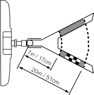
Place the entire sticker in the gray zone on the trailer outlined in the diagram. The sticker is in the back cover pocket of the quick start guide.
Note: An assistant can help to carry out the following procedure.
Note: Make sure nothing obstructs the rear view cameras view of the sticker. For example, items such as a jack handle or wiring.
Note: Position the sticker on a flat, dry and clean horizontal surface. For best results apply the sticker when temperatures are above 32°F (0°C).
Note: Do not move stickers after they are placed. Do not re-use any stickers if removed.
E224482
276
Use the supplied measurement card, a tape measure and pen to carefully mark the area where to attach the sticker. The sticker is supplied in the back cover pocket of your quick start guide. Make sure the entire sticker is within the gray zone between the two arcs or distance markers on the diagram, and is also visible in the rear view camera display. It should be between 7–20 in (17–51 cm) from the trailer ball hitch.
Once you have found the correct location, place the sticker.
After you place the sticker on the trailer you must take some measurements.
Note: You must take accurate measurements for the system to operate properly.
Note: Round measurement figures to the nearest half inch.
Note: Round upward if the measured length is a quarter inch or greater. Round downward if the measure length is less than a quarter inch. For example 12.25 in
(31.11 cm) would be rounded up to 12.50 in (31.75 cm). 12.13 in (30.8 cm) would be rounded down to 12.00 in (30.48 cm).
Note: Use consistent metric or imperial units as required by your country or vehicle.
The measurement card requires you to record four key distances (A, B, C, D). Record the trailer name for these measurements.
The horizontal distance from the license plate to the center of the ball hitch on the trailer.
The horizontal distance from the center of the ball hitch to the center of the sticker.
The distance from the rear view camera to the center of the sticker.
The distance from the tailgate to the center of the trailer axle (single axle trailers), or the center of the axles (trailers with dual axles or more).
277
Using the measurements you recorded, enter the required data into the system. Follow the on screen prompts to enter each of the measurements taken in step
4. Use the up and down arrows to increase or decrease the numbers as necessary. Press OK to confirm each measurement. Once you add the last measurement, the information display shows all of the entered measurements. You can choose to confirm or change the measurements.
Check the rear view camera display to see if the system identifies the sticker. The system marks the sticker with a red circle. Confirm that the red circle shows over the sticker image in the rear view camera display.
Note: If the system cannot locate the sticker, try cleaning the camera lens. Make sure the sticker is within the zone as indicated in step 3.
The information display shows a confirmation message when you successfully confirm the target.
To complete setup, drive your vehicle straight forward between 4–24 mph (6–39 km/h), as directed by the information display.
Note: Keep the steering wheel straight during the calibration process. If the steering wheel is in a turned position, the calibration pauses. The information display prompts you to drive straight forward to complete the calibration.
The information display shows a message during calibration and after calibration is complete
Note: For best results, do not calibrate the system at night.
Note: Auto mode is the default setting.
Use the view that helps you the most when reversing your vehicle and trailer.
Normal rear view camera view. Use this feature when you want to see your trailer hitch or what
is directly behind your vehicle.
Straight back-up mode. Use this feature when you want to keep your trailer completely in line
with your truck. In this mode, a steering wheel graphic shows you which way to turn your steering wheel to keep your trailer straight.
Note: It may be helpful to shift your vehicle into drive (D), pull forward and straighten out the vehicle and trailer before engaging straight back-up mode.
Left and right arrows let you see other views regardless of your trailer angle. Use them to switch views manually.
278
Note: If you're using a fifth wheel or goose neck trailer, or if you have not set up the trailer reverse guidance system, auto view is not available.
To change your view, use the arrows. You can see the following views:
• Full driver.
• Partial driver.
• 50/50.
• Partial passenger.
• Full passenger.
Zoom. Use this feature to zoom in the camera view.
Return. Ths feature takes you back to the 360-degree camera system and out of the trailer
reverse guidance feature.
Auto. Ths feature returns you to auto view.
In addition to multiple view options, your touchscreen adds some features to give you more information. For example, after setting up a conventional trailer, the display shows a small top-view representation of your truck and trailer.
This representation shows two,
different-colored lines: A black line shows you where your trailer is in relation to your vehicle. A white line gives you a projection of where your trailer may go based on your current steering wheel position
Note: When you move the steering wheel, the white line indicates where the trailer may go based on your steering wheel input.
When you turn your steering wheel to the left, the trailer moves to the right. When you turn your steering wheel to the right, the trailer moves to the left.
When you turn the steering wheel, a small representation shows you two zones to warn you of a possible jackknife condition. The view shows your truck and trailer position and provides visual feedback to help avoid a jackknife condition entirely.
The yellow zone warns you of a potential jackknife position. When you enter into this zone, it is recommended to put your vehicle back into drive (D) and pull forward.
Moving forward helps put the truck and trailer back into an in-line position.
The red zone indicates that you need to put the truck into drive (D) and pull forward immediately.
Note: The system requires a clear view of the sticker placed on the trailer. You must keep the camera lens and sticker clean for the system to operate correctly.
The system is designed to be used with a wide variety of trailers. However, there are some trailers that do not have a proper surface and location to mount the sticker. These trailers are not supported. Attempts to place the sticker on a surface that does not meet the sticker placement requirement listed in Step 3 of the setup instruction, or entering inaccurate measurements to proceed through setup can result in improper system function.
Accurate measurements are critical to correct system function. If you need to check measurements or change them, you can access them through the trailer menus in the information display. Choose the option to change the sticker from the change trailer settings menu. It is not necessary to remove the sticker if you are just reviewing or changing measurements.
279
The following menu warnings or difficulties may occur during setup. Tips to resolve them are listed below.
Measurement A has reached maximum or minimum value:
• The system is designed to work with drawbars that have a license plate to hitch ball center measurement of 9–16 in (229–406 mm) when installed. Do not attempt to use drawbars that have a length outside this range as system performance degrades and could cause improper system function.
• Make sure that the measurement being made is the horizontal distance only from license plate and the hitch ball center. A straight line distance that includes any vertical rise or drop increases the measurement and makes it inaccurate. Inaccurate measurements degrade system performance and could cause improper system function. See step 4 of the setup instruction to review the measurement instructions.
Measurement B has reached maximum or minimum value:
• Make sure you follow the sticker placement instruction in step 3 of the setup. Stickers placed outside the allowed zone adversely affect the system performance and could cause improper feature function.
• Make sure that the measurement being made is the horizontal distance only from center of sticker to the hitch ball center. A straight line distance that includes any vertical rise or drop increases the measurement and causes an inaccurate value to be entered into the system. See step 4 of the setup for additional measurement instructions.
Measurement C has reached maximum or minimum value:
• Make sure you follow the sticker placement instructions in step 3 of the setup. Stickers placed outside the allowed zone adversely affect the system performance and could cause improper feature function. If you have met all the criteria for sticker placement and you see this message, the sticker is either too far below or too close to the camera to properly recognize the sticker. In order for the system to correctly operate, the sticker height must be lowered if you receive the minimum warning or the sticker height must be raised if you receive the maximum warning.
• Only one sticker can be placed on the trailer for correct system function. The previous sticker must be removed or covered so only one sticker is visible to the camera.
• Measurement B and C must be measured again if a new sticker is placed on the trailer.
Measurement D has reached maximum or minimum value:
• Make sure that the measurement being made is the horizontal distance only from tailgate to the center of the single axle or the center of all the axles on the trailer. See step 4 of the setup for additional measurement instructions. The system does not support trailer lengths outside the range allowed by the information display.
280
System is circling something beside the sticker or system cannot find the sticker:
• Make sure the rear camera is clean and the sticker is clearly visible in the camera image. Clean the camera and sticker if necessary.
• The camera system uses the entered measurements to help locate the sticker. Inaccurate sticker measurements degrade the system's ability to locate the sticker. Verify the measurements entered into the system are accurate.
• Remove the incorrectly circled label or decal if possible.
• If you cannot resolve the issue, a new sticker location should be tried. The new sticker location must meet the requirements noted in step 3 of the setup instructions. Only one sticker can be placed on the trailer for correct system function. The previous sticker must be removed or covered so only one sticker is visible to the camera.
The system monitors various vehicle parameters to ensure your vehicle is being driven straight and the trailer straight behind your vehicle. Any steering input or trailer movement pauses the calibration.
For best results:
• Use a long, straight and smooth road when attempting to calibrate.
• Drive straight forward.
• Drive between 4–24 mph (6–39 km/h).
The following warnings or difficulties may occur during feature operation. Tips to resolve them are listed below.
The system is not available:
• The system relies on many
sub-systems in your vehicle to correctly operate. If those sub-systems are not correctly operating, the system may not be available.
• Low battery voltage is one condition which prevents the system from operating. Please make sure the battery is correctly charged if the system is not available.
• You may need to drive your vehicle straight forward above 25 mph (40 km/h) before the system is available again.
• If the message still displays, take your vehicle to an authorized dealer for service.
Sticker lost:
• Check for the following if you receive the lost sticker message when using the system.
• Stop your vehicle as soon as the message displays.
• Make sure the sticker is visible in the rear view camera image.
• Clean the sticker and camera to make sure they are unobstructed.
• Remove any items that may be blocking the view of the sticker. Depending on your trailer configuration and any equipment mounted to your trailer, it is possible for the sticker to be blocked from the view of the camera as it rotates on the hitch ball, but not be blocked during setup. Remove the obstruction if possible. It may be necessary to
281
remove the sticker from its current location if the obstruction cannot be cleared. Place a new sticker that is visible to the camera in all positions of the trailer behind your vehicle.
• You can change your sticker location by going into the trailer menu, selecting trailer options, selecting change trailer settings and then selecting the change sticker option. The previous sticker must be removed. ONLY ONE STICKER SHOULD BE PLACED ON THE TRAILER FOR CORRECT SYSTEM FUNCTION.
• The camera system uses the entered measurements to help locate the sticker. Inaccurate measurements reduce the system’s ability to locate the sticker. Check the measurements entered into the system are correct. Refer to the step 4 of trailer reverse guidance setup for instructions on measurements.
• You can change your measurement by going into the trailer menu, selecting trailer options, selecting change trailer setting and then selecting the change sticker option. Disregard the prompt to remove this sticker and continue to the next step if you only plan to update the measurements for the current sticker location.
System does not backup straight:
• Factors such as the drawbar connection to the hitch receiver, road camber, road grade and compliance in the trailer suspension can influence how straight the system is able to reverse your trailer when the wheel is not turned. You can compensate for the trailer drifting to the right or left by
slowly turning the wheel until the trailer is following your desired path and then holding the wheel in that position. If you would like to recalibrate the system for straight backing, you can do so with the following procedure.
• Go into the trailer menu, select trailer options, select change trailer setting and then select the change sticker option. Your saved measurements show. Do not change them, but continue to confirm measurements. Once you confirm the measurements, the system then prompts you to perform the calibration procedure.
Note: The system is designed to be used with the same trailer connection every time the trailer is chosen from the selection menu. Using a different drawbar or a different pin hole, on drawbars with more than one pin hole, when connecting the drawbar to your vehicle affects the trailer measurements. Take the measurements again and update if required.
TRAILER SWAY CONTROL (IF EQUIPPED)
|
|
 WARNING: Turning off trailer sway control increases the risk of loss of vehicle control, serious injury or death. Ford does not recommend disabling this feature except in situations where speed reduction may be detrimental (such as hill climbing), the driver has significant trailer towing experience, and can control trailer sway and maintain safe operation.
Note: This feature does not prevent trailer sway, but reduces it once it begins.
Note: This feature cannot stop all trailers from swaying.
282
Note: In some cases, if vehicle speed is too high, the system may activate multiple times, gradually reducing vehicle speed.
This feature applies your vehicle brakes at individual wheels and, if necessary, reduces engine power. If the trailer begins to sway, the stability control light flashes and the message TRAILER SWAY REDUCE
SPEED appears in the information display. The first thing to do is slow your vehicle down, then pull safely to the side of the road and check for proper tongue load and trailer load distribution. See Load Carrying (page 266).
|
the WARNING: You must use heavy-duty drawbar pin supplied with your vehicle when using the heavy-duty hitch. Failure to follow this instruction could result in the loss of control of your vehicle, personal injury or death. |
Note: Vehicles with a heavy-duty hitch must use the drawbar pin stamped 21,000 LBS. You can obtain a replacement drawbar pin at your authorized dealer.
Note: Make sure to take into consideration trailer frontal area. Do not exceed 60 ft2 (5.6 m2) trailer
frontal area for conventional trailers. Do not exceed 75 ft2 (6.9 m2) trailer frontal area for fifth
wheel and gooseneck trailers.
Note: Exceeding this limitation may significantly reduce the performance of your towing vehicle. Selecting a trailer with a low aerodynamic drag and rounded front design helps optimize performance and fuel economy.
Note: For high altitude operation, reduce the gross combined weight by 2% per 1,000 ft (300 m) starting at the 1,000 ft (300 m) elevation point.
Note: Certain states require electric trailer brakes for trailers over a specified weight. Be sure to check state regulations for this specified weight. The maximum trailer weights listed may be limited to this specified weight, as your vehicle's electrical system may not include the wiring connector needed to use electric trailer brakes.
Your vehicle may tow a trailer provided the maximum trailer weight is less than or equal to the maximum trailer weight calculated using the formula following the chart.
283
|
Pickup and box delete |
|||
|
Vehicle |
Engine |
Rear axle ratio |
Maximum GCWR |
|
F-250 |
6.2L gas |
3.73 |
19,500 lb (8,845 kg) |
|
4.30 |
22,000 lb (9,979 kg) |
||
|
6.7L diesel |
3.31, 3.55 |
23,500 lb (10,660 kg) |
|
|
6.7L diesel1 |
3.31, 3.55 |
25,700 lb (11,657 kg) |
|
|
F-350 single rear wheel |
6.2L gas |
3.73 |
19,500 lb (8,845 kg) |
|
4.30 |
23,000 lb (10,433 kg) |
||
|
6.7L diesel |
3.31, 3.55 |
28,700 lb (13,018 kg) |
|
|
F-350 dual rear wheel |
6.2L gas |
3.73 |
20,000 lb (9,072 kg) |
|
4.30 |
23,500 lb (10,660 kg) |
||
|
6.7L diesel |
3.55 |
36,000 lb (16,329 kg) |
|
|
4.10 |
40,000 lb (18,144 kg) |
||
|
F-450 |
6.7L diesel |
4.30 |
42,800 lb (19,414 kg) |
1 Trailer Tow Package.
284
|
Chassis cab |
|||
|
Vehicle |
Engine |
Rear axle ratio |
Maximum GCWR |
|
F-350 single rear wheel |
6.2L gas |
3.73 |
19,500 lb (8,845 kg) |
|
4.30 |
23,000 lb (10,433 kg) |
||
|
6.7L diesel |
3.73 |
26,500 lb (12,020 kg) |
|
|
F-350 dual rear wheel |
6.2L gas |
3.73 |
20,000 lb (9,072 kg) |
|
4.30 |
23,500 lb (10,660 kg) |
||
|
6.7L diesel |
3.73 |
31,000 lb (14,062 kg) |
|
|
4.10 |
32,000 lb (14,515 kg) |
||
|
F-450 dual rear wheel |
6.8L gas |
4.88 |
28,000 lb (12,701 kg) |
|
6.7L diesel |
4.10 |
32,000 lb (14,515 kg) |
|
|
4.30 |
34,500 lb (15,649 kg) 1 |
||
|
F-550 dual rear wheel (17500/ 18000 lb GVWR) |
6.8L gas |
4.88 |
28,000 lb (12,701 kg) |
|
6.7L diesel |
4.10 |
32,000 lb (14,515 kg) |
|
|
4.30 |
35,000 lb (15,876 kg) |
285
|
Chassis cab |
|||
|
Vehicle |
Engine |
Rear axle ratio |
Maximum GCWR |
|
F-550 dual rear wheel (19000/ 19500 lb GVWR) |
6.8L gas |
4.88 |
28,000 lb (12,701 kg) |
|
6.7L diesel |
4.88 |
32,000 lb (14,515 kg) |
|
|
4.88 |
40,000 lb (18,144 kg) 1 |
Calculating the Maximum Loaded Trailer Weight for Your Vehicle
• Vehicle curb weight.
• Hitch hardware weight, such as a draw bar, ball, locks or weight distributing hardware.
• Driver weight.
• Passenger(s) weight.
• Payload, cargo and luggage weight.
• Aftermarket equipment weight.
This equals the maximum loaded trailer weight for this combination.
Note: The trailer tongue load is considered part of the payload for your vehicle. Reduce the total payload by the final trailer tongue weight.
Note: Consult an authorized dealer to determine the maximum trailer weight allowed for your vehicle if you are not sure.
For additional information on trailer weights, reference the RV & Trailer Towing Guide available at your authorized dealer, or online.
|
RV & Trailer Towing Guide Online |
|
|
Website |
h t tp: / / ww w .f l ee t. f o r d . c om / t o wing- g uid e s/ |
286
|
|
 WARNING: Do not exceed the maximum vertical load on the tow ball. Failure to follow this instruction could result in the loss of control of your vehicle, personal injury or death.
Follow these guidelines for safe towing:
• Do not tow a trailer until you drive your vehicle at least 1,000 mi (1,600 km).
• Consult your local motor vehicle laws for towing a trailer.
• See the instructions included with towing accessories for the proper installation and adjustment specifications.
• Service your vehicle more frequently if you tow a trailer. See your scheduled maintenance information. See Scheduled Maintenance (page 580).
• If you use a rental trailer, follow the instructions the rental agency gives you.
See Load Limits in the Load Carrying chapter for load specification terms found on the tire label and Safety Compliance label and instructions on calculating your vehicle's load.
Vehicles with a diesel engine have an engine braking feature. See General Information (page 223).
Remember to account for the trailer tongue weight as part of your vehicle load when calculating the total vehicle weight.
Some vehicles will have the ability to modify trailer towing features. See General Information (page 112).
E163167
When attaching the trailer wiring connector to your vehicle, only use a proper fitting connector that works with the vehicle and trailer functions. Some seven-position connectors may have the SAE J2863 logo, which confirms that it is the proper wiring connector and works correctly with your vehicle.
|
Color |
Function |
|
Yellow |
Left turn signal and stop lamp |
|
White |
Ground (-) |
|
Blue |
Electric brakes |
|
Green |
Right turn signal and stop lamp |
|
Orange |
Battery (+) |
|
Brown |
Running lights |
|
Grey |
Reverse lights |
287
Note: If your vehicle is equipped with a factory brake controller, the Battery (+) Orange wire is powered when you start the engine and you apply the brakes at least once when a trailer with brake lamps is connected. If your vehicle is not equipped with a factory brake controller, relays control the system and it becomes active when you power on your vehicle.
Note: Active guidelines and fixed guidelines are only available when the transmission is in reverse (R).
Use the centerline (B) guideline to assist you in setting your steering wheel properly to help align the trailer hitch and tongue.
E142436
A B C D E F
Active guidelines. Centerline.
Fixed guideline: Green zone. Fixed guideline: Yellow zone. Fixed guideline: Red zone.
Rear bumper.
Fixed guidelines are always shown in the display, but the active guidelines only display when the steering wheel is turned. To use active guidelines, turn the steering wheel to point the guidelines toward an intended path. If the steering wheel position is changed while reversing, your vehicle might deviate from the original intended path.
288
The active guidelines fade in and out depending on the steering wheel position. The active guidelines are not shown when the steering wheel position is straight.
Always use caution while reversing. Objects in the red zone are closest to your vehicle and objects in the green zone are farther away. Objects are getting closer to your vehicle as they move from the green zone to the yellow or red zones. Use the side view mirrors and rear view mirror to get better coverage on both sides and rear of your vehicle.
Refer to the Rear View Camera section for additional information. See Rear View Camera (page 234).
Note: On pick-up trucks, the trailer hitch provided on this vehicle enhances crash protection for the fuel system. Do not remove!
Note: Do not cut, drill, weld or modify trailer hitches. Modifying trailer hitches can reduce hitch rating.
Do not use a hitch that either clamps onto the bumper or attaches to the axle. You must distribute the load in your trailer so that 10-15% for conventional towing or
15-25% for fifth wheel towing of the total weight of the trailer is on the tongue.
The following components are required. Some are provided in certain vehicles.
• A trailer hitch with a 3 inch receiver and 5/8 inch hitch pin rated to tow up to 21,000 lb (9,525 kg).
• A hitch pin sleeve stored in the glove box to be used when mounting the 3 inch drawbar.
• A cotter pin to help keep the hitch pin in place.
E247903
The pin sleeve should be inserted in the 3/4 inch pin hole of the 3 inch drawbar.
Remove reducers before inserting the 3 inch drawbar. Insert the drawbar into hitch receiver.
289
E247909
Put the 5/8 inch hitch pin through pin hole. Place the cotter pin around the neck of hitch pin.
|
|
 WARNING: Do not adjust the spring bars so that your vehicle's rear bumper is higher than before attaching the trailer. Doing so will defeat the function of the weight-distributing hitch, which may cause unpredictable handling, and could result in serious personal injury.
When hooking-up a trailer using a weight-distributing hitch, always use the following procedure:
Once the trailer is level or slightly nose down toward the vehicle:
• Lock the bar tension adjuster in place.
• Check that the trailer tongue securely attaches and locks onto the hitch.
• Install safety chains, lighting, and trailer brake controls as required by law or the trailer manufacturer.
Note: For a detailed description of installation and other information, see the Owner's Manual-5th Wheel Trailer Hitch.
Note: The mounting pads in the bed are specifically designed for certain fifth-wheel trailer hitches and gooseneck ball hitches. Do not use these mounting pads for other purposes.
Note: Contact an authorized dealer to purchase gooseneck and fifth-wheel hitches that are compatible with your vehicle.
290
Your vehicle may be equipped with a fifth-wheel prep package. This package enables your vehicle to accept certain fifth-wheel trailer hitches and gooseneck ball hitches. The fifth-wheel trailer hitch
attaches to the four mounting pads in the pick-up bed. An optional 7-pin trailer wiring connector may be in the bed as well. The gooseneck ball hitch is a separate mounting pad from the fifth-wheel hitch, located in the center of the bed.
Shorter pick-up boxes, such as the 6½-foot box on the F-250 and F-350, provide less clearance between the cab and the
fifth-wheel and gooseneck trailer compared to longer box pick-ups, such as an 8-foot box on the F-250 or F-350. When selecting a trailer and tow vehicle, it is critical to check that this combination provides clearance between the front of the trailer and tow vehicle for turns up to 90 degrees. Failure to follow this recommendation could result in the trailer contacting the cab of the tow vehicle during tight turns that are typical during low-speed parking and turning maneuvers. This contact could result in damage to the trailer and tow vehicle.
Note: Do not attach safety chains to the bumper. Always connect the safety chains to the frame or hook retainers of your trailer hitch.
Install trailer safety chains to the trailer hitch as recommended by the manufacturer. Cross the chains under the trailer tongue and allow enough slack for turning tight corners. Do not allow the chains to drag on the ground.
E265060 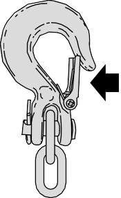
If the trailer safety chain hook has a latch, make sure the latch is fully closed.
Note: If you install the hook with the latch facing toward the rear of your vehicle, you may not be able to fully close the safety chain hook latch. If this occurs, install the hook with the latch facing toward the front of your vehicle.
|
|
 WARNING: Do not connect a trailer's hydraulic brake system directly to your vehicle's brake system. Your vehicle may not have enough braking power and your chances of having a collision greatly increase.
Electric brakes and manual, automatic or surge-type trailer brakes are safe if you install them properly and adjust them to the manufacturer's specifications. The trailer brakes must meet local and federal regulations.
Separate functioning brake systems are required for safe control of towed vehicles and trailers weighing more than 1500 lb (680 kg) when loaded.
291
(If Equipped)
|
Failure to follow this instruction could result in the loss of control of your vehicle, personal injury or death. |
 WARNING: The anti-lock brake system does not control the trailer brakes.
 WARNING: Use the integrated trailer brake controller to properly adjust the trailer brakes and check all connections before towing a trailer.
Note: The integrated Ford brake controller is compatible with trailers equipped with electric-actuated drum brakes and
electric-over hydraulic brake systems.
Note: The integrated Ford brake controller does not control hydraulic surge-style brakes.
E183395
When used properly, the trailer brake controller assists in smooth and effective trailer braking by powering the trailer’s electric or electric-over-hydraulic brakes with a proportional output based on the towing vehicle’s brake pressure.
You can adjust the amount of initial trailer brake output by selecting one of three settings through the message center.
Ford has tested the trailer brake controller to be compatible with several major brands of electric-over-hydraulic trailer brakes. Contact an authorized dealer for information on which brands you can use.
The controller user interface consists of the following:
A: + and - (Gain adjustment buttons): Pressing these buttons adjusts the controller's power output to the trailer brakes in 0.5 increments. You can increase the gain setting to 10.0 (maximum trailer braking) or decrease it to 0 (no trailer braking). Pressing and holding a button raises or lowers the setting continuously. The gain setting displays in the message center as follows: TBC GAIN = XX.X.
B: Manual control lever: Slide the control lever to the left to switch on the trailer's electric brakes independent of the tow vehicle's. See the following Procedure for adjusting gain section for instructions on proper use of this feature. If you use the manual control while the brake is also applied, the greater of the two inputs determines the power sent to the trailer brakes.
• Stop lamps: Using the manual control lever lights both the trailer brake lamps and your vehicle brake lamps.
Trailer brake control messages appear in the information display as follows:
Shows the current gain setting.
/ /: Displays when braking. The bars indicate the amount of power going to the trailer brakes.
• TRAILER CONNECTED: Displays when the system senses a correct trailer wiring connection.
• TRAILER DISCONNECTED: Displays when the system senses a trailer disconnection.
292
Choose either the electric option for trailers with electromagnetic drum brakes, or the electric over hydraulic option for trailers with these brake systems.
The trailer brake controller allows the user to customize how aggressively the trailer brakes engage. The default value is the low setting and is the recommended setting for most trailers. If your trailer's brakes require more initial voltage, or if you prefer more aggressive trailer braking, then select either the medium or the high setting.
Choose the low, medium or high setting for the required initial trailer brake output.
Note: Only perform this procedure in a traffic-free environment at speeds of approximately 20–25 mph (30–40 km/h).
The gain setting adjusts the trailer brake controller for the specific towing condition. You should change the setting as towing conditions change. Changes to towing conditions include trailer load, vehicle load, road conditions and weather.
The gain should be set to provide the maximum trailer braking assistance while making sure the trailer wheels do not lock when using the brakes. Locked trailer wheels may lead to trailer instability.
Note: An authorized dealer can diagnose the trailer brake controller to determine exactly which trailer fault has occurred.
However, your Ford warranty does not cover this diagnosis if the fault is with the trailer.
Displays in response to faults sensed by the trailer brake controller, accompanied by a single tone. If this message appears, contact an authorized dealer as soon as possible for diagnosis and repair. The controller may still function, but with degraded performance.
Displays when there is a short circuit on the electric brake output wire.
293
If this message displays, with no trailer connected, the problem is with your vehicle wiring or trailer brake controller. Contact an authorized dealer.
If the message only displays with a trailer connected, the problem is with the trailer wiring. Consult your trailer dealer for assistance. This can be a short to ground (such as a chaffed wire), short to voltage (such as a pulled pin on trailer emergency breakaway battery) or the trailer brakes may be drawing too much current.
Note: Do not attempt removal of the trailer brake controller without consulting the Workshop Manual. Damage to the unit may result.
• Adjust gain setting before using the trailer brake controller.
• Adjust gain setting, using the procedure above, whenever road, weather, trailer or vehicle loading conditions change from when the gain was initially set.
• Only use the manual control lever for proper adjustment of the gain during trailer setup. Misuse, such as application during trailer sway, could cause instability of trailer or tow vehicle.
• Avoid towing in adverse weather conditions. The trailer brake controller does not provide anti-lock control of the trailer wheels. Trailer wheels can lock up on slippery surfaces, resulting in reduced stability of trailer and tow vehicle.
• The trailer brake controller is equipped with a feature that reduces output at vehicle speeds below 11 mph (18 km/h) so trailer and vehicle braking is not jerky or harsh. This feature is only active when applying the brakes using your vehicle's brake pedal, not the controller.
• The controller interacts with the brake control system and powertrain control system of your vehicle to provide the best performance on different road conditions.
• Your vehicle's brake system and the trailer brake system work independently of each other. Changing the gain setting on the controller does not affect the operation of your vehicle's brakes.
• When you switch the engine off, the controller output is disabled and the display and module shut down.
|
|
 WARNING: Never connect any trailer lamp wiring to the vehicle's tail lamp wiring; this may damage the electrical system resulting in fire. Contact your authorized dealer as soon as possible for assistance in proper trailer tow wiring installation. Additional electrical equipment may be required.
Trailer lamps are required on most towed vehicles. Make sure all running lights, brake lights, turn signals and hazard lights are working.
Practice turning, stopping and backing up to get the feel of your vehicle-trailer combination before starting on a trip.
When turning, make wider turns so the trailer wheels clear curbs and other obstacles.
294
• Check your hitch, electrical connections and trailer wheel lug nuts thoroughly after you have traveled 50 mi (80 km).
• Do not drive faster than 70 mph (113 km/h) during the first 500 mi (800 km).
• Do not make full-throttle starts.
• When stopped in congested or heavy traffic during hot weather, place the gearshift in park (P) to aid engine and transmission cooling and to help A/C performance.
• Turn off the speed control with heavy loads or in hilly terrain. The speed control may turn off automatically when you are towing on long, steep grades.
• Shift to a lower gear when driving down a long or steep hill. Do not apply the brakes continuously, as they may overheat and become less effective.
• If your transmission is equipped with a Grade Assist or Tow/Haul feature, use this feature when towing. This provides engine braking and helps eliminate excessive transmission shifting for optimum fuel economy and transmission cooling.
• If your vehicle is equipped with Adaptive Steering and you have enabled Tow/Haul, the Adaptive Steering system adjusts the steering response to match your vehicle’s load. The system reduces vehicle sensitivity to steering inputs at higher vehicle speeds while it maintains the ease of parking and maneuverability at low speeds.
• If your vehicle is equipped with AdvanceTrac with RSC, this system may turn on during typical cornering maneuvers with a heavily loaded trailer. This is normal. Turning the corner at a slower speed while towing may reduce this tendency.
• If you are towing a trailer frequently in hot weather, hilly conditions, at the gross combined weight rating (or any combination of these factors), consider refilling your rear axle with synthetic gear lubricant (if the axle is not already filled with it).
• Allow more distance for stopping with a trailer attached. Anticipate stops and brake gradually.
• Avoid parking on a grade. However, if you must park on a grade:
Your vehicle may be equipped with a temporary or conventional spare tire. A "temporary" spare tire is different in size (diameter or width), tread-type
(All-Season or All Terrain) or is from a different manufacturer than the road tires on your vehicle. Consult information on the tire label or Safety Compliance label for limitations when using.
Note: Disconnect the wiring to the trailer
before backing the trailer into the water.
Note: Reconnect the wiring to the trailer
after you remove the trailer from the water.
295
When backing down a ramp during boat launching or retrieval:
• Do not allow the static water level to rise above the bottom edge of the rear bumper.
• Do not allow waves to break higher than 6 in (15 cm) above the bottom edge of the rear bumper.
Exceeding these limits may allow water to enter vehicle components:
• Causing internal damage to the components.
• Affecting driveability, emissions, and reliability.
Replace the rear axle lubricant anytime the rear axle has been submerged in water. Water may have contaminated the rear axle lubricant, which is not normally checked or changed unless a leak is suspected or other axle repair is required.
|
|
 WARNING: If your vehicle has a steering wheel lock make sure the ignition is in the accessory or on position when being towed.
If your vehicle becomes inoperable (without access to wheel dollies,
car-hauling trailer, or flatbed transport vehicle), it can be flat-towed (all wheels on the ground, regardless of the powertrain and transmission configuration) under the following conditions:
• Your vehicle is facing forward for towing in a forward direction.
• Place the transmission in neutral (N). If you cannot move the transmission into neutral (N), you may need to override it. See Transmission (page 206).
• Maximum speed is 35 mph (56 km/h).
• Maximum distance is 50 mi (80 km).
|
|
 WARNING: If your vehicle has a steering wheel lock make sure the ignition is in the accessory or on position when being towed.
Note: Put your climate control system in recirculated air mode to prevent exhaust fumes from entering your vehicle. See Climate Control (page 145).
Follow these guidelines if you have a need for recreational towing, such as towing your vehicle behind a motorhome. We have designed these guidelines to prevent damage to your transmission.
Do not tow your vehicle with any wheels on the ground, as vehicle or transmission damage may occur. It is recommended to tow your vehicle with all four (4) wheels off the ground, such as when using a
car-hauling trailer. Otherwise, you cannot tow your vehicle.
296
Only tow a four-wheel drive vehicle that has an electronic-shift transfer case with all wheels on the ground. To do this, place the transfer case in its neutral position and engage the four-wheel-down towing feature.
Perform the steps in the following section after positioning your vehicle behind the tow vehicle and properly securing them together.
Note: Make sure you properly secure your vehicle to the tow vehicle.
2H.
Note: If completed successfully, the information display shows a message indicating that your vehicle is safe to tow with all wheels on the ground.
Note: If you do not see the message in the display, you must perform the procedure again from the beginning.
Note: You may hear an audible noise as the transfer case shifts into its neutral position. This is normal.
|
|
 WARNING: Do not disconnect the battery during recreational towing. It prevents the transfer case from shifting properly and may cause the vehicle to roll, even if the transmission is in park (P).
 WARNING: Shifting the transfer case to its neutral position for recreational towing may cause the vehicle to roll, even if the transmission is in park (P). It may injure the driver and others. Make sure you press the foot brake and the vehicle is in a secure, safe position when you shift to neutral (N).
Note: Failing to put the transfer case in its neutral position while towing with all four wheels on the ground will damage vehicle components.
297
Note: You can check four-wheel-down towing status at any time by opening the driver's door or turning the ignition to the accessory or on position and verifying a message displays in the cluster.
To exit four-wheel-down towing and return the transfer case to its 2H position:
(N) and into any other gear.
Note: If completed successfully, the 2H indicator light illuminates and a confirmation message displays in the instrument cluster.
Note: If the indicator light and message do not display, you must perform the procedure again from the beginning.
Note: You may hear an audible noise as the transfer case shifts out of its neutral position. This is normal.
Note: If a message displays in the instrument cluster stating there is a shift delay, transfer case gear tooth blockage may be present. See Resolving the Shift Delay Issue after this section.
If the instrument cluster displays a shift delay message, See Information Messages (page 128). You need to perform the following steps:
298
Download Manual