Load Carrying


Note: The system does not detect, warn or respond to potential collisions with vehicles to the rear or side of your vehicle.
Note: The system is active at speeds above approximately 5 mph (8 km/h).
Note: The system becomes unavailable if you disable the electronic stability control. See Using Stability Control (page 229).
E156130
The system is designed to alert the driver of certain collision risks. A radar detects if your vehicle is rapidly approaching another vehicle traveling in the same direction as yours.
When your vehicle rapidly approaches another vehicle, a red warning light illuminates and an audible warning tone sounds.
The brake support system assists the driver in reducing the collision speed by charging the brakes. If the risk of collision further increases after the warning light illuminates, the brake support prepares the brake system for rapid braking. This may be apparent to the driver. Brake support does not automatically apply the brakes. If you press the brake pedal, the system could apply additional braking up to maximum braking force, even if you lightly press the brake pedal.
You can use your information display control to adjust the system's sensitivity or to switch the system on or off. Your vehicle remembers the settings across key cycles. You may change the system sensitivity to any one of three possible settings. See General Information (page 112).
Note: We recommend that you switch the system off if you install a snow plow or similar object in such a way that it may block the radar sensor. Your vehicle remembers the selected setting across key cycles.

263
Note: If you perceive warnings being too frequent or disturbing, you can reduce the warning sensitivity, though the manufacturer recommends using the highest sensitivity setting where possible. Setting to a lower sensitivity would lead to fewer and later system warnings. See General Information (page 112).
E183741
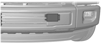
If a message regarding a blocked sensor appears in the information display, the radar signals from the sensor are obstructed. The sensors are behind a fascia cover near the driver side of the lower grille. When the sensors are obstructed, the system cannot detect a vehicle ahead and the system does not function. The following table lists possible causes and actions for when this message displays.
|
Cause |
Action |
|
The surface of the radar in the grille is dirty or obstructed in some way. |
Clean the grille surface in front of the radar or remove the object causing the obstruc- tion. |
|
The surface of the radar in the grille is clean but the message remains in the display. |
Wait a short time. It may take several minutes for the radar to detect that there are no obstructions. |
|
Heavy rain, spray, snow or fog is interfering with the radar signals. |
The system temporarily disables and reactivates a short time after the weather conditions improve. |
|
Swirling water, snow or ice on the surface of the road may interfere with the radar signals. |
The system temporarily disables and reactivates a short time after the weather conditions improve. |
Due to the nature of radar technology, there may be certain instances where vehicles do not provide a collision warning. These include:
• Stationary vehicles or vehicles moving below 6 mph (10 km/h).
• Pedestrians or objects in the roadway.
• Oncoming vehicles in the same lane.
• Severe weather conditions.
• Debris build-up on the grille near the headlamps.
264
• A short distance to the vehicle ahead.
• Large steering wheel and pedal movements.
If the front end of your vehicle is hit and damage occurs, the radar sensing zone may be altered causing missed or false collision warnings. See your authorized dealer to have your radar checked for proper coverage and operation.
265
Vehicle Loading - with and without a Trailer
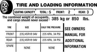
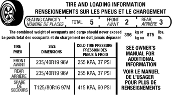
Before you load your vehicle, become familiar with the following terms for determining your vehicle’s weight rating, with or without a trailer, from the vehicle’s Tire and Loading Information label or Safety Compliance Certification label.
E198719
266
When towing, trailer tongue weight or king pin weight is also part of payload.
|
appropriate loading capacity of your vehicle can be limited either by volume capacity (how much space is available) or by payload capacity (how much weight the vehicle should carry). Once you have reached the maximum payload of your vehicle, do not add more cargo, even if there is space available. Overloading or improperly loading your vehicle can contribute to loss of vehicle control and vehicle rollover. |
 WARNING: The
GAWR (Gross Axle Weight Rating)
GAWR is the maximum allowable weight that a single axle (front or rear) can carry. These numbers are on the Safety Compliance Certification label. The label is located on the door hinge pillar, door-latch post, or the door edge that meets the door-latch post, next to the driver seating position.
The total load on each axle must never exceed its Gross Axle Weight Rating.
GVWR (Gross Vehicle Weight Rating)
GVWR is the maximum allowable weight of the fully loaded vehicle. This includes all options, equipment, passengers and cargo. It appears on the Safety Compliance Certification label.
The label is located on the door hinge pillar, door-latch post, or the door edge that meets the
door-latch post, next to the driver seating position.
The gross vehicle weight must never exceed the Gross Vehicle Weight Rating.
E198828
267
|
SafeWARNING: Exceeding the ty Compliance Certification label vehicle weight limits can adversely affect the performance and handling of your vehicle, cause vehicle damage and can result in the loss of control of your vehicle, serious personal injury or death. |
GCWR (Gross Combined Weight Rating)
GCWR is the maximum allowable weight of the vehicle and the loaded trailer, including all cargo and passengers, that the vehicle can handle without risking damage. (Important: The towing vehicle’s braking system is rated for operation at Gross Vehicle Weight Rating, not at Gross Combined Weight Rating.) Separate functional brakes should be used for safe control of towed vehicles and for trailers where the Gross Combined Weight of the towing vehicle plus the trailer exceed the Gross Vehicle Weight Rating of the towing vehicle.
The gross combined weight must never exceed the Gross Combined Weight Rating.

 Note: For trailer towing information refer to the RV and Trailer Towing Guide available at an authorized dealer.
|
the WARNING: Do not exceed GVWR or the GAWR specified on the certification label. repl WARNING: Do not use acement tires with lower load carrying capacities than the original tires because they may lower your vehicle's GVWR and GAWR limitations. Replacement tires with a higher limit than the original tires do not increase the GVWR and GAWR limitations. v WARNING: Exceeding any ehicle weight rating can adversely affect the performance and handling of your vehicle, cause vehicle damage and can result in the loss of control of your vehicle, serious personal injury or death. |
 Steps for determining the correct load limit:
1. Locate the statement "The combined weight of occupants and cargo should never exceed XXX kg or XXX lb." on your vehicle’s placard.
268
(1400-750 (5 x 150) = 650 lb.)
Helpful examples for calculating the available amount of cargo and luggage load capacity
1400-pound (635-kilogram) cargo and luggage capacity. You decide to go golfing. Is there enough load capacity to carry you, four of your friends and all the golf bags? You and four friends average 220 pounds (99 kilograms) each and the golf bags weigh approximately 30 pounds (13.5 kilograms) each. The calculation would be: 1400 - (5 x 220) - (5 x 30) = 1400 - 1100
- 150 = 150 pounds. Yes, you have enough load capacity in your vehicle to transport four friends and your golf bags. In metric units, the calculation would be: 635 kilograms - (5 x 99 kilograms) - (5 x 13.5 kilograms) = 635 - 495 -
67.5 = 72.5 kilograms.
Suppose your vehicle has a
1400-pound (635-kilogram) cargo and luggage capacity. You and one of your friends decide to pick up cement from the local home improvement store to finish that patio you have been planning for the past two years. Measuring the inside of the vehicle with the rear seat folded down, you have room for twelve 100-pound
(45-kilogram) bags of cement. Do you have enough load capacity to transport the cement to your home? If you and your friend each weigh 220 pounds (99 kilograms), the calculation would be: 1400 - (2 x 220) - (12 x 100) = 1400 - 440
269
900 = 60 pounds. Now you have the load capacity to transport the cement and your friend home. In metric units, the calculation would be: 635 kilograms - (2 x 99 kilograms) - (9 x 45 kilograms) = 635 - 198 - 405 = 32 kilograms.
The above calculations also assume that the loads are positioned in your vehicle in a manner that does not overload the front or the rear gross axle weight rating specified for your vehicle on the Safety Compliance Certification label.
Special Loading Instructions for Owners of Pick-up Trucks and Utility-type Vehicles

|
handle differently than unloaded vehicles. Take extra precautions, such as slower speeds and increased stopping distance, when driving a heavily loaded vehicle. |
BED RAMPS (IF EQUIPPED)
|
plate. Failure to follow this instruction could result in personal injury.
Failure to follow this instruction could result in personal injury. |
 WARNING: When sliding the ramp up or down, take care not to get your fingers or hands caught in the mechanism. Failure to follow this instruction could result in personal injury.
  WARNING: Make sure that you correctly install the ramp to the tailgate
 WARNING: Do not step or sit on the ramp when it is in the stowed position. Failure to follow this instruction could result in personal injury.
 WARNING: Only install the ramp within the prescribed ramp angles.
Note: The ramp maximum capacity is 800 lb (363 kg).
Note: Verify the ramp is on stable ground before usage.
Note: For loading and unloading equipment, your ramp should be set between 10 degrees upward and 26 degrees downward to avoid damage to the ramp claw and tailgate plate.
270
Note: When using your vehicle for off-road operation, remove the bed ramps from the vehicle and store them in a safe location away from your vehicle.
5. Slide the ramp claw onto the tailgate plate.
Note: You can use a smooth surface tool to rotate the stops.
E194383
6. Pull the location pin outward and extend the ramp until the pin is seated in the usage position, then set the ramp on even ground.
271
Note: Make sure the proper pin location has been applied for your bed size.
Note: Make sure you properly secure the locking cable. If the locking cable is unsecured, you may hear a rattling noise.
Note: The nut should be on the upper stud.
272
Download Manual