Wheels and Tires
Use only approved wheel and tire sizes, using other sizes could damage your vehicle. If you change the diameter of the tires from that fitted at the factory, the speedometer may not display the correct speed. Take your vehicle to an authorized dealer to have the system reprogrammed. If you intend to change the size of the wheels from that fitted by the manufacturer, you can check the suitability with an authorized dealer.
Additional information related to the functionality and maintenance of your tires can be found later in this chapter. See Tire Care (page 382).
The Ford recommended tire inflation pressures can be found on the Tire Label, which is located on the B-pillar or the edge of the driver's door. This information can also be found on the Safety Compliance Certification Label (affixed to either the door hinge pillar, door-latch post, or the door edge that meets the door last post; next to the driver’s seating position).
Ford strongly recommends maintaining these tire pressures at all times. Failure to follow the tire pressure recommendations can cause uneven treadwear patterns, reduced fuel economy, and adversely affect the way your vehicle handles.
Note: Check and set the tire pressure at the ambient temperature in which you are intending to drive your vehicle and when the tires are cold.
Note: Check your tire pressures at least once per month.
Set the pressure for your spare tire to the highest value given for your vehicle and tire size combination (if equipped).
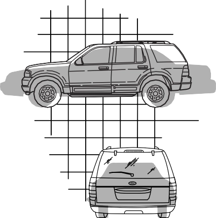
Utility vehicles have a significantly higher rollover rate than other types of vehicles.

 Vehicles with a higher center of gravity (utility and four-wheel drive vehicles) handle differently than
vehicles with a lower center of gravity (passenger cars). Avoid sharp turns, excessive speed and abrupt steering in these vehicles. Failure to drive cautiously increases the risk of losing control of your vehicle, vehicle rollover, personal injury and death.
 In a rollover crash, an unbelted person is significantly more likely to die than a person wearing a seatbelt.
 Do not become overconfident in the ability of four-wheel drive vehicles.
 Although a four-wheel drive vehicle may accelerate better than a two-wheel drive vehicle in low traction situations, it won't stop any faster than two-wheel drive vehicles. Always drive at a safe speed.
E145298
380
Utility vehicles and trucks handle differently than passenger cars in the various driving conditions that are encountered on streets, highways and
off-road. Utility vehicles and trucks are not designed for cornering at speeds as high as passenger cars any more than low-slung sports cars are designed to perform satisfactorily under off-road conditions.
Study your owner's manual and any supplements for specific information about equipment features, instructions for safe driving and additional precautions to reduce the risk of an accident or serious injury.
Do not become overconfident in the ability of four-wheel drive vehicles.
 Although a four-wheel drive vehicle may accelerate better than a two-wheel drive vehicle in low traction situations, it won't stop any faster than two-wheel drive vehicles. Always drive at a safe speed.
A vehicle equipped with four-wheel drive, when selected, has the ability to use all four wheels to power itself. This increases traction which may enable you to safely drive over terrain and road conditions that a conventional two-wheel drive vehicle cannot.
Power is supplied to all four wheels through a transfer case or power transfer unit. Four-wheel drive vehicles allow you to select different modes as necessary. For information on transfer case operation and shifting procedures, See Four-Wheel Drive (page 214). For information on transfer case maintenance, See Maintenance (page 328). You should become thoroughly familiar with this information before you operate your vehicle.
On some four-wheel drive vehicles, the initial shift from two-wheel to four-wheel drive when the vehicle is moving can cause a momentary clunk and ratcheting sound. These sounds are normal and are not cause for concern.
In four-wheel drive vehicles, the size of the spare tire relative to the remaining tires can have an effect on the 4x4 system. If there is a significant difference between the size of a spare and the remaining tires,
four-wheel drive functionality may be limited. See Using Four-Wheel Drive (page 214).
Sport utility vehicles and trucks can differ from some other vehicles in a few noticeable ways. Your vehicle may be:
E145299
381
Higher - to allow higher load carrying capacity and to allow it to travel over rough terrain without getting hung up or damaging underbody components.
Shorter - to give it the capability to approach inclines and drive over the crest of a hill without getting hung up or damaging underbody components. All other things held equal, a shorter wheelbase may make your vehicle quicker to respond to steering inputs than a vehicle with a longer wheelbase.
Narrower - to provide greater maneuverability in tight spaces, particularly in off-road use.
As a result of the above dimensional differences, Sport utility vehicles and trucks often have a higher center of gravity and a greater difference in center of gravity between the loaded and unloaded condition. These differences that make your vehicle so versatile also make it handle differently than an ordinary passenger car.
Information About Uniform Tire Quality Grading
E168583
E142542
These Tire Quality Grades are determined by standards that the United States Department of Transportation has set.
382
space-saver or temporary use spare tires, light truck or LT type tires, tires with nominal rim diameters of 10 to 12 inches or limited production tires as defined in Title 49 Code of Federal
 The traction grade assigned to this tire is based on
straight-ahead braking traction tests, and does not include acceleration, cornering, hydroplaning or peak traction characteristics.
Regulations Part 575.104 ©)(2).
U.S. Department of Transportation Tire quality grades: The U.S. Department of Transportation requires Ford Motor Company to give you the following information about tire grades exactly as the government has written it.
½) times as well on the government course as a tire graded 100. The relative performance of tires depends
The traction grades, from highest to lowest are AA, A, B, and C. The grades represent the tire’s ability to stop on wet pavement as measured under controlled conditions on specified government test surfaces of asphalt and concrete. A tire marked C may have poor traction performance.
Temperature A B C
The temperature grade for this tire is established for a
 tire that is properly inflated and not overloaded. Excessive speed, underinflation, or excessive loading, either separately or in combination, can cause heat buildup and possible tire failure.
upon the actual conditions of their
use, however, and may depart
significantly from the norm due to variations in driving habits, service practices, and differences in road characteristics and climate.
The temperature grades are A (the highest), B and C, representing the tire’s resistance to the generation of heat and its ability to dissipate heat when tested under controlled conditions on a specified indoor laboratory
383
Glossary of Tire Terminology
*Tire label: A label showing the original equipment tire sizes, recommended inflation pressure and the maximum weight the vehicle can carry.
*Tire Identification Number (TIN): A number on the sidewall of each tire providing information about the tire brand and manufacturing plant, tire size and date of manufacture. Also referred to as DOT code.
*Inflation pressure: A measure of the amount of air in a tire.
*Standard load: A class of
P-metric tires 35 psi (2.4 bar) and for Metric tires 36 psi (2.5 bar).
Increasing the inflation pressure beyond this pressure will not increase the tire’s load carrying capability.
*Extra load: A class of P-metric or Metric tires designed to carry a heavier maximum load at 42 psi (2.9 bar). Increasing the inflation pressure beyond this pressure will not increase the tire’s load carrying capability.
*kPa: Kilopascal, a metric unit of air pressure.
*PSI: Pounds per square inch, a standard unit of air pressure.
*Cold tire pressure: The tire pressure when the vehicle has been stationary and out of direct sunlight for an hour or more and prior to the vehicle being driven for 1 mile (1.6 kilometers).
*Recommended inflation pressure: The cold inflation pressure found on the Safety Compliance Certification Label (affixed to either the door hinge pillar, door-latch post, or the door edge that meets the door-latch post, next to the driver's seating position), or Tire Label located on the B-pillar or the edge of the driver's door.
384
*Bead area of the tire: Area of the tire next to the rim.
* Sidewall of the tire: Area between the bead area and the tread.
*Tread area of the tire: Area of the perimeter of the tire that contacts the road when mounted on the vehicle.
Information Contained on the Tire Sidewall
Both United States and Canada Federal regulations require tire manufacturers to place standardized information on the sidewall of all tires. This information identifies and describes the fundamental characteristics of the tire and also provides a U.S. DOT Tire Identification Number for safety standard certification and in case of a recall.
Information on P Type Tires
E142543
A. P: Indicates a tire, designated by the Tire and Rim Association, that may be used for service on cars, sport utility vehicles, minivans and light trucks. Note: If your tire size does not begin with a letter this may mean it is designated by either the European Tire and Rim Technical Organization or the Japan Tire Manufacturing Association.
385
Note: You may not find this information on all tires because it is not required by federal law.
Note: You may not find this information on all tires because it is not required by federal law.
|
Letter rating |
mph ( km/h) |
|
M |
81 (130) |
|
N |
87 (140) |
|
Q |
99 (159) |
|
R |
106 (171) |
|
S |
112 (180) |
|
T |
118 (190) |
|
U |
124 (200) |
|
H |
130 (210) |
|
V |
149 (240) |
|
W |
168 (270) |
|
Y |
186 (299) |
Note: For tires with a maximum speed capability over 149 mph (240 km/h), tire manufacturers sometimes use the letters ZR. For those with a maximum speed capability over 186 mph (299 km/h), tire manufacturers always use the letters ZR.
386
AT: All Terrain, or
AS: All Season.
door-latch post, next to the driver's seating position), or Tire Label located on the B-pillar or the edge of the driver's door.
*Treadwear The treadwear grade is a comparative rating based on the wear rate of the tire when tested under controlled conditions on a specified government test course. For example, a tire graded 150 would wear 1½ times as well on the government course as a tire graded 100.
*Traction: The traction grades, from highest to lowest are AA, A, B, and C. The grades represent the tire's ability to stop on wet pavement as measured under controlled conditions on specified government test surfaces of asphalt and concrete. A tire marked C may have poor traction performance.
*Temperature: The temperature grades are A (the highest), B and C, representing the tire's resistance to the generation of heat and its ability to dissipate heat when tested under controlled conditions on a specified indoor laboratory test wheel.
door-latch post, or the door edge
387
The tire suppliers may have additional markings, notes or warnings such as standard load or radial tubeless.
Additional Information Contained on the Tire Sidewall for LT Type Tires
Note: Tire Quality Grades do not apply to this type of tire.
Note: The temporary tire size for your vehicle may be different from this example. Tire Quality Grades do not apply to this type of tire.
LT type tires have some additional information beyond those of P type tires. These differences are described below.
388
E142545
R: Indicates a radial type tire.
Location of the Tire Label
You will find a Tire Label containing tire inflation pressure by tire size and other important information located on the B-Pillar or the edge of the driver's door.
Inflating Your Tires
Safe operation of your vehicle requires that your tires are properly inflated. Remember that a tire can lose up to half of its air pressure without appearing flat.
Every day before you drive, check your tires. If one looks lower than the others, use a tire gauge to check pressure of all tires and adjust if required.
At least once a month and before long trips, inspect each tire and check the tire pressure with a tire gauge (including spare, if equipped). Inflate all tires to the inflation pressure recommended by Ford Motor Company.
389
Use the recommended cold inflation pressure for optimum tire performance and wear.
Under-inflation or over-inflation may cause uneven treadwear patterns.
 Under-inflation is the most common cause of tire failures
and may result in severe tire cracking, tread separation or blowout, with unexpected loss of vehicle control and increased risk of injury. Under-inflation increases sidewall flexing and rolling resistance, resulting in heat buildup and internal damage to the tire. It also may result in unnecessary tire stress, irregular wear, loss of vehicle control and accidents. A tire can lose up to half of its air pressure and not appear to be flat!
Always inflate your tires to the Ford recommended inflation pressure even if it is less than the maximum inflation pressure information found on the tire. The Ford recommended tire inflation pressure is found on the Safety Compliance Certification Label or
Tire Label (affixed to either the door hinge pillar, door-latch post, or the door edge that meets the door-latch post, next to the driver's seating position), or Tire Label located on the B-pillar or the edge of the driver's door.
Failure to follow the tire pressure recommendations can cause uneven treadwear patterns and adversely affect the way your vehicle handles.
Note: Do not reduce tire pressure to change the ride characteristics of the vehicle. If you do not maintain the inflation pressure at the levels specified by Ford, your vehicle may experience a condition known as shimmy. Shimmy is a severe vibration and oscillation in the steering wheel after the vehicle travels over a bump or dip in the road that does not dampen out by itself. Shimmy may result from significant under-inflation of the tires, improper tires (load range, size, or type), or vehicle modifications such as lift-kits. In the event that your vehicle experiences shimmy, you should slowly reduce speed by either lifting off the accelerator pedal or lightly applying the brakes. The shimmy will cease as the vehicle speed decreases.
Maximum Inflation Pressure is the tire manufacturer's maximum permissible pressure and the pressure at which the maximum load can be carried by the tire. This pressure is normally higher than
390
When weather temperature changes occur, tire inflation pressures also change. A 10°F (6°C) temperature drop can cause a corresponding drop of 1 psi (7 kPa) in inflation pressure. Check your tire pressures frequently and adjust them to the proper pressure which can be found on the Safety Compliance Certification Label or Tire Label.
To check the pressure in your tire(s):
Note: If you are checking tire pressure when the tire is hot, (for example, driven more than 1 mile [1.6 kilometers]), never bleed or reduce air pressure. The tires are hot from driving and it is normal for pressures to increase above recommended cold pressures. A hot tire at or below recommended cold inflation pressure could be significantly under-inflated.
Note: If you have to drive a distance to get air for your tire(s), check and record the tire pressure first and add the appropriate air pressure when you get to the pump. It is normal for tires to heat up and the air pressure inside to go up as you drive.
Note: If you overfill the tire, release air by pressing on the metal stem in the center of the valve. Then recheck the pressure with your tire gauge.
391
Note: Some spare tires operate at a higher inflation pressure than the other tires. For T type mini-spare tires, (see the Dissimilar spare wheel and tire assembly information for a description. Store and maintain at 60 psi (4.15 bar). For full-size and dissimilar spare tires, see the Dissimilar spare wheel and tire assembly information for a description. Store and maintain at the higher of the front and rear inflation pressure as shown on the Safety Compliance Certification Label or Tire Label.
All tires with Steel Carcass Plies (if equipped):
This type of tire utilizes steel cords in the sidewalls. As such, they cannot be treated like normal light truck tires. Tire service, including adjusting tire pressure, must be performed by personnel trained, supervised and equipped according to Federal Occupational Safety and Health Administration regulations. For example, during any procedure involving tire inflation, the technician or individual must utilize a remote inflation device, and ensure that all persons are clear of the trajectory area.
 Always inflate steel carcass tires with a remote air fill with
the person inflating standing at a minimum of 12 ft (3.66 m) away from the wheel and tire assembly.
 An inflated tire and rim can be very dangerous if
improperly used, serviced or maintained. To reduce the risk of serious injury, never attempt to
re-inflate a tire which has been run flat or seriously under-inflated without first removing the tire from the wheel assembly for inspection. Do not attempt to add air to tires or replace tires or wheels without first taking precautions to protect persons and property.
392
E161437
Inspect the tire sidewalls for cracking, cuts, bruises and other signs of damage or excessive wear. If internal damage to the tire is suspected, have the tire demounted and inspected in case
it needs to be repaired or replaced. For your safety, tires that are damaged or show signs of excessive wear should not be used because they are more likely to blow out or fail.
Improper or inadequate vehicle maintenance can cause tires to wear abnormally. Inspect all your tires, including the spare, frequently, and replace them if one or more of the following conditions exist:
393
Age
E142546
When the tire tread wears down to the same height as these wear bars, the tire is worn out and must be replaced.
Damage
Periodically inspect the tire treads and sidewalls for damage (such as bulges in the tread or sidewalls, cracks in the tread groove and separation in the tread or sidewall). If damage is observed
WARNINGS
Tires degrade over time depending on many factors
such as weather, storage conditions, and conditions of use (load, speed, inflation pressure) the tires experience throughout their lives.
 In general, tires should be replaced after six years
regardless of tread wear or even if they have not been used.
However, heat caused by hot climates or frequent high-load conditions can accelerate the aging process and may require you to replace tires more frequently.
 You should replace your spare tire when you replace
the road tires or after six years due to aging even if it has not been used.
394
This begins with the letters DOT and indicates that the tire meets all federal standards. The next two numbers or letters are the plant code designating where it was manufactured, the next two are the tire size code and the last four numbers represent the week and year the tire was built. For example, the numbers 317 mean the 31st week of 1997. After 2000 the numbers go to four digits. For example, 2501 means the 25th week of 2001. The numbers in between are identification codes used for traceability. This information is used to contact customers if a tire defect requires a recall.
Tire Replacement Requirements
Your vehicle is equipped with tires designed to provide a safe ride and handling capability.
 Only use replacement tires and wheels that are the same
size, load index, speed rating and type (such as P-metric versus
LT-metric or all-season versus all-terrain) as those originally provided by Ford. The
recommended tire and wheel size may be found on either the Safety Compliance Certification Label (affixed to either the door hinge pillar, door-latch post, or the door edge that meets the door-latch post, next to the driver’s seating position), or the Tire Label which is located on the B-Pillar or edge of the driver’s door. If this information is not found on these labels, then you should contact your authorized dealer as soon as possible. Use of any tire or wheel not recommended by Ford can affect the safety and performance of your vehicle, which could result in an increased risk of loss of vehicle control, vehicle rollover, personal injury and death.
 To reduce the risk of serious injury, when mounting
replacement tires and wheels, you should not exceed the maximum pressure indicated on the sidewall of the tire to set the beads without additional precautions listed below. If the beads do not seat at the maximum pressure indicated, re-lubricate and try again.
395
 For a mounting pressure more than 20 psi (1.38 bar)
greater than the maximum pressure, a Ford dealer or other tire service professional should do the mounting.
 Always inflate steel carcass tires with a remote air fill with
the person inflating standing at a minimum of 12 ft (3.66 m) away from the wheel and tire assembly.
Important: Remember to replace the wheel valve stems when the road tires are replaced on your vehicle.
The two front tires or two rear tires should generally be replaced as a pair.
The tire pressure sensors mounted in the wheels are not designed to be used in aftermarket wheels.
The use of wheels or tires not recommended by Ford Motor Company may affect the operation of your tire pressure monitoring system.
If the tire pressure monitoring system indicator is flashing, the system is malfunctioning. Your replacement tire might be incompatible with your tire pressure monitoring system, or some component of the system may be damaged.
Replacing a Tire That is Greenhouse Gas Certified
The tires installed on this vehicle at the factory as original equipment are certified for Greenhouse Gas and Fuel Efficiency regulations.
Replacement tires must be of equal or lower rolling resistance level (TRRL or Crr). Consult with your tire supplier(s) for appropriate replacement tires.
396
WARNINGS
rapidly spin the tires; spinning the tires can tear the tire and cause an explosion. A tire can explode in as little as three to five seconds.
 Do not spin the wheels at over 34 mph (55 km/h). The
tires may fail and injure a passenger or bystander.
Driving habits have a great deal to do with your tire mileage and safety.
*Observe posted speed limits.
*Avoid fast starts, stops and turns.
*Avoid potholes and objects on the road.
*Do not run over curbs or hit the tire against a curb when parking.
Highway Hazards
No matter how carefully you drive there’s always the possibility that you may eventually have a flat tire on the highway. Drive slowly to the closest safe area out of traffic.
This may further damage the flat tire, but your safety is more important.
If you feel a sudden vibration or ride disturbance while driving, or you suspect your tire or vehicle has been damaged, immediately reduce your speed. Drive with caution until you can safely pull off the road. Stop and inspect the tires for damage. If a tire is
under-inflated or damaged, deflate it, remove wheel and replace it with your spare tire and wheel. If you cannot detect a cause, have the vehicle towed to the nearest repair facility or tire dealer to have the vehicle inspected.
Tire and Wheel Alignment
A bad jolt from hitting a curb or pothole can cause the front end of your vehicle to become misaligned or cause damage to your tires. If your vehicle seems to pull to one side when you’re driving, the wheels may be out of alignment. Have an authorized dealer check the wheel alignment periodically.
Wheel misalignment in the front or the rear can cause uneven and rapid treadwear of your tires and should be corrected by an authorized dealer. Front-wheel drive vehicles and those with an independent rear suspension may require alignment of all four wheels.
The tires should also be balanced periodically. An unbalanced tire and wheel assembly may result in irregular tire wear.
397
front and rear tires and the vehicle has a tire pressure monitoring system, then you need to update the settings for the system sensors. Always perform the system reset procedure after tire rotation. If you do not reset the system, it may not provide a low tire pressure warning when necessary.
Note: If your tires show uneven wear ask an authorized dealer to check for and correct any wheel misalignment, tire imbalance or mechanical problem involved before tire rotation.
Note: Your vehicle may be equipped with a dissimilar spare wheel and tire assembly. A dissimilar spare wheel and tire assembly is defined as a spare wheel and tire assembly that is different in brand, size or appearance from the road tires and wheels. If you have a dissimilar spare wheel and tire assembly it is intended for temporary use only and should not be used in a tire rotation.
Note: After having your tires rotated, inflation pressure must be checked and adjusted to the vehicle requirements.
Rotating your tires at the recommended interval (as indicated in the Scheduled Maintenance chapter) will help your tires wear more evenly, providing better tire performance and longer tire life. Sometime irregular tire wear can be corrected by rotating the tires.
Rear-wheel drive vehicles and four-wheel drive vehicles (front tires at left of diagram).
398
E166988
If your vehicle is equipped with dual rear wheels it is recommended that the front and rear tires (in pairs) be rotated only side to side. We do not recommend splitting up the dual rear wheels. Rotate them side to side as a set. After tire rotation, inflation pressures must be adjusted for the tires new positions in accordance with vehicle requirements.
E227387
Note: When installing 17-inch dual rear wheels, align the valve stems facing each other.
399
Snow tires must be the same size, load index, speed rating as those originally provided by Ford. Use of
any tire or wheel not recommended by Ford can affect the safety and performance of your vehicle, which could result in an increased risk of loss of vehicle control, vehicle rollover, personal injury and death. Additionally, the use of
non-recommended tires and wheels could cause steering, suspension, axle, transfer case or power transfer unit failure.
Note: Do not use snow chains on vehicles with 20 inch wheels and tires.
The tires on your vehicle have all-weather treads to provide traction in rain and snow. However, in some climates, you may need to use snow tires and cables. If you need to use cables, it is recommended that steel wheels (of the same size and specifications) be used, as cables may chip aluminum wheels.
Note: The suspension insulation and bumpers will help prevent vehicle damage. Do not remove these components from your vehicle when using snow tires and chains.
Follow these guidelines when using snow tires and chains:
If possible, avoid fully loading your vehicle
Use only SAE Class S chains.
Install chains securely, verifying that the chains do not touch any wiring, brake lines or fuel lines.
Drive cautiously. If you hear the chains rub or bang against your vehicle, stop and retighten the chains. If this does not work, remove the chains to prevent damage to your vehicle.
Remove the tire chains when they are no longer needed. Do not use tire chains on dry roads.
If you have any questions regarding snow chains or cables, please contact your authorized dealer.
The tire pressure monitoring system is not a substitute for manually checking tire pressures. You should
periodically check tire pressures using a pressure gauge. Failure to correctly maintain tire pressures could increase the risk of tire failure, loss of control, vehicle rollover and personal injury.
Each tire, including the spare (if provided), should be checked monthly when cold and inflated
to the inflation pressure recommended by the vehicle manufacturer on the vehicle placard or tire inflation pressure label. (If your vehicle has tires of a different size than the size indicated on the vehicle placard or tire inflation pressure label, you should determine the proper tire inflation pressure for those tires.)
400
As an added safety feature, your vehicle has been equipped with a Tire Pressure Monitoring System (TPMS) that illuminates a low tire pressure telltale when one or more of your tires is significantly under-inflated. Accordingly, when the low tire pressure telltale illuminates, you should stop and check your tires as soon as possible, and inflate them to the proper pressure. Driving on a significantly under-inflated tire causes the tire to overheat and can lead to tire failure. Under-inflation also reduces fuel efficiency and tire tread life, and may affect the vehicle’s handling and stopping ability.
Please note that the TPMS is not a substitute for proper tire maintenance, and it is the driver’s responsibility to maintain correct tire pressure, even if under-inflation has not reached the level to trigger illumination of the TPMS low tire pressure telltale.
Your vehicle has also been equipped with a TPMS malfunction indicator to indicate when the system is not operating properly. The TPMS malfunction indicator is combined with the low tire pressure telltale. When the system detects a malfunction, the telltale will flash for approximately one minute and then remain continuously illuminated. This sequence will continue upon subsequent vehicle start-ups as long as the malfunction exists.
When the malfunction indicator is illuminated, the system may not be able to detect or signal low tire pressure as intended. TPMS malfunctions may occur for a variety of reasons, including the installation of replacement or alternate tires or wheels on the vehicle that prevent the TPMS from functioning properly.
Always check the TPMS malfunction telltale after replacing one or more tires or wheels on your vehicle to ensure that the replacement or alternate tires and wheels allow the TPMS to continue to function properly.
This device complies with Part 15 of the FCC Rules and with Industry Canada license-exempt RSS standard(s).
Operation is subject to the following two conditions:
Note: Each road tire is equipped with a tire pressure sensor located inside the wheel and tire assembly cavity. The pressure sensor is attached to the valve stem. The pressure sensor is covered by the tire and is not visible unless the tire is removed. Take care when changing the tire to avoid damaging the sensor.
You should always have your tires serviced by an authorized dealer.
Check the tire pressure periodically (at least monthly) using an accurate tire gauge. See Inflating Your Tires in this chapter.
401
Single Rear Wheel
Dual Rear Wheel
The tire pressure monitoring system measures pressure in your road tires and sends the tire pressure readings to your vehicle. The low tire pressure warning light will turn on if the tire pressure is significantly low. Once the light is illuminated, one or more of your tires are under-inflated and needs to be inflated to the manufacturer’s recommended tire pressure. Even if the light turns on and a short time later turns off, your tire pressure still needs to be checked.
When one of your road tires needs to be replaced with the temporary spare, the system will continue to identify an issue to remind you that the damaged road wheel and tire assembly needs to be repaired and put back on your vehicle.
To restore the full function of the tire pressure monitoring system, have the damaged road wheel and tire assembly repaired and remounted on your vehicle.
The main function of the tire pressure monitoring system is to warn you when your tires need air. It can also warn you in the event the system is no longer capable of functioning as intended. See the following chart for information concerning your tire pressure monitoring system:
402
|
Low tire pressure warning light |
Possible cause |
Customer action required |
|
Solid warning light |
Tire under inflated |
Make sure tires are at the proper pres- sure. See Inflating your tires in this chapter. After inflating your tires to the manufacturer’s recommended pressure as shown on the Tire Label (located on the edge of driver’s door or the B-Pillar), the vehicle must be driven for at least two minutes over 20 mph (32 km/h) before the light turns off. |
|
Spare tire in use |
Repair the damaged road wheel and tire assembly and reinstall it on the vehicle to restore system function. For a description on how the system functions, see When your temporary spare tire is installed in this section. |
|
|
Tire pressure monitoring system malfunction |
If the tires are properly inflated and the spare tire is not in use but the light remains on, contact your authorized dealer as soon as possible. |
|
|
Tire rotation without sensor training |
On vehicles with different front and rear tire pressures, the system must be retrained following every tire rotation. See Tire Care (page 382). |
|
|
Flashing warning light |
Spare tire in use |
Repair the damaged road wheel and tire assembly and reinstall it on the vehicle to restore system function. For a description on how the system functions, see When your temporary spare tire is installed in this section. |
|
Tire pressure monitoring system malfunction |
If the tires are properly inflated and the spare tire is not in use but the light remains on, contact your authorized dealer as soon as possible. |
403
When putting air into your tires (such as at a gas station or in your garage), the tire pressure monitoring system may not respond immediately to the air added to your tires.
It may take up to two minutes of driving over 20 mph (32 km/h) for the light to turn off after you have filled your tires to the recommended inflation pressure.
The tire pressure monitoring system monitors tire pressure in each pneumatic tire. While driving in a normal manner, a typical passenger tire inflation pressure may increase about 2 to 4 psi (14 to 28 kPa) from a cold start situation. If the vehicle is stationary overnight with the outside temperature significantly lower than the daytime temperature, the tire pressure may decrease about 3 psi (21 kPa) for a drop of 30°F (17°C) in ambient temperature. This lower pressure value may be detected by the tire pressure monitoring system as being significantly lower than the recommended inflation pressure and activate the system warning light for low tire pressure.
If the low tire pressure warning light is on, visually check each tire to verify that no tire is flat. If one or more tires are flat, repair as necessary. Check the air pressure in the road tires. If any tire is under-inflated, carefully drive the vehicle to the nearest location where air can be added to the tires. Inflate all the tires to the recommended inflation pressure.
WARNING
 To determine the required pressure(s) for your vehicle, see the Safety Compliance Certification
Label (on the door hinge pillar, door-latch post or the door edge that meets the door-latch post, next to the driver seat) or the Tire Label on the B-Pillar or the edge of the driver door.
Note: You need to perform the tire pressure monitoring system reset procedure after each tire rotation.
To provide the vehicle's load carrying capability, some vehicles require different recommended tire pressures in the front tires as compared to the rear tires. The tire pressure monitoring system equipped on these vehicles is designed to illuminate the low tire pressure warning light at two different pressures; one for the front tires and one for the rear tires.
Since tires need to be rotated to provide consistent performance and maximum tire life, the tire pressure monitoring system needs to know when the tires are rotated to determine which set of tires are on the front and which are on the rear. With this information, the system can detect and properly warn of low tire pressures.
System reset tips:
404
Read the entire procedure before attempting.
then park in a safe location where you can easily get to all four tires and have access to an air pump.
2. If after repeated attempts to enter the reset mode, the horn does not sound, the system indicator does not flash and no message is shown in the information display, seek service from your authorized dealer.
Note: The single horn chirp confirms that the sensor identification code has been learned by the module for this position. If a double horn is heard, the reset procedure was unsuccessful, and you must repeat it.
405
11. Set all four tires to the recommended air pressure as indicated on the Safety Compliance Certification Label (affixed to either the door hinge pillar, door-latch post, or the door edge that meets the door-latch post, next to the driver's seating position) or Tire Label located on the B-Pillar or the edge of the driver's door.
For further information see Understanding Your Tire Pressure Monitoring System and refer to Dual Rear Wheel, earlier in this section.
Read the entire procedure before attempting.
then park in a safe location where you can easily get to all six tires and have access to an air pump.
2. If after repeated attempts to enter the reset mode, the horn does not sound, the system indicator does not flash and no message is shown in the information display, seek service from your authorized dealer.
Note: The single horn chirp confirms that the sensor identification code has been learned by the module for this position. If a double horn is heard, the reset procedure was unsuccessful, and you must repeat it.
406
Trailer Tire Pressure Monitoring System (If Equipped)
Note: Additional equipment may be required for your vehicle to support trailer tire pressure monitoring. See your authorized dealer for more information.
Note: The trailer tire pressure monitoring system is not a substitute for proper tire maintenance. It is your responsibility to maintain correct tire pressures at all times.
Note: If a trailer tire is repaired, replaced or broken down for service, the screw and valve on the trailer tire pressure sensor should be replaced. See your authorized dealer for details.
The trailer tire pressure monitoring system is an added safety feature that allows you to view your trailer tire pressures through the information display. See General Information (page 113). Tire pressure sensors are mounted into each tire on your trailer. The sensors send a message to your vehicle indicating the current trailer tire pressure.
If the trailer tire pressure monitoring system detects that a tire is low, a warning message appears in the information display. The trailer tire pressure status screen in the information display highlights the tire with a low pressure.
The main function of the trailer tire pressure monitoring system is to warn you when your trailer tires need air. It can also warn you in the event the system is no longer capable of functioning as intended. See Information Messages (page 129).
If you have replaced a trailer tire with a new or spare tire, a warning message appears and pressure readings are no longer displayed for that tire.
To restore the full function of the trailer tire pressure monitoring system:
Note: You need to perform the tire pressure monitoring system reset procedure after each tire rotation, or when a new trailer tire pressure sensor is installed into a trailer tire.
407
The trailer tire pressure monitoring system can be reset through the menu in the information display. See General Information (page 113). Performing the trailer setup process also resets the trailer tire pressure monitoring system.
If the tire pressure monitor sensor becomes damaged it may not function.
Failure to follow these guidelines could result in an increased risk of loss of vehicle control, injury or death.
 If you have a dissimilar spare wheel and tire, then it is intended for temporary use only. This means that if you need to use it, you should replace it as soon as possible with a road wheel and tire assembly that
is the same size and type as the road tires
Note: If your vehicle is equipped with the tire pressure monitoring system, the indicator light illuminates when the spare tire is in use. To restore the full function of the monitoring system, all road wheels equipped with tire pressure monitoring sensors must be mounted on the vehicle.
Note: You should only use tire sealants in roadside emergencies as they may cause damage to the tire pressure monitoring system sensor.
If you get a flat tire when driving, do not apply the brake heavily. Instead, gradually decrease your speed. Hold the steering wheel firmly and slowly move to a safe place on the side of the road.
If your vehicle is equipped with the tire pressure monitoring system, have a flat serviced by an authorized dealer in order to prevent damage to the system sensors. See Tire Pressure Monitoring System (page 400). Replace the spare tire with a road tire as soon as possible. During repairing or replacing of the flat tire, have the authorized dealer inspect the system sensor for damage.
and wheels that were originally provided by Ford. If the dissimilar spare tire or wheel is damaged, it should be replaced rather than repaired.
A dissimilar spare wheel and tire assembly is defined as a spare wheel and tire assembly that is different in brand, size or appearance from the road tires and wheels.
When driving with the full-size dissimilar spare wheel and tire assembly, do not:
Exceed 70 mph (113 km/h).
Use more than one dissimilar spare wheel and tire assembly at a time.
Use snow chains on the end of the vehicle with the dissimilar spare wheel and tire assembly.
When driving with the full-size dissimilar spare wheel and tire assembly, it is recommended that you do not:
Exceed 50 mph (80 km/h) in 4WD.
Engage 4WD unless the vehicle is stationary.
Use 4WD on dry pavement.
408
The usage of a full-size dissimilar spare wheel and tire assembly can lead to impairment of the following:
When driving with the full-size dissimilar spare wheel and tire assembly additional caution should be given to:
Drive cautiously when using a full-size dissimilar spare wheel and tire assembly and seek service as soon as possible.
If your vehicle is equipped with a spare tire, jack and associated tools, see the following table for their locations:
|
Tool |
Location |
|
Spare tire - pick-up trucks only |
Under the vehicle, just forward of the rear bumper. |
|
Jack |
Fastened to the floor pan behind the rear- most seat on the passenger side. |
|
Jack handle, lug wrench, lug wrench exten- sion - only available on dual rear wheel vehicles and wheel chock - only available on single rear wheel vehicles equipped with a diesel engine. |
Regular Cab: Fastened to floor behind the driver seat. Super Cab and Crew Cab: Fastened to the floor under the rear seat on the driver's side. |
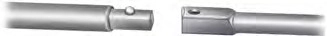
The following tools are required to remove the spare tire:
E162795
409
One handle extension and two typical extensions. To assemble, align the button with the hole and slide the parts together.
To disconnect, press the button and pull apart.
One wheel nut wrench. Slide over the square end of the jack handle.
E162797
E162800
 When one of the front wheels is off the ground, the transmission alone will not prevent the vehicle from
moving or slipping off the jack, even if the transmission is in park (P).
E227181
410
 To help prevent your vehicle from moving when changing a wheel, shift the transmission into park (P), set
the parking brake and use an appropriate block or wheel chock to secure the wheel diagonally opposite to the wheel being changed. For example, when changing the front left wheel, place an appropriate block or wheel chock on the right rear wheel.
 Do not get under a vehicle that is only supported by a vehicle jack.
 Do not attempt to change a tire on the side of the vehicle close to moving traffic. Pull far enough off the
road to avoid the danger of being hit when operating the jack or changing the wheel.
 Always use the jack provided as original equipment with your vehicle.
If using a jack other than the one provided, make sure the jack capacity is adequate for the vehicle weight, including any vehicle cargo or modifications. If you are unsure if the jack capacity is adequate, contact the authorized dealer.
 Only use the spare wheel carrier to stow the wheel provided with your vehicle. Other wheel sizes could
cause the spare wheel carrier to fail if it does not fit securely or is too heavy.
Note: Do not use impact tools or power tools operating at over 200 RPM on the spare wheel carrier winch, which may cause it to malfunction and prevent a secure fit. Override the winch at least three times (there is an audible click each time) to make sure the wheel and tire fit securely.
Note: Passengers should not remain in the vehicle when the vehicle is being jacked.
Park on a level surface, set the parking brake and activate the hazard flashers.
E142551
Note: Lock the manual hub on the wheel if the vehicle is a 4x4.
Note: For vehicles with dual rear wheels, insert the lug wrench extension into the lug wrench to reach the lug nuts.
411
E162802 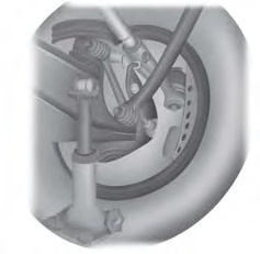
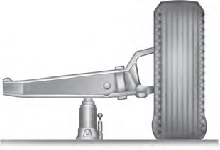
Front (4x2)
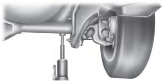
Front driver side (4x4)
Note: Make sure the jack fits onto the flat area on the outboard side of the differential.
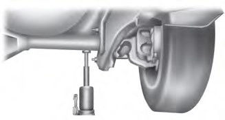
Front passenger side (4x4)
Note: View shown from the rear of the vehicle to clearly identify the jack point. Place the jack directly under the axle.
412
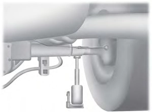
Rear
Note: Jack at the specified locations to avoid damage to the vehicle.
1
4 3
E162811
E161441 2
8-lug nut torque sequence
the wheel is completely off the ground and high enough to install the spare tire.
10 1
3 8
5 6
rear wheel vehicles. If you are replacing an inboard rear tire on dual rear wheel vehicles, the valve stem must be facing outward. If you are replacing the outboard wheel, the valve stem must be facing inward. Reinstall the lug nuts until the wheel is snug against the hub. Do not fully tighten the lug nuts until the wheel has been lowered.
7 4
E169375 2 9
10-lug nut torque sequence
413
When installing the wheel center ornaments, make sure that the ornament retention towers on the back side of the ornament are aligned with the studs or lug nuts. The retention towers are designed to be installed over the studs or nuts and retain to the flange on the lug nut.
If the ornament retention towers are aligned between the studs or lug nuts, the ornament is improperly installed. This improper installation may appear and sound correct, but does not keep the ornament on the vehicle. Ornaments improperly installed in this manner, fall off or become loose with minimal force or impact.
E162813
Front (4x2): F-350 dual rear wheel
Note: Place the jack directly under the I-beam.
Front driver side (4x4): F-350 dual rear wheel
Note: Make sure the jack fits onto the flat area on the outboard side of the differential housing.
414
E162815
Front passenger side (4x4): F-350 dual rear wheel
Note: View shown from the rear of the vehicle to clearly identify the jack point.
Note: Place the jack directly under the axle and inboard of the radius arm so that the jack clears the radius arm.
E162816
Front: F-450 and F-550
E162817
 Rear: F-350 dual rear wheel
Rear: F-450 and F-550
1. Insert the jack handle into the pump linkage.
415
Note: Hydraulic jacks are equipped with a pressure release valve that prevents lifting loads which exceed the jack's rated capacity.
1
4 3
E161441 2
wheels. If you are replacing the outboard wheel, the valve stem must
8-lug nut torque sequence
be facing inward. Reinstall the lug nuts until the wheel is snug against the hub. Do not fully tighten the lug nuts until the wheel has been lowered.
10 1
3 8
release valve counterclockwise. 5 6
Opening the release valve slowly
provides a more controlled rate of
descent.
7 4
E169375 2 9
E162822
416
E162823
E162825
E162824
E162826
Note: Failure to follow spare tire stowage instructions may result in failure of cable or loss of spare tire.
1. Place the tire on end with the valve stem facing toward the front of the vehicle.
E162800
417
 When a wheel is installed, always remove any corrosion, dirt or foreign materials present on the mounting surfaces of the wheel or the surface of the wheel hub, brake drum or brake disc that contacts the wheel. Make sure that any fasteners
that attach the rotor to the hub are secured so they do not interfere with the mounting surfaces of the wheel. Installing wheels without correct metal-to-metal contact at the wheel mounting surfaces can cause the wheel nuts to loosen and the wheel to come off while the vehicle is in motion, resulting in loss of control.
418
|
Bolt size |
lb.ft (Nm) |
|
M14 x 1.5 |
165 lb.ft (224 Nm) |
*Torque specifications are for nut and bolt threads free of dirt and rust. Use only Ford recommended replacement fasteners.
On vehicles equipped with single rear wheels, retighten the lug nuts to the specified torque at 100 miles (160 kilometers) after any wheel disturbance (such as tire rotation, changing a flat tire, wheel removal).
On vehicles equipped with dual rear wheels, retighten the wheel lug nuts to the specified torque at 100 miles (160 kilometers), and again at 500 miles (800 kilometers) of new vehicle operation and after any wheel disturbance (such as tire rotation, changing a flat tire, wheel removal).
It is important to follow the proper wheel mounting and lug nut torque procedures.
On all two-piece flat wheel nuts, apply one drop of motor oil between the flat washer and the nut. Do not apply motor oil to the wheel nut threads or the wheel stud threads.
E161443
A Wheel pilot bore
Inspect the wheel pilot hole and mounting surface prior to installation. Remove any visible corrosion or loose particles.
419
Download Manual