Accessories
For a complete listing of the accessories that are available for your vehicle, please contact your authorized dealer or visit the online store web site:
|
Web Address (United States) |
|
Web Address (Canada) |
Ford Custom Accessories are available for your vehicle through an authorized dealer. Ford Motor Company will repair or replace any properly authorized dealer-installed Ford Original Accessory found to be defective in factory-supplied materials or workmanship during the warranty period, as well as any component damaged by the defective accessories.
Ford Motor Company will warrant your vehicle through the warranty that provides the greatest benefit:
Contact an authorized dealer for details and a copy of the warranty.
574
*The accessory manufacturer designs, develops and therefore warrants Ford Licensed Accessories, and does not design or test these accessories to Ford Motor Company engineering requirements.
Contact an authorized Ford dealer for the manufacturer’s limited warranty details, and request a copy of the Ford Licensed Accessories product limited warranty from the accessory manufacturer.
For maximum vehicle performance, keep the following information in mind when adding accessories or equipment to your vehicle:
For maximum vehicle performance, keep the following information in mind when adding accessories or equipment to your vehicle:
575
E220728
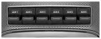
The auxiliary switch option package provides six switches mounted in the overhead console. These switches operate when the vehicle is running or from battery power, depending on the switchable fuse AUXF4's location in the upfitter relay box. We recommend, however, that the engine remain running to maintain battery charge when using the auxiliary switches for extended periods of time or higher current draws.
Note: When your vehicle has a diesel engine, use the auxiliary switches only when the engine is running. The glow plugs also drain battery power when the ignition key is in the on position. Using the auxiliary switches, even for limited amounts of time, can cause your battery to drain quickly and prevent your vehicle from restarting.
When switched on, the auxiliary switches provide electrical battery power for a variety of personal or commercial uses. Switches 1 through 4 provide 25 amps.
Switches 5 and 6 provide 40 amps.
The relay box for the auxiliary switches is in the rear of the engine compartment, near the back wall. See your authorized dealer for service.
The relays are coded as shown:
E220729
576
Each switch includes a blunt-cut, sealed wire. The wires are under the instrument
panel on the right-hand side of the passenger footwell.
E220730
The power leads are coded as shown:
|
Switch |
Circuit Number |
Wire Color |
Fuse Amp Rating |
|
AUX 1 |
CB117A |
Brown with green trace |
25A |
|
AUX 2 |
CB114A |
Violet with orange trace |
25A |
|
AUX 3 |
CB116A |
Blue with green trace |
25A |
577
|
Switch |
Circuit Number |
Wire Color |
Fuse Amp Rating |
|
AUX 4 |
CB113A |
Gray with brown trace |
25A |
|
AUX 5 |
CB115A |
Brown with blue trace |
40A |
|
AUX 6 |
CB118A |
Gray with orange trace |
40A |
The Upfitter Interface Module (UIM) is an electronic control module that operates equipment (such as lift buckets, cranes, motors, salt spreaders and snow plows) with external relays.
If you replace the module, it will require additional programming by the upfitter. Obtain this data directly from the upfitter company. The upfitter contact information is in the vehicle door opening.
For more information on the Upfitter Interface Module and the auxiliary switches, contact your upfitter.
578
Download Manual