Vehicle Checks
If doing some of your own service work, use the proper service manual. It tells you much more about how to service the vehicle than this manual can. To order the proper service manual, see Publication Ordering Information
0 459.
This vehicle has an airbag system. Before attempting to do your own service work, see Servicing the Airbag-Equipped Vehicle 0 88.
If equipped with remote vehicle start, open the hood before performing any service work to prevent remote starting the vehicle accidentally. See Remote Vehicle Start 0 38.
Keep a record with all parts receipts and list the mileage and the date of any service work performed. See Maintenance Records 0 445.
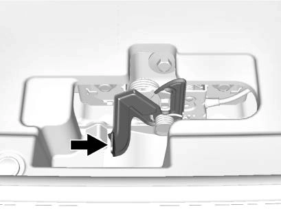
To open the hood:
Before closing the hood, be sure all the filler caps are on properly. Then bring the hood from full open to within 15 cm (6 in) from the closed position, pause, and push the front center of the hood with a swift, firm motion to fully close the hood.
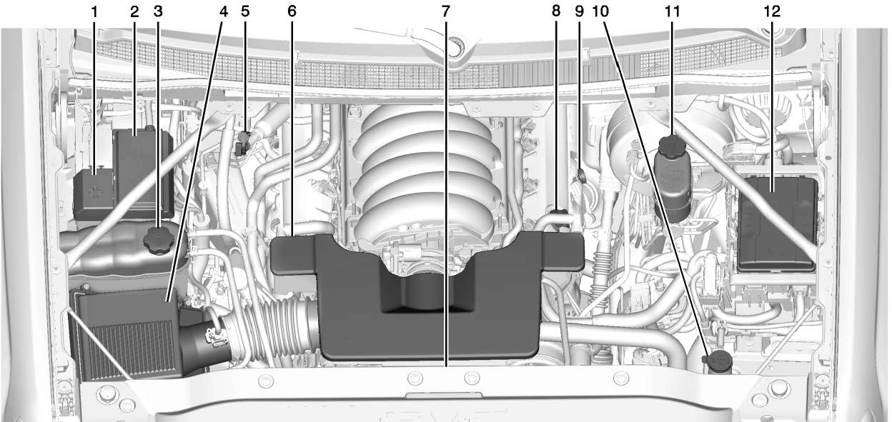
5.3L V8 Engine
0 347.
Brake Fluid 0 349.
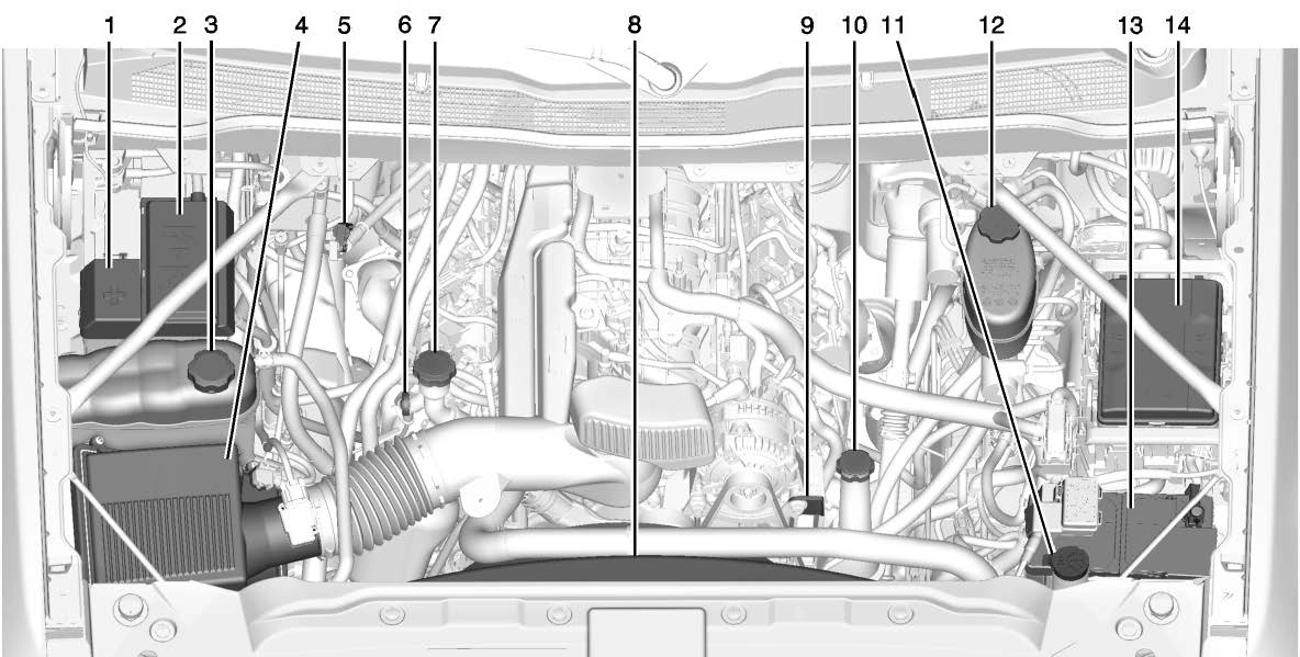
6.0L V8 Engine
See Power Steering Fluid (1500 Series) 0 346 or Power Steering Fluid (2500/3500 Series) 0 346.
0 347.
Brake Fluid 0 349.
0 350.
If the vehicle has a diesel engine and/or an Allison Transmission, see the Duramax diesel supplement.
For diesel engine vehicles, see “Engine Oil” in the Duramax diesel supplement.
To ensure proper engine performance and long life, careful attention must be paid to engine oil. Following these simple, but important steps will help protect your investment:
Check the engine oil level regularly, every 650 km (400 mi), especially prior to a long trip. The engine oil dipstick handle is a loop. See Engine Compartment Overview
0 329 for the location.
checking a cold engine prior to starting. Remove the dipstick and check the level.
. If unable to wait two hours, the engine must be off for at least 15 minutes if the engine is warm, or at least 30 minutes if the engine is not warm. Pull out the dipstick, wipe it with a clean paper towel or cloth, then push it back in all the way. Remove it again, keeping the tip down, and check the level.
the level. See “Selecting the Right Engine Oil” later in this section for an explanation of what kind of oil to use. For engine oil crankcase capacity, see Capacities and Specifications 0 447.
If a low oil Driver Information Center (DIC) message displays, check the oil level.
Follow these guidelines:
. To get an accurate reading, park the vehicle on level ground.
Check the engine oil level after the engine has been off for at least two hours. Checking the engine oil level on steep grades or too soon after engine shutoff can result in incorrect readings. Accuracy improves when
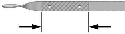
If the oil is below the cross-hatched area at the tip of the dipstick and the engine has been off for at least 15 minutes, add 1 L (1 qt) of the recommended oil and then recheck
See Engine Compartment Overview 0 329 for the location of the engine oil fill cap.
Add enough oil to put the level somewhere in the proper operating range. Push the dipstick all the way back in when through.
Selecting the right engine oil depends on both the proper oil specification and viscosity grade. See Recommended Fluids and Lubricants 0 441.
Specification
Use full synthetic engine oils that meet the dexos1 specification.
Engine oils that have been approved by GM as meeting the dexos1 specification are marked with the dexos1 approved logo.

Viscosity Grade
Use SAE 0W-20 viscosity grade engine oil
When selecting an oil of the appropriate viscosity grade, it is recommended to select an oil of the correct specification. See “Specification” earlier in this section.
Do not add anything to the oil. The recommended oils meeting the dexos1 specification are all that is needed for good performance and engine protection.
Engine oil system flushes are not recommended and could cause engine damage not covered by the vehicle warranty.
Used engine oil contains certain elements that can be unhealthy for your skin and could even cause cancer. Do not let used oil stay on your skin for very long. Clean your skin and nails with soap and water, or a good hand cleaner. Wash or properly dispose of clothing or rags containing used engine oil. See the manufacturer's warnings about the use and disposal of oil products.
Used oil can be a threat to the environment. If you change your own oil, be sure to drain all the oil from the filter before disposal. Never dispose of oil by putting it in the trash or pouring it on the ground, into sewers, or into streams or bodies of water. Recycle it by taking it to a place that collects used oil.
This vehicle has a computer system that indicates when to change the engine oil and filter. This is based on a combination of factors which
include engine revolutions, engine temperature, and miles driven.
Based on driving conditions, the mileage at which an oil change is indicated can vary considerably. For the oil life system to work properly, the system must be reset every time the oil is changed.
On some vehicles, when the system has calculated that oil life has been diminished, a CHANGE ENGINE OIL SOON message comes on to indicate that an oil change is necessary. Change the oil as soon as possible within the next 1 000 km (600 mi). It is possible that, if driving under the best conditions, the oil life system might indicate that an oil change is not necessary for up to a year. The engine oil and filter must be changed at least once a year and, at this time, the system must be reset. For vehicles without the CHANGE ENGINE OIL SOON
message, an oil change is needed when the OIL LIFE REMAINING percentage is near 0%. Your dealer has trained service people who will perform this work and reset the system. It is also important to check
the oil regularly over the course of an oil drain interval and keep it at the proper level.
If the system is ever reset accidentally, the oil must be changed at 5 000 km (3,000 mi) since the last oil change.
Remember to reset the oil life system whenever the oil is changed.
Reset the system whenever the engine oil is changed so that the system can calculate the next engine oil change. Always reset the engine oil life to 100% after every oil change. It will not reset itself. To reset the engine oil life system:
The oil life will change to 100%.
The oil life system can also be reset as follows:
See Driver Information Center (DIC) (Base Level) 0 154 or Driver Information Center (DIC) (Uplevel) 0 156.
If the vehicle has a CHANGE ENGINE OIL SOON message and it comes back on when the vehicle is started and/or the OIL LIFE REMAINING is near 0%, the engine oil life system has not been reset.
Repeat the procedure.
It is usually not necessary to check the transmission fluid level. The only reason for fluid loss is a transmission leak or overheated transmission. If a small leak is suspected, then use the following checking procedures to check the fluid level. However, if there is a large leak, then it may be necessary to have the vehicle towed to a dealer service department and have it repaired before driving the vehicle further.
Change the fluid and filter at the scheduled maintenance intervals listed in Maintenance Schedule 0 431. Be sure to use the transmission fluid listed in Recommended Fluids and Lubricants 0 441.
Before checking the fluid level, prepare the vehicle:
three seconds in each range. Then, move the shift lever back to P (Park).
one minute. Slowly release the brake pedal.
Information Center (DIC).
See Driver Information Center (DIC) (Base Level) 0 154 or Driver Information Center (DIC) (Uplevel) 0 156.
or operate the vehicle until the appropriate transmission fluid temperature is reached.
Cold Check Procedure
Use this procedure only as a reference to determine if the transmission has enough fluid to be operated safely until a hot check procedure can be made. The hot check procedure is the most accurate method to check the fluid level. Perform the hot check procedure at the first opportunity.
Use this cold check procedure to check fluid level when the
transmission temperature is between 27 °C and 32 °C (80 °F and 90 °F).

See Engine Compartment Overview 0 329.
three seconds, and then pull it back out again.

Hot Check Procedure
Use this procedure to check the transmission fluid level when the transmission fluid temperature is between 71 °C and 93 °C (160 °F and 200 °F).
The hot check is the most accurate method to check the fluid level. The hot check should be performed at the first opportunity in order to verify the cold check. The fluid level rises as fluid temperature increases, so it is important to ensure the transmission temperature is within range.
See Engine Compartment Overview 0 329.
three seconds, and then pull it back out again.
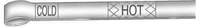
add only enough fluid to bring the level into the HOT band. It does not take much fluid,
generally less than 0.5 L (1 pt). Do not overfill.
Always check the fluid level at least twice using the procedure described previously. Consistency (repeatable readings) is important to maintaining proper fluid level. If readings are still inconsistent, contact the dealer.
It is usually not necessary to check the transmission fluid level. The only reason for fluid loss is a
transmission leak or overheated transmission. This vehicle is not equipped with a transmission fluid level dipstick. There is a special procedure for checking and changing the transmission fluid in these vehicles. Because this procedure is difficult, this should be done at the dealer. Contact the dealer for additional information or the procedure can be found in the service manual. See Publication Ordering Information 0 459.
Change the fluid and filter at the scheduled maintenance intervals listed in Maintenance Schedule 0 431. Be sure to use the
transmission fluid listed in Recommended Fluids and Lubricants 0 441.
If the vehicle has a diesel engine, see “8-Cylinder Pickup Models” under “Engine Air Cleaner/Filter” in the Duramax diesel supplement for the correct inspection and replacement procedures.
The engine air cleaner/filter is on the passenger side of the engine compartment. See Engine Compartment Overview 0 329.
For intervals on changing and inspecting the engine air filter, see Maintenance Schedule 0 431.
Do not start the engine or have the engine running with the engine air cleaner/filter housing open. Before removing the engine air cleaner/ filter, make sure that the engine air
cleaner/filter housing and nearby components are free of dirt and debris. Remove the engine air cleaner/filter. Lightly tap and shake the engine air cleaner/filter (away from the vehicle), to release loose dust and dirt. Inspect the engine air cleaner/filter for damage, and replace if damaged. Do not clean the engine air cleaner/filter or components with water or compressed air.
To inspect or replace the engine air cleaner/filter:
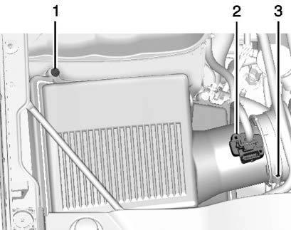
clamp (3).
If the vehicle has the Duramax diesel engine, see the Duramax diesel supplement.
The cooling system allows the engine to maintain the correct working temperature.
5.3L V8 Engine
6.0L V8 Engine
The cooling system in the vehicle is filled with DEX-COOL engine coolant. This coolant is designed to remain in the vehicle for 5 years or 240 000 km (150,000 mi), whichever occurs first.
The following explains the cooling system and how to check and add coolant when it is low. If there is a problem with engine overheating, see Engine Overheating 0 344.
Use a 50/50 mixture of clean, drinkable water and DEX-COOL coolant. This mixture:
Never dispose of engine coolant by putting it in the trash, or by pouring it on the ground, or into sewers, streams, or bodies of water. Have the coolant changed by an authorized service center, familiar with legal requirements regarding used coolant disposal. This will help protect the environment and your health.
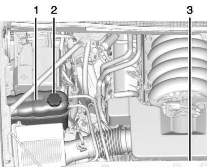
The coolant surge tank is located in the engine compartment on the passenger side of the vehicle. See Engine Compartment Overview
0 329.
The vehicle must be on a level surface when checking the coolant level.
5.3L V8 Shown, 6.0L V8 Similar
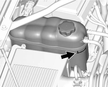
Check to see if coolant is visible in the coolant surge tank. If the coolant inside the coolant surge tank is boiling, wait until it cools down. The coolant level should be at or above
the full cold mark. If it is not, there may be a leak in the cooling system.
If coolant is visible but the coolant level is not at or above the full cold mark, see “How to Add Coolant to the Coolant Surge Tank for Gasoline Engines,” following.
If the vehicle has a diesel engine, see “Cooling System” in the Duramax diesel supplement for the proper coolant fill procedure.
If no coolant is visible in the surge tank, add coolant.
Turn the pressure cap slowly counterclockwise about one full turn. If a hiss is heard, wait for that to stop. A hiss means there is still some pressure left.
By this time, the coolant level
Light-Duty Coolant Surge Tank
Pressure Cap
Heavy-Duty Coolant Surge Tank
Pressure Cap
inside the coolant surge tank may be lower. If the level is lower, add more of the proper mixture to the coolant surge
tank until the level reaches the full cold mark.
If the vehicle has the Duramax diesel engine, see the Duramax diesel supplement.
The vehicle has several indicators to warn of engine overheating.
There is a coolant temperature gauge in the vehicle's instrument cluster. See Engine Coolant Temperature Gauge 0 141.
In addition, there are ENGINE OVERHEATED STOP ENGINE, ENGINE OVERHEATED IDLE ENGINE, and ENGINE POWER IS
REDUCED messages in the Driver Information Center (DIC).
If the decision is made not to lift the hood when this warning appears, get service help right away. See Roadside Assistance Program
0 454.
If the decision is made to lift the hood, make sure the vehicle is parked on a level surface.
Check to see if the engine cooling fans are running. If the engine is overheating, the fans should be running. If they are not, do not continue to run the engine. Have the vehicle serviced.
If No Steam is Coming from the Engine Compartment
The ENGINE OVERHEATED STOP ENGINE or the ENGINE OVERHEATED IDLE ENGINE
message, along with a low coolant condition, can indicate a serious problem.
If there is an engine overheat warning, but no steam is seen or heard, the problem may not be too serious. Sometimes the engine can get a little too hot when the vehicle:
0 298.
If the ENGINE OVERHEATED STOP ENGINE or the ENGINE OVERHEATED IDLE ENGINE
message appears with no sign of steam, try this for a minute or so:
N (Neutral) and let the engine idle.
If the temperature overheat gauge is no longer in the overheat zone or an overheat warning no longer displays, the vehicle can be driven. Continue to drive the vehicle slowly for about 10 minutes. Keep a safe vehicle distance from the vehicle in front. If the warning does not come back on, continue to drive normally and have the cooling system checked for proper fill and function.
If the warning continues, pull over, stop, and park the vehicle
right away.
If there is still no sign of steam and the vehicle is equipped with an engine driven cooling fan, push down the accelerator until the engine speed is about twice as fast as normal idle speed for at least five minutes while the vehicle is parked. If the warning is still there,
turn off the engine and get everyone out of the vehicle until it cools down.
If there is no sign of steam, idle the engine for five minutes while parked. If the warning is still displayed, turn off the engine until it cools down.
If an overheated engine condition exists and the ENGINE POWER IS REDUCED message displays, an overheat protection mode which alternates firing groups of cylinders helps to prevent engine damage. In this mode, a loss in power and engine performance will be noticed. This operating mode allows the vehicle to be driven to a safe place in an emergency. Driving extended distances and/or towing a trailer in the overheat protection mode should be avoided.
If the vehicle has a clutched engine cooling fan, when the clutch is engaged, the fan spins faster to provide more air to cool the engine. In most everyday driving conditions, the fan is spinning slower and the clutch is not fully engaged. This improves fuel economy and reduces fan noise. Under heavy vehicle loading, trailer towing, and/or high outside temperatures, the fan speed increases as the clutch more fully engages, so an increase in fan noise may be heard. This is normal and should not be mistaken as the transmission slipping or making extra shifts. It is merely the cooling system functioning properly. The fan
will slow down when additional cooling is not required and the clutch disengages.
This fan noise may also be heard when starting the engine. It will go away as the fan clutch partially disengages.
If the vehicle has electric cooling fan(s), the fans may be heard spinning at low speed during most everyday driving. The fans may turn off if no cooling is required. Under heavy vehicle loading, trailer towing, high outside temperatures,
or operation of the air conditioning system, the fans may change to high speed and an increase in fan noise may be heard. This is normal and indicates that the cooling system is functioning properly. The fans will change to low speed when additional cooling is no longer required.
The electric engine cooling fans may run after the engine has been turned. off. This is normal and no service is required.
The vehicle has electric power steering and does not use power steering fluid.
See Engine Compartment Overview
0 329 for reservoir location.
It is not necessary to regularly check power steering fluid unless there is a leak suspected in the system or an unusual noise is heard. A fluid loss in this system could indicate a problem. Have the system inspected and repaired.
Wait for the power steering system to cool, with the engine off, before checking the fluid.
To check the power steering fluid:
cool down.
The level should be between the ADD and FULL marks. If necessary, add only enough fluid to bring the level up to the hashed area between the ADD and FULL marks.
To determine what kind of fluid to use, see Recommended Fluids and Lubricants 0 441. Always use the proper fluid.
When windshield washer fluid needs to be added, be sure to read the manufacturer's instructions before use. Use a fluid that has sufficient protection against freezing in an area where the temperature may fall below freezing.
The vehicle has a low washer fluid message on the DIC that comes on when the washer fluid is low. The message is displayed for 15 seconds at the start of each ignition cycle. When the WASHER FLUID LOW ADD FLUID message displays, washer fluid will need to be added to the windshield washer fluid reservoir.
Open the cap with the washer symbol on it. Add washer fluid until the tank is full. See Engine Compartment Overview 0 329 for reservoir location.
Brakes
Disc brake pads have built-in wear indicators that make a high-pitched warning sound when the brake pads are worn and new pads are needed. The sound can come and go or be heard all the time the vehicle is moving, except when applying the brake pedal firmly.
Some driving conditions or climates can cause a brake squeal when the brakes are first applied or lightly applied. This does not mean something is wrong with the brakes.
Properly torqued wheel nuts are necessary to help prevent brake pulsation. When tires are rotated, inspect brake pads for wear and evenly tighten wheel nuts in the proper sequence to torque specifications in Capacities and Specifications 0 447.
Brake linings should always be replaced as complete axle sets.
See your dealer if the brake pedal does not return to normal height, or if there is a rapid increase in pedal travel. This could be a sign
that brake service may be required.
Always replace brake system parts with new, approved replacement parts. If this is not done, the brakes may not work properly. The braking performance expected can change in many other ways if the wrong replacement brake parts are installed or parts are improperly installed.
The brake master cylinder reservoir is filled with DOT 3 brake fluid. See Engine Compartment Overview
0 329 for the location of the reservoir.
There are only two reasons why the brake fluid level in the reservoir may go down:
Always clean the brake fluid reservoir cap and the area around the cap before removing it.
Do not top off the brake fluid. Adding fluid does not correct a leak. If fluid is added when the linings are worn, there will be too much fluid when new brake linings are installed. Add or remove fluid, as necessary, only when work is done on the brake hydraulic system.
When the brake fluid falls to a low level, the brake warning light comes on. See Brake System Warning Light 0 148.
Brake fluid absorbs water over time. Replace brake fluid at the specified intervals to prevent increased stopping distance. See Maintenance Schedule 0 431.
Check brake fluid by looking at the brake fluid reservoir. See Engine Compartment Overview 0 329.
The fluid level should be above MIN. If it is not, have the brake hydraulic system checked to see if there is a leak.
After work is done on the brake hydraulic system, make sure the level is above MIN but not over the MAX mark.
What to Add
Use only GM approved DOT 3 brake fluid from a clean, sealed container. See Recommended Fluids and Lubricants 0 441.
The original equipment battery is maintenance free. Do not remove the cap and do not add fluid.
Refer to the replacement number shown on the original battery label when a new battery is needed. See Engine Compartment Overview
0 329 for battery location.
See California Proposition
65 Warning 0 326 and the back cover.
Infrequent Usage: Remove the black, negative (−) cable from the battery to keep the battery from running down.
Extended Storage: Remove the black, negative (−) cable from the battery or use a battery trickle charger.
When to Check Lubricant
Refer to Maintenance Schedule
0 431 to determine when to check the lubricant.
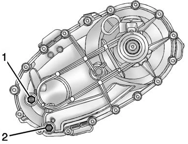
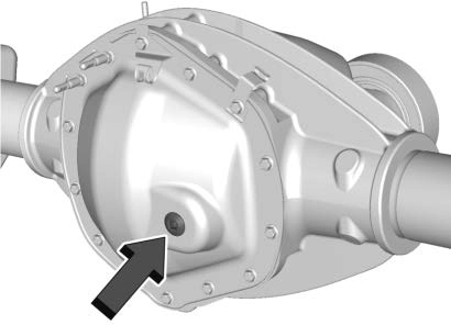
To get an accurate reading, the vehicle should be on a level surface.
If the level is below the bottom of the fill plug (1) hole, located on the transfer case, some lubricant will need to be added. Add enough lubricant to raise the level to the bottom of the fill plug (1) hole. Use care not to overtighten the plug.
When to Change Lubricant
Refer to Maintenance Schedule 0 431 to determine how often to change the lubricant.
What to Use
Refer to Recommended Fluids and Lubricants 0 441 to determine what kind of lubricant to use.
When to Check and Change Lubricant
It is not necessary to regularly check front axle fluid unless a leak is suspected, or an unusual noise is heard. A fluid loss could indicate a problem. Have it inspected and repaired.
How to Check Lubricant
To get an accurate reading, the vehicle should be on a level surface.
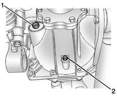
1500 Series
All Except 1500 Series
plug (1) hole.
plug (1) hole.
What to Use
Refer to Recommended Fluids and Lubricants 0 441 to determine what kind of lubricant to use.
It is not necessary to regularly check rear axle fluid unless a leak is suspected or an unusual noise is heard. A fluid loss could indicate a problem. Have it inspected and repaired.
All axle assemblies are filled by volume of fluid during production. They are not filled to reach a certain level. When checking the fluid level on any axle, variations in the readings can be caused by factory fill differences between the minimum and the maximum fluid volume.
Also, if a vehicle has just been driven before checking the fluid level, it may appear lower than normal because fluid has traveled out along the axle tubes and has not drained back to the sump area. Therefore, a reading taken
five minutes after the vehicle has been driven will appear to have a lower fluid level than a vehicle that has been stationary for an hour or two. The rear axle assembly must be supported on a flat, level surface to get a true reading.

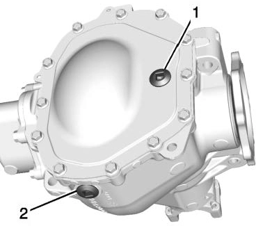
2500HD with 6.0L
All Other Series and Engines
To get an accurate reading, the vehicle should be on a level surface.
1.0 mm to 19.0 mm (0.04 in to
0.7 in) below the bottom of the fill hole, located on the rear axle. Add only enough fluid to reach the proper level.
hole, located on the rear axle. Add only enough fluid to reach the proper level.
Refer to Recommended Fluids and Lubricants 0 441 to determine what kind of lubricant to use.
General Motors warrants to the first person who purchases this vehicle for purposes other than resale and to each subsequent purchaser that this vehicle as manufactured by General Motors, was designed, built and equipped to conform at the time it left General Motors’s control with
all applicable U.S. EPA Noise Control Regulations. This warranty covers this vehicle as designed, built and equipped by General Motors, and is not limited to any particular part, component or system of the vehicle manufactured by General Motors. Defects in design, assembly or in any part, component or system of the vehicle as manufactured by General Motors, which, at the time it left General Motors’s control, caused noise emissions to exceed Federal standards, are covered by this warranty for the life of the vehicle.
The following information relates to compliance with federal noise emission standards for vehicles with a Gross Vehicle Weight Rating (GVWR) of more than 4 536 kg (10,000 lb). The Maintenance Schedule provides information on maintaining the noise control system to minimize degradation of the noise emission control system during the life of the vehicle. The noise control system warranty is given in the warranty manual.
These standards apply only to vehicles sold in the United States.
Federal law prohibits the following acts or the causing thereof:
or replacement, of any device or element of design incorporated into any new vehicle for the purpose of noise control prior to its sale or delivery to the ultimate purchaser or while it is in
use; or
Among those acts presumed to constitute tampering are the acts listed below.
Insulation:
Removal of the noise shields or any underhood insulation.
Engine:
Removal or rendering the engine speed governor, if equipped, inoperative so as to allow engine speed to exceed manufacturer specifications.
Fan and Drive:
if equipped, or rendering the clutch inoperative.
Air Intake:
Exhaust:
Do not use the accelerator pedal, and be ready to turn off the engine immediately if it starts.
normal effort. If the shift lever moves out of P (Park), contact your dealer for service.
While parked and with the parking brake set, try to turn the ignition off in each shift lever position.
Contact your dealer if service is required.
Park on a fairly steep hill, with the vehicle facing downhill. Keeping your foot on the regular brake, set the parking brake.
Contact your dealer if service is required.
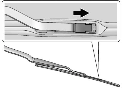
Windshield wiper blades should be replaced periodically. See Maintenance Schedule 0 431.
Replacement blades come in different types and are removed in different ways. For proper type and length, see Maintenance Replacement Parts 0 443.
To replace the wiper blade:
If the windshield needs to be replaced and the vehicle is equipped with a front camera sensor for the Driver Assistance Systems, a GM replacement windshield is recommended. The replacement windshield must be installed according to GM specifications for proper alignment. If it is not, these systems may not work properly, they may display messages, or they may not work at all. See your dealer for proper windshield replacement.
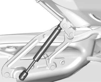
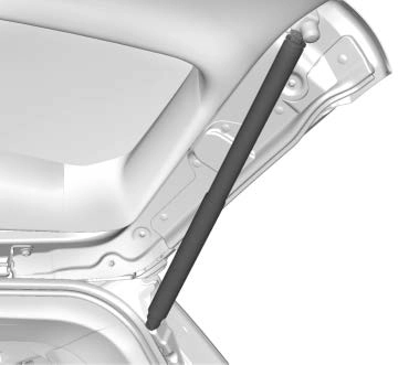
This vehicle is equipped with gas strut(s) to provide assistance in lifting and holding open the hood/ trunk/liftgate system in full open position.
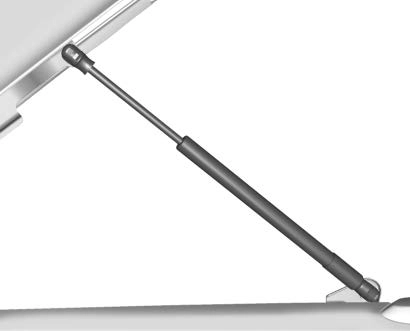
Hood
Trunk
See Maintenance Schedule 0 431.
Liftgate
Download Manual