Using the driving support systems
P. 243
P. 210
P. 251
*: If equipped
The pre-collision system does not record conversations, sounds or images of the inside of the vehicle.
Toyota may use the data recorded in this computer to diagnose malfunctions, conduct research and development, and improve quality.
Toyota will not disclose the recorded data to a third party except:
The image recording function can be disabled. However, if the func- tion is disabled, data from when the pre-collision system operates will not be available.
Two types of sensors, located behind the front grille and windshield, detect information necessary to operate the drive assist systems.
Radar sensor Camera sensor
WARNING
Observe the following precautions.
Otherwise, the radar sensor may not operate properly, possibly leading to an accident resulting in death or serious injury.
If the front of the radar sensor or the front or back of the front grille emblem is dirty or covered with water droplets, snow, etc., clean it.
Clean the radar sensor and front grille emblem with a soft cloth so you do not mark or damage them.
WARNING
If the radar sensor, front grille, or front bumper has been subjected to a strong impact, have the vehicle inspected by your Toyota dealer.
Observe the following precautions.
Otherwise, the camera sensor may not operate properly, possibly leading to an accident resulting in death or serious injury.
A: From the top of the windshield to approximately 0.4 in. (1 cm) below the bottom of the camera sensor
B: Approximately 7.9 in. (20 cm) (Approximately 4.0 in. [10 cm] to the right and left from the center of the camera sensor)
WARNING
If the wiper inserts or wiper blades need to be replaced, contact your Toyota dealer.
If the windshield needs to be replaced, contact your Toyota dealer.
When cleaning the inside of the windshield, do not allow glass cleaner to contact the lens. Also, do not touch the lens.
If the lens is dirty or damaged, contact your Toyota dealer.
*: If equipped
When the system determines that the possibility of a frontal colli- sion is high, the system applies greater braking force in relation to how strongly the brake pedal is depressed.
When the system determines that the possibility of a frontal colli- sion is high, the system warns the driver. If the system determines that the possibility of a frontal collision is extremely high, the brakes are automatically applied to help avoid the collision or reduce the collision speed.
WARNING
Do not use the pre-collision system instead of normal braking operations under any circumstances. This system will not prevent collisions or lessen collision damage or injury in every situation. Do not overly rely on this sys- tem. Failure to do so may lead to an accident, resulting in death or serious injury.
Read the following conditions carefully. Do not overly rely on this system and always drive carefully.
WARNING
In the following situations, disable the system, as it may not operate prop- erly, possibly leading to an accident resulting in death or serious injury:
The system is automatically enabled each time the engine switch is turned to the “ON” position.
Press “” or “” of meter control switches and select “PCS”, and press  .
.
Press “” or “” of meter control switches and select “PCS”, and press  to select the desired setting (on/off).
If the system is disabled, the PCS warning light will turn on and a message will be dis- played on the multi-information display.
The pre-collision warning timing can be changed on the multi-infor- mation display as following:
The operation timing setting is retained when the engine switch is turned off.
Press “” or “” of meter control switches and select “PCS”, and press  .
.
Press “” or “” of meter control switches and select “Sensitivity”, and press  to select the desired setting.
Far
The warning will begin to operate earlier than with the default timing.
This is the default setting.
The warning will begin to operate later than with the default timing.
The pre-collision system is enabled and the system determines that the pos- sibility of a frontal collision with a vehicle or pedestrian is high.
Each function is operational at the following speeds:
The system may not operate in the following situations:
The pre-collision system detects pedestri- ans based on the size, profile, and motion of a detected object. However, a pedes- trian may not be detected depending on the surrounding brightness and the motion, posture, and angle of the detected object, preventing the system from operating properly. (P. 241)
If either of the following occur while the pre-collision braking function is oper- ating, it will be canceled:
The pre-collision system may be temporarily unavailable or there may be a malfunction in the system.
(Defogging the windshield: P. 414, 421)
The LDA system recognizes visi- ble white (yellow) lines with the camera sensor on the upper por- tion of the windshield.
Functions included in LDA system
When the system determines that the vehicle might depart from its lane, a warning is dis- played on the multi-information display and the warning buzzer sounds to alert the driver.
When the warning buzzer sounds, check the surrounding road situation and carefully operate the steering wheel to move the vehicle back to the center of the lane.
*: If equipped
WARNING
Do not rely solely upon the LDA system. The LDA system does not auto- matically drive the vehicle or reduce the amount of attention that must be paid to the area in front of the vehicle. The driver must always assume full responsibility for driving safely by always paying careful attention to the sur- rounding conditions and operating the steering wheel to correct the path of the vehicle. Also, the driver must take adequate breaks when fatigued, such as from driving for a long period of time.
Failure to perform appropriate driving operations and pay careful attention may lead to an accident, resulting in death or serious injury.
When not using the LDA system, use the LDA switch to turn the system off.
Do not use the LDA system in the following situations.
The system may not operate properly and lead to an accident, resulting in death or serious injury.
LDA system on.
The LDA indicator illuminates and a message is displayed on the multi-information display.
Press the LDA switch again to turn the LDA system off.
When the LDA system is turned on or off, operation of the LDA system continues in the same condition the next time the engine is started.
The illumination condition of the indicator informs the driver of the system operation status.
Illuminated in green:
LDA system is operating.
Flashing in yellow:
Lane departure alert function is operating.
Displayed when the multi-informa- tion display is switched to the driv- ing assist system information screen.
Inside of displayed white lines is black
Indicates that the system is recog- nizing white (yellow) lines. When the vehicle departs from its lane, the white line displayed on the side the vehicle departs from flashes orange.
Indicates that the system is not able to recognize white (yellow) lines or is temporarily canceled.
This function operates when all of the following conditions are met.
This function operates when all of the following conditions are met.
 Warning” in screen of the multi-information display is set to on. (P. 101)
When the operation conditions are no longer met, a function may be tempo- rarily canceled. However, when the operation conditions are met again, oper- ation of the function is automatically restored. (P. 248)
The warning buzzer may be difficult to hear due to external noise, audio play- back, etc.
 When the system determines that the vehicle is swaying while the vehicle sway warning function is operating, a buzzer sounds and a warning message urging the driver to rest and the symbol shown in the illustration are simultaneously dis- played on the multi-information display.
Depending on the vehicle and road conditions, the warning may not operate.
The LDA system will not operate for the side on which white (yellow) lines could not be recognized.
In the following situations, the camera sensor may not detect white (yellow) lines and various functions may not operate normally.
Warning messages are used to indicate a system malfunction or to inform the driver of the need for caution while driving. (P. 555)
The following settings can be changed.
|
Function |
Setting details |
|
Lane departure alert function |
Adjust alert sensitivity |
|
Vehicle sway warning |
Turn function on and off |
|
Adjust alert sensitivity |
For how to change settings, refer to P. 623.
Use the dynamic radar cruise control with on freeways and highways.
Vehicle-to-vehicle distance switch
Display Indicators Set speed
Cruise control switch
*: If equipped
WARNING
Driving safely is the sole responsibility of the driver. Do not rely solely on the system, and drive safely by always paying careful attention to your sur- roundings.
The dynamic radar cruise control provides driving assistance to reduce the driver’s burden. However, there are limitations to the assistance provided.
Set the speed appropriately depending on the speed limit, traffic flow, road conditions, weather conditions, etc. The driver is responsible for checking the set speed.
Even when the system is functioning normally, the condition of the preced- ing vehicle as detected by the system may differ from the condition observed by the driver. Therefore, the driver must always remain alert, assess the danger of each situation and drive safely. Relying on this system or assuming the system ensures safety while driving can lead to an acci- dent, resulting in death or serious injury.
Observe the following precautions, as there are limitations to the assistance provided by the system.
Failure to do so may cause an accident resulting in death or serious injury.
The dynamic radar cruise control is only intended to help the driver in determining the following distance between the driver’s own vehicle and a designated vehicle traveling ahead. It is not a mechanism that allows care- less or inattentive driving, and it is not a system that can assist the driver in low-visibility conditions. It is still necessary for driver to pay close attention to the vehicle’s surroundings.
The dynamic radar cruise control determines whether the following dis- tance between the driver’s own vehicle and a designated vehicle traveling ahead is within a set range. It is not capable of making any other type of judgement. Therefore, it is absolutely necessary for the driver to remain vigilant and to determine whether or not there is a possibility of danger in any given situation.
The dynamic radar cruise control has limited capability to prevent or avoid a collision with a vehicle traveling ahead. Therefore, if there is ever any danger, the driver must take immediate and direct control of the vehicle and act appropriately in order to ensure the safety of all involved.
WARNING
Switch the dynamic radar cruise control off using the “ON-OFF” button when not in use.
Do not use dynamic radar cruise control in any of the following situations. Doing so may result in inappropriate speed control and could cause an acci- dent resulting in death or serious injury.
Vehicle speed may exceed the set speed when driving down a steep hill.
Note that vehicle-to-vehicle distance will close in when traveling on long downhill slopes.
|
|


The vehicle travels at the speed set by the driver. The desired vehicle-to- vehicle distance can also be set by operating the vehicle-to-vehicle dis- tance switch.
When a preceding vehicle driving slower than the set speed appears
When a vehicle is detected running ahead of you, the system automatically decelerates your vehicle. When a greater reduction in vehicle speed is necessary, the system applies the brakes (the stop lights will come on at this time). The system will respond to changes in the speed of the vehicle ahead in order to maintain the vehicle-to-vehicle distance set by the driver. Approach warning warns you when the system cannot decelerate suffi- ciently to prevent your vehicle from closing in on the vehicle ahead.
When there are no longer any preceding vehicles driving slower than the set speed
The system accelerates until the set speed is reached. The system then returns to constant speed cruising.
Radar cruise control indicator will come on and a message will be displayed on the multi-information display.
Press the button again to deacti- vate the cruise control.
If the “ON-OFF” button is pressed and held for 1.5 seconds or more, the system turns on in constant speed control mode. (P. 260)
Cruise control “SET” indicator will come on.
The vehicle speed at the moment the lever is released becomes the set speed.
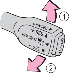 Increases the speed Decreases the speed
Fine adjustment: Momentarily move the lever in the desired direction.
Large adjustment: Hold the lever up or down to change the speed, and release when the desired speed is reached.
In the vehicle-to-vehicle distance control mode, the set speed will be increased or decreased as follows:
For the U.S. mainland, Hawaii
Fine adjustment: By 1 mph (1.6 km/h)*1 or 1 km/h (0.6 mph)*2 each time the lever is operated
Large adjustment: Increases or decreases in 1 mph (1.6 km/h)*1 or 1 km/h (0.6 mph)*2 increments for as long as the lever is held
Fine adjustment: By 1 mph (1.6 km/h)*1 or 1 km/h (0.6 mph)*2 each time the lever is operated
Large adjustment: Increases or decreases in 5 mph (8 km/h)*1 or 5 km/h (3.1 mph)*2 increments for as long as the lever is held
Fine adjustment: By 1 mph (1.6 km/h)*1 or 1 km/h (0.6 mph)*2 each time the lever is operated
Large adjustment: The speed will continue to change while the lever is held.
*1: When the set speed is shown in “MPH”
*2: When the set speed is shown in “km/h”
Long Medium Short
The vehicle-to-vehicle distance is set automatically to long mode when the engine switch is turned to the “ON” position.
If a vehicle is running ahead of you, the preceding vehicle mark will also be displayed.
|
Distance options |
Vehicle-to-vehicle distance |
|
Long |
Approximately 160 ft. (50 m) |
|
Medium |
Approximately 130 ft. (40 m) |
|
Short |
Approximately 100 ft. (30 m) |
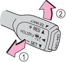 1 Pulling the lever toward you cancels the speed control.
The speed control is also canceled when the brake pedal is depressed.
However, cruise control does not resume when the vehicle speed is approximately 25 mph (40 km/h) or less.
a vehicle ahead, and sufficient automatic deceleration via the cruise control is not possible, the display will flash and the buzzer will sound to alert the driver. An example of this would be if another driver cuts in front of you while you are following a vehicle. Depress the brake pedal to ensure an appropriate vehicle-to- vehicle distance.
In the following instances, warnings may not occur even when the vehicle-to-vehicle distance is small.
When constant speed control mode is selected, your vehicle will main- tain a set speed without controlling the vehicle-to-vehicle distance. Select this mode only when vehicle-to-vehicle distance control mode does not function correctly due to a dirty radar sensor, etc.
With the cruise control off, press and hold the “ON-OFF” button for 1.5 seconds or more.
Immediately after the “ON-OFF” button is pressed, the radar cruise control indicator will come on. Afterwards, it switches to the cruise control indicator.
Switching to constant speed con- trol mode is only possible when operating the lever with the cruise control off.
Cruise control “SET” indicator will come on.
The vehicle speed at the moment the lever is released becomes the set speed.
Adjusting the speed setting: P. 257
Canceling and resuming the speed setting: P. 259
The vehicle can accelerate by operating the accelerator pedal. After acceler- ating, the set speed resumes. However, during vehicle-to-vehicle distance control mode, the vehicle speed may decrease below the set speed in order to maintain the distance to the preceding vehicle.
If vehicle-to-vehicle distance control mode is automatically canceled for any other reason, there may be a malfunction in the system. Contact your Toyota dealer.
Constant speed control mode is automatically canceled in the following situa- tions:
If constant speed control mode is automatically canceled for any other rea- son, there may be a malfunction in the system. Contact your Toyota dealer.
If the brakes are applied automatically while the vehicle is in vehicle-to-vehi- cle distance control mode, a brake system operation sound may be heard. This does not indicate a malfunction.
In the case of the following and depending on the conditions, operate the brake pedal when deceleration of the system is insufficient or operate the accelerator pedal when acceleration is required.
As the sensor may not be able to correctly detect these types of vehicles, the approach warning (P. 259) may not be activated.
In the case of the following conditions, operate the brake pedal (or accelera- tor pedal, depending on the situation) as necessary.
As the sensor may not be able to correctly detect vehicles ahead, the system may not operate properly.
Indicators
Cruise control switch
1 Press the “ON-OFF” button to activate the cruise control.
Cruise control indicator will come on.
Press the button again to deacti- vate the cruise control.
“SET” indicator will come on.
The vehicle speed at the moment the lever is released becomes the set speed.
*: If equipped
Increases the speed Decreases the speed
Fine adjustment: Momentarily move the lever in the desired direc- tion.
Large adjustment: Hold the lever in the desired direction.
The set speed will be increased or decreased as follows:
Fine adjustment: By approximately 1 mph (1.6 km/h) each time the lever is operated.
Large adjustment: The set speed can be increased or decreased continu- ally until the lever is released.
The speed setting is also canceled when the brakes are applied.
Resuming is available when the vehicle speed is more than approx- imately 25 mph (40 km/h).
Cruise control will stop maintaining the vehicle speed in any of the following situations.
At this time, the memorized set speed is not retained.
Press the “ON-OFF” button once to deactivate the system, and then press the button again to reactivate the system.
If the cruise control speed cannot be set or if the cruise control cancels imme- diately after being activated, there may be a malfunction in the cruise control system. Have the vehicle inspected by your Toyota dealer.
|
|
Turns the intuitive parking assist on/off
When on, the indicator light comes on to inform the driver that the system is operational.
*: If equipped
Front corner sensor opera- tion
Rear corner sensor operation Rear center sensor operation
The system operates when the vehicle approaches an obstacle, as shown by the following table.
When 2 or more obstacles are detected simultaneously, the buzzer sys- tem responds to the nearest zone.
|
Approximate distance to obstacle |
Display and buzzer |
|
2.0 ft. (60 cm) to 1.5 ft. (45 cm) |
Intermittent |
|
1.5 ft. (45 cm) to 1.0 ft. (30 cm) |
Fast intermittent |
|
Less than 1.0 ft. (30 cm) |
Continuously |
Rear corner sensors
|
Approximate distance to obstacle |
Display and buzzer |
|
2.8 ft. (85 cm) to 2.0 ft. (60 cm) |
Intermittent |
|
2.0 ft. (60 cm) to 1.3 ft. (40 cm) |
Fast intermittent |
|
Less than 1.3 ft. (40 cm) |
Continuously |
Rear center sensor
|
Approximate distance to obstacle |
Display and buzzer |
|
5.9 ft. (180 cm) to 3.3 ft. (100 cm) |
Intermittent |
|
3.3 ft. (100 cm) to 2.5 ft. (75 cm) |
Fast intermittent |
|
2.5 ft. (75 cm) to 1.6 ft. (50 cm) |
Very fast intermittent |
|
Less than 1.6 ft. (50 cm) |
Continuously |
The buzzer will change in the following manner.
 Detection range of the sensors Approximately 5.9 ft. (180 cm) Approximately 2.0 ft. (60 cm) Approximately 2.8 ft. (85 cm)
The diagram shows the detection range of the sensors. Note that the sensors may not be able to detect obstacles that are extremely close to the vehicle.
 The range of the sensors may change depending on the shape of the object, etc.
P. 557, 558
This ISM device complies with Canadian ICES-001.
WARNING
Pay particular attention to the following instances in where this may occur. Failing to do so way result in the vehicle being unable to be driven or parked safety and possibly cause an accident.
WARNING
NOTICE
In the following situations, the system may not function correctly due to a sensor malfunction, etc. Have the vehicle checked by your Toyota dealer.
If the error occurs even if there is no ice, snow or mud on the sensor, it is likely that the sensor is malfunctioning.
Do not apply intensive bursts of water or steam to the sensor area. Doing so may result in the sensor malfunctioning.
Refer to the “NAVIGATION AND MULTIMEDIA SYSTEM OWNER’S MANUAL”.
Vehicles with Entune Audio (Multimedia system types: P. 322)
The rear view image is displayed when the shift lever is in R and the engine switch is in the “ON” posi- tion.
The rear view monitor system will be deactivated when the shift lever is in any position other than R.
|
|

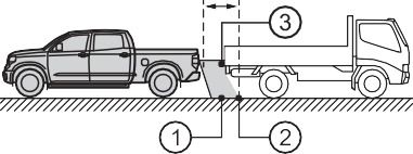
Vehicle width guide lines
Displays a guide path when the vehicle is being backed straight up. The displayed width is wider than the actual vehicle width.
This lines indicate the estimated vehicle center on the ground.
Displays a point approximately 1.5 ft. (0.5 m) (red) from the edge of the bumper.
Displays a point approximately 3 ft. (1 m) (blue) from the edge of the bumper.
The image adjustment proce- dure for the rear view monitor system screen is the same as the procedure for adjusting the screen. (P. 333)
If dirt or foreign matter (such as water droplets, snow, mud, etc.) is adhering to the camera, it cannot transmit a clear image. In this case, flush it with a large quantity of water and wipe the camera lens clean with a soft and wet cloth.
The distance guide lines and the vehicle width guide lines may not actually be parallel with the dividing lines of the parking space, even when they appear to be so. Be sure to check visually.
The distances between the vehicle width guide lines and the left and right dividing lines of the parking space may not be equal, even when they appear to be so. Be sure to check visually.
The distance guide lines give a distance guide for flat road sur- faces. In any of the following situations, there is a margin of error between the fixed guide lines on the screen and the actual dis- tance/course on the road.
 The distance guide lines will appear to be closer to the vehi- cle than the actual distance. Because of this, objects will appear to be farther away than they actually are. In the same way, there will be a margin of error between the guide lines and the actual distance/course on the road.
 The distance guide lines will appear to be further from the vehicle than the actual dis- tance. Because of this, objects will appear to be closer than they actually are. In the same way, there will be a margin of error between the guide lines and the actual distance/course on the road.
 When any part of the vehicle sags due to the number of pas- sengers or the distribution of the load, there is a margin of error between the fixed guide lines on the screen and the actual distance/course on the road.
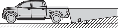
The distance guide lines are displayed according to flat surfaced objects (such as the road). It is not possible to determine the posi- tion of three-dimensional objects (such as vehicles) using the vehi- cle width guide lines and distance guide lines. When approaching a three-dimensional object that extends outward (such as the flatbed of a truck), be careful of the following.
 Visually check the surroundings and the area behind the vehi- cle. In the case shown below, the truck appears to be outside of the vehicle width guide lines and the vehicle does not look as if it hits the truck. However, the rear body of the truck may actually cross over the vehicle width guide lines. In reality if you back up as guided by the vehicle width guide lines, the vehicle may hit the truck.
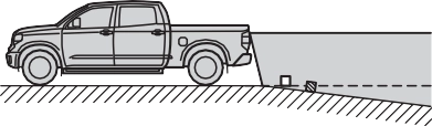
 Visually check the surroundings and the area behind the vehi- cle. On the screen, it appears that a truck is parking at point
. However, in reality if you back up to point , you will hit the truck. On the screen, it appears that is closest and is farthest away. However,
in reality, the distance to 1
and is the same, and 2 is farther than and .
If you notice any of the following symptoms, refer to the likely cause and the solution, and re-check.
If the symptom is not resolved by the solution, have the vehicle inspected by your Toyota dealer.
|
Likely cause |
Solution |
|
The image is difficult to see
|
|
|
The vehicle is in a dark area
The temperature around the lens is either high or low
The outside temperature is low
There are water droplets on the camera
It is raining or humid
Foreign matter (mud, etc.) is adhering to the camera
There are scratches on the cam- era
Sunlight or headlights are shining directly into the camera
The vehicle is under fluorescent lights, sodium lights, mercury lights, etc.
|
If this happens due to these causes, it does not indicate a malfunction. Back up while visually checking the vehicle’s surroundings. (Use the monitor again once conditions have been improved.) The procedure for adjusting the pic- ture quality of the rear view monitor system is the same as the proce- dure for adjusting the screen. |
|
The image is blurry
|
|
|
Dirt or foreign matter (such as water droplets, snow, mud, etc.) is adher- ing to the camera. |
Flush the camera with a large quan- tity of water and wipe the camera lens clean with a soft and wet cloth. |
|
The image is out of alignment
|
|
|
The camera or surrounding area has received a strong impact. |
Have the vehicle inspected by your Toyota dealer. |
|
The fixed guide lines are very far out of alignment
|
|
|
The camera position is out of align- ment. |
Have the vehicle inspected by your Toyota dealer. |
|
The vehicle is tilted (there is a heavy load on the vehicle, tire pressure is low due to a tire punc- ture, etc.)
The vehicle is used on an incline.
|
If this happens due to these causes, it does not indicate a malfunction. Back up while visually checking the vehicle’s surroundings. |
WARNING
The rear view monitor system is a supplemental device intended to assist the driver when backing up. When backing up, be sure to visually check all around the vehicle both directly and using the mirrors before proceeding.
Observe the following precautions to avoid an accident that could result in death or serious injuries.
Use caution, just as you would when backing up any vehicle.
When and how much to turn the steering wheel will vary according to traf- fic conditions, road surface conditions, vehicle condition, etc. when park- ing. It is necessary to be fully aware of this before using the rear view monitor system.
NOTICE
Assists the driver in making the decision when changing lanes
These functions use same sensors.
|
|
Multi-information display
Turning the BSM function/RCTA function on/off. (P. 286)
Blind Spot Monitor function:
When a vehicle is detected in a blind spot of the outside rear view mir- rors or approaching rapidly from behind into a blind spot, the outside rear view mirror indicator on the detected side will illuminate. If the turn signal lever is operated toward the detected side, the outside rear view mirror indicator will flash.
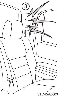
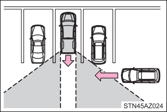
Rear Cross Traffic Alert function:
When a vehicle approaching from the right or left at the rear of the vehi- cle is detected, both outside rear view mirror indicators will flash.
*: If equipped
When a vehicle approaching from the right or left rear of the vehicle is detected, a buzzer sounds from behind the left-hand rear pillar.
When the BSM function is turned on, the indicator illuminates.
When the RCTA function is turned on, the indicator illuminates.
Press “<” or “>” of meter control switches and select .
Press “” or “” of meter control switches and select “BSM” or “RCTA”, and press  to select the desired setting (on/off).
The BSM (Blind Spot Monitor) outside rear view mirror indicators brightness can be changed on the multi-information display as follow- ing:
Press “<” or “>” of meter control switches and select .
Press “” or “” of meter control switches and select “Vehicle Settings”, and then press  .
.
Press “” or “” of meter control switches and select “BSM
Brightness”, and then press  to select the desired setting (bright/dim).
Press “<” or “>” of meter control switches and select .
Press “” or “” of meter control switches and select “Vehicle Settings”, and then press  .
.
Press “” or “” of meter control switches and select “RCTA Vol- ume”, and then press  to select the desired setting.
The buzzer volume changes with each  press.
When under strong sunlight, the outside rear view mirror indicator may be dif- ficult to see.
Rear Cross Traffic Alert function may be difficult to hear over noises such as high audio volume.
If a system malfunction is detected due to any of the following reasons, warn- ing messages will be displayed: (P. 557, 558)
For vehicles sold in the U.S.A. FCC ID: OAYSRR3A
This device complies with part 15 of the FCC Rules. Operation is subject to the following three conditions:
FCC Warning
Changes or modifications not expressly approved by the party responsible for compliance could void the user’s authority to operate the equipment.
For vehicles sold in Canada Applicable law: Canada 310
This device complies with Industry Canada licence-exempt RSS standard(s). Operation is subject to the following two conditions: (1) this device may not cause interference, and (2) this device must accept any interference, includ- ing interference that may cause undesired operation of the device.
Frequency bands: 24.05 – 24.25 GHz Output power: less than 20 milliwatts
WARNING
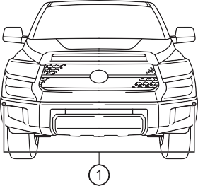
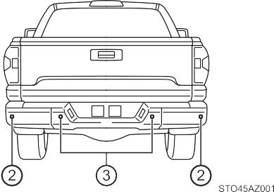
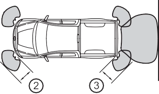
One Blind Spot Monitor sensor installed inside the left and right side of the vehicle rear bumper respectively. Observe the following to ensure the Blind Spot Monitor system can function correctly.
The areas that vehicles can be detected in are outlined below.
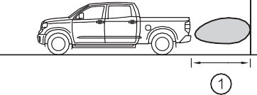
The range of the detection area extends to:
Approximately 11.5 ft. (3.5 m) from the side of the vehicle
The first 1.6 ft. (0.5 m) from the side of the vehicle is not in the detection area
Approximately 3.3 ft. (1 m) for- ward of the rear bumper
The Blind Spot Monitor function is not designed to detect the following types of vehicles and/or objects:
*: Depending on conditions, detection of a vehicle and/or object may occur
|
|

Approaching vehicles Detection areas
The areas that vehicles can be detected in are outlined below.
To give the driver a more consistent time to react, the buzzer can alert for faster vehicles from farther away.
Example:
|
Approaching vehicle |
Speed |
1 Approximate alert distance |
|
Fast |
18 mph (28 km/h) |
65 ft. (20 m) |
|
Slow |
5 mph (8 km/h) |
18 ft. (5.5 m) |
The Rear Cross Traffic Alert function is not designed to detect the following types of vehicles and/or objects.
*: Depending on conditions, detection of a vehicle and/or object may occur.
The Rear Cross Traffic Alert function may not detect vehicles correctly in the following conditions.
 Vehicles that the sensors cannot detect because of obstacles
“2WD” (high speed position, two-wheel drive)
Use this for normal driving on dry hard-surfaced roads. This position gives greater economy, quietest ride and least wear.
Use this for driving only on tracks that permit the tires slide, like off-road, icy or snow-covered roads. This position provides greater traction than two-wheel drive.
The “4HI” indicator will come on.
Use this for maximum power and traction. Use “4L” for climbing or descending steep hills, off-road driving, and hard pulling in sand, mud or deep snow.
The “4LO” indicator will come on.
*: If equipped
The “4HI” indicator will come on.
The “4HI” indicator will go off.
Shift the shift lever to N.
Push and turn the front-wheel drive control switch to “4L”.
The “4LO” indicator will come on.
Shift the shift lever to N.
Push and turn the front-wheel drive control switch to “4H”.
The “4LO” indicator will go off.
VSC is automatically turned off.
The transfer mode may not successfully change. Drive straight ahead while accelerating or decelerating, or drive in reverse.
The transfer mode may not successfully change. Operate the front-wheel drive control switch again.
The shift lever is not in N and/or the vehicle is moving. Stop the vehicle com- pletely, shift the shift lever to N and make sure that the indicator stops flash- ing.
There may be a malfunction in the four-wheel drive system. Have the vehicle inspected by your Toyota dealer immediately.
You should drive in four-wheel drive for at least 10 miles (16 km) each month. This will assure that the front drive components are lubricated.
Press the  briefly to turn on the system.
The “AUTO LSD” indicator will come on.
To turn off the system, press  again.
Stop the vehicle completely, and
press  for more than 3 sec- onds.
The “AUTO LSD” and VSC off indicators will come on.
To turn off the system, press  again.
The system will cease operation and a buzzer will alert the driver. At this time, the “TRAC OFF” indicator will come on. Stop the vehicle in a safe place. (There is no problem with continuing normal driving.) The system will be auto- matically restored after a short time.
Generates an increased level of braking force after the brake pedal is depressed when the system detects a panic stop situation
Helps the driver to control skidding when swerving suddenly or turning on slippery road surfaces
Helps the driver to control trailer sway by selectively applying brake pressure for individual wheels and reducing driving torque when trailer sway is detected
Helps to maintain drive power and prevent the drive wheels from spinning when starting the vehicle or accelerating on slippery roads
Helps to reduce the backward movement of the vehicle when start- ing on an uphill
The slip indicator light will flash
while the TRAC/VSC/Trailer Sway Control systems are operating.
If the vehicle gets stuck in mud, dirt or snow, the TRAC system may
reduce power from the engine to the wheels. Pressing  to turn the system off may make it easier for you to rock the vehicle in order to free it.
2WD models and 2WD mode on 4WD models To turn the TRAC system off,
press  .
.
The “AUTO LSD” indicator light will come on.
Press  again to turn the system back on.
4H mode on 4WD models
To turn the TRAC system off,
press  .
.
The “TRAC OFF” indicator light will come on.
Press  again to turn the system back on.
4L mode on 4WD models
To turn the TRAC system off,
press and hold  for more than 3 seconds while the vehi- cle is stopped.
The VSC off and “TRAC OFF” indicator light will come on.
Press  again to turn the system back on.
2WD models and 2WD mode on 4WD models
To turn the TRAC, VSC and Trailer Sway Control systems off, stop the vehi-
cle completely, and then press and hold  for more than 3 seconds while the AUTO LSD system is activated. (P. 298)
4H mode on 4WD models
To turn the TRAC, VSC and Trailer Sway Control systems off, press and
hold  for more than 3 seconds while the vehicle is stopped. The VSC off and “TRAC OFF” indicator light will come on.
Press  again to turn the system back on.
On vehicles with pre-collision system, pre-collision brake assist and pre-colli- sion braking will also be disabled. The PCS warning light will come on and the message will be shown on the multi-information display. (P. 563)
TRAC cannot be operated. Contact your Toyota dealer.
When the following four conditions are met, the hill-start assist control will operate:
The hill-start assist control will turn off in any of the following situations: The shift lever is shifted to P or N
If both the TRAC and VSC systems are turned off, automatic re-enabling will not occur when vehicle speed increases.
TRAC will cease operation, and the slip indicator will change from flashing to being on continuously to alert the driver. Stop the vehicle in a safe place. (There is no problem with continuing normal driving.)
VSC and Trailer Sway Control are automatically turned off.
WARNING
The ABS is not designed to shorten the vehicle’s stopping distance. Always maintain a safe distance from the vehicle in front of you, especially in the following situations:
Directional control and power may not be achievable while driving on slip- pery road surfaces, even if the TRAC/VSC system is operating.
Drive the vehicle carefully in conditions where stability and power may be lost.
WARNING
The slip indicator light flashes. Always drive carefully. Reckless driving may cause an accident. Exercise particular care when the indicator light flashes.
Be especially careful and drive at a speed appropriate to the road condi- tions. As these are the systems to help ensure vehicle stability and driving force, do not turn the TRAC/VSC/Trailer Sway Control systems off unless necessary.
Trailer Sway Control is part of the VSC system and will not operate if VSC is turned off or experiences a malfunction.
Make sure that all tires are of the specified size, brand, tread pattern and total load capacity. In addition, make sure that the tires are inflated to the recommended tire inflation pressure level.
The ABS, TRAC, VSC and Trailer Sway Control systems will not function correctly if different tires are installed on the vehicle.
Contact your Toyota dealer for further information when replacing tires or wheels.
Using tires with any kind of problem or modifying the suspension will affect the driving assist systems, and may cause a system to malfunction.
The Trailer Sway Control system is not able to reduce trailer sway in all situ- ations. Depending on many factors such as the conditions of the vehicle, trailer, road surface, and driving environment, the Trailer Sway Control sys- tem may not be effective. Refer to your trailer owner’s manual for informa- tion on how to tow your trailer properly.
Observe the following precautions.
Failure to do so may cause death or serious injury.
Do not try to control trailer swaying by turning the steering wheel.
Do not increase speed. Do not apply vehicle brakes.
If you make no extreme correction with the steering or brakes, your vehicle and trailer should stabilize. (P. 190)
Trailer connection indicator
When the trailer has been connected, the indicator comes on green.
GAIN (+/-) selection button
Pressing the GAIN (+/-) buttons will adjust the amount of power that can be outputted to the trailer brakes. The gain can be adjusted from 0 (no trailer braking) to 10 (maximum output) in 0.5 increments. Each press of the button will increase or decrease the gain setting by one step. The gain value will appear in the multi-information display.
*: If equipped
Trailer brake type can be selected by using the multi-information. The combination meter will show which trailer brake type is selected in the multi-information display.
Adjusting this slider position will engage the trailer’s brakes only. If the manual TRAILER BRAKE OUTPUT slider is used while the vehicle brake is applied, the greater of the two outputs will be sent to the trailer brakes.
Press “<” or “>” of meter control switches and select .
Press “” or “” of meter control switches and select “Vehicle Set- tings”, and press  .
.
Press “” or “” of meter control switches and select “TBC Trailer Type”, and press  to select the correct type of trailer brakes that are equipped on the trailer.
Changing trailer brake type will cause the current gain setting to reset to zero. Make sure to set the gain as described in the following sec- tion.
Gain setting on trailer brake controller should be set for a specific tow- ing condition. Gain setting should be adjusted each time the vehicle load, trailer load, road conditions, or weather changes. Setting the gain value to 0 will disable the trailer brake controller output.
Make sure the trailer brakes are in good working condition and functioning normally. See trailer dealer if necessary.
Hook up the trailer and make proper electrical connections.
Select the correct type of trailer brakes that are equipped on the trailer by using the multi-information display.
Drive vehicle with trailer attached on a level road surface similar to towing condition and in traffic-free environment. Driving speed should be approximately 20 - 25 mph [35 - 40 km/h].
Using the GAIN (+/-) selection buttons, set a starting gain of 5.0.
While driving 20 - 25 mph [35 - 40 km/h], fully apply the manual TRAILER BRAKE OUTPUT slider.
For confirmation, repeat steps and until desired gain setting is reached (just below point of trailer wheel lock-up).
Please turn off the intuitive parking assist while towing a trailer. If left on, sonar sensors will detect the trailer being towed.
Wheel lock-up occurs when the trailer wheel squeals or tire smoke occurs. Trailer wheels may not lock-up while driving heavily loaded trailer. During this case, adjust the Trailer gain to the highest allowable setting for the towing condition.
The gain setting data will be reset.
WARNING
It is the responsibility of the driver to make sure the trailer brakes are func- tioning normally and adjusted appropriately. Failure to check and maintain trailer brakes may result in loss of vehicle control, crash, or serious injury. Trailer brake control system will work with most electric and electric-over- hydraulic trailer braking systems up to 3 axles (24A output to trailer brakes). Please be sure to test compatibility with the system at low speeds and in a safe area. If a warning message appears in the multi-information display (P. 563), have the vehicle inspected by your Toyota dealer immediately. Some electric-over-hydraulic trailer brakes will take some minimum output to activate. Trailer brake control system will not work with trailer hydraulic surge brakes.
When stopping with ABS activated, output to the trailer might be reduced in order to reduce the likelihood of trailer wheels to lock. The trailer is not equipped with ABS. Drive safely on slippery road surfaces.
Download Manual